
Originally Posted by
Don42

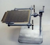
The little board grippers swivel, so if the arms spring a little when tightened the grippers will still stay parallel to the board edges and hold it securely. The grippers have V-grooves in them to engage different board thicknesses. The swivel pins fit the holes within about .0005" so there is no perceptible vertical play in the grippers or the board held in them. The arms can be set anywhere on the crossbar to accomodate different board sizes. There's a flat milled on the back of the crossbar so when the thumbscrews are tightened the arms will be parallel to each other. The thumbscrews are machined from brass so as not to mar or chew up the crossbar when tightened securely. They're 1/4-28 thread. They're so danged purty I couldn't resist polishing them up and spraying them with a clear protective coating. Could have nickel-plated them, but I liked the appearance of the brass against the other metals. The base is a chunk of 6-1/4 x 6-1/4 x 1/2" steel scrap I found shaped as shown at the steelmonger. They're "drops" from plasma cutouts. Very small windows in a submarine? Who knows! I welded the "starting hole" shut, cleaned up the edges on a belt sander, and skinned the top surface with a flycutter in the mill to remove the millscale and give a nice-looking and platable surface. It weighs about 6 lb, making a very stable vise. The board-holding assembly "nods" up and down for a convenient working angle. That nodding angle is preserved when the board is rotated about a front-to-back axis to work on the other side. The "nodding" axel is tightened in place with a "cotter" (term courtesy of Guy Lautard) like the quill lock on a Bridgeport. The little lever tightens a screw which snugs up two .500" dia brass slugs inside a hole, each slug having a crosswise cylindrical cutout. The hole in the cotter body containing the slugs is perpendicular to the nodding axel hole and partially intersects it. When the screw is tightened with the little lever, the cylindrical cutouts in the slugs pinch together and grip the 3/8" dia nodding axel very securly. The lever moves less than 90 degrees from completely free to locked up tight. I didn't use a cotter on the board-flipping axel because I wanted positive stops in two positions 180 deg apart. Cctvise3.jpg shows how I crossdrilled the threaded part that goes inside the knurled locking nut and then milled away a shelf leaving about a .020" detent where the holes were. The end of the axel fits inside the axial .376" dia hole in this part. A short pin projecting radially from the axel then engages these detents, and the knurled locking knob secures it in place. The threads, 5/8" x 20, were lathe-cut on both the male part and inside the knurled collar. The collar took three tries to get it right. Happy to say that the knurl, the last operation on the collar, turned out perfect. I made a little case-hardened washer to go between the pin and the back of the collar, and the pin is a hardened dowel pin. Locking action is crisp. Loosen knurled collar half a turn, flip board 180, tighten collar and resume solderslinging. The cotter body, locking lever, nodding axel, and knurled collar that get touched with fingers a lot are nickel-plated to resist the acids in fingerprints. The rest of the parts, including the base (but not the brass screws of course) are zinc-plated for appearance and rust prevention. Zinc is quicker, and my nickle plating vessel is just a 1-liter pyrex beaker so it's pretty much limited to small parts.

 LinkBack URL
 About LinkBacks


 Reply With Quote


Bookmarks