
 LinkBack URL
 About LinkBacks


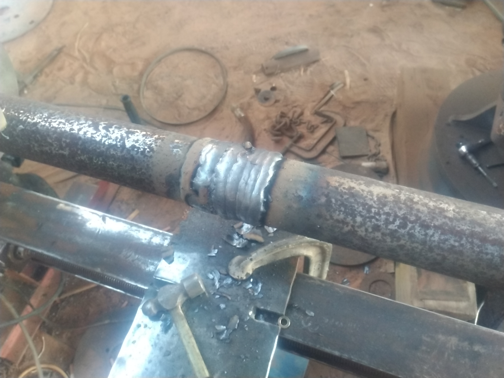
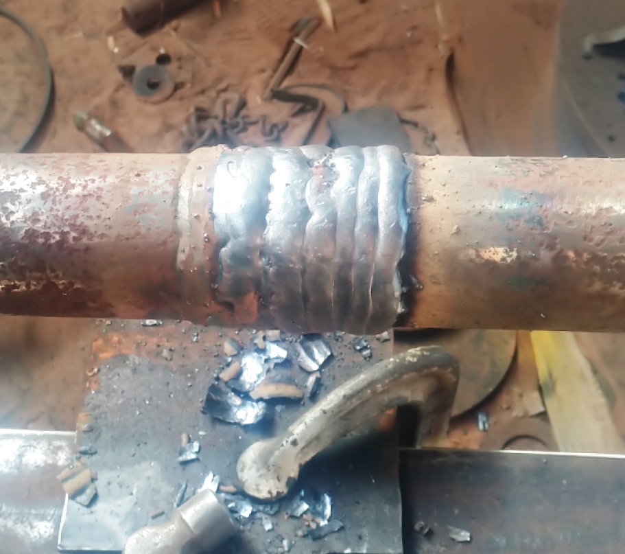
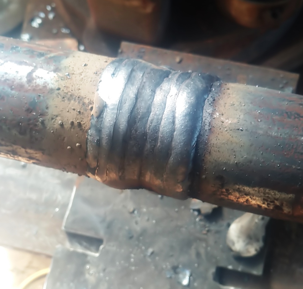
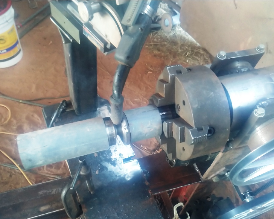
I wasn't going to post this until I am finished with the build, but I have been using this thing for the past 6 months or longer as it is. There will probably always be some tweaks I will be doing to it. It just functions too well not to go ahead and share.
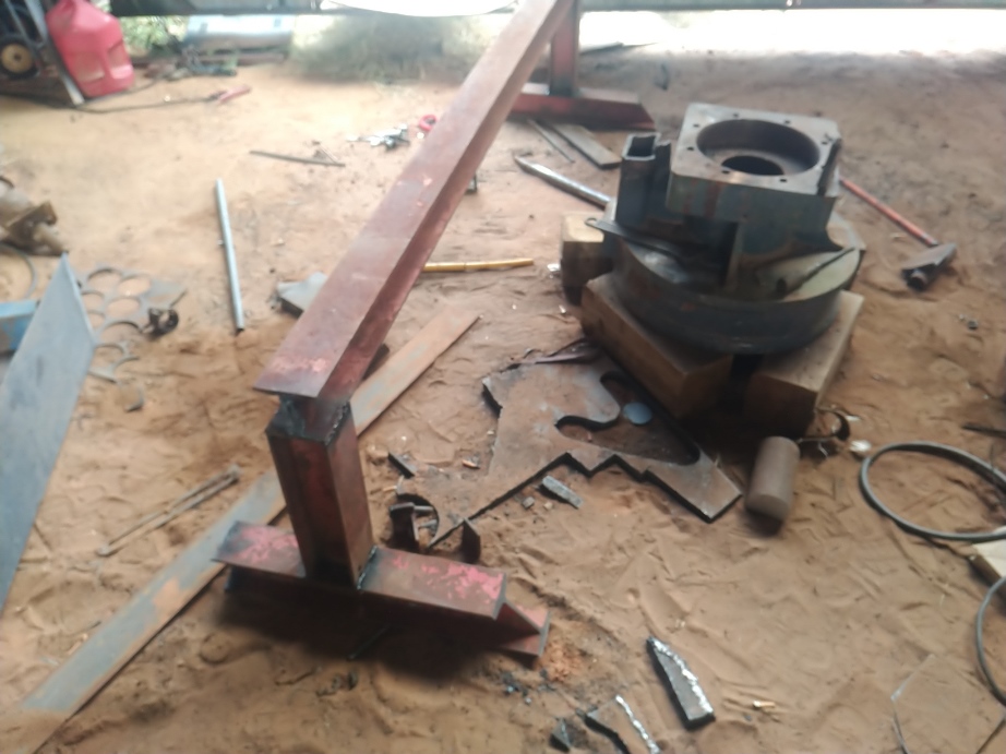
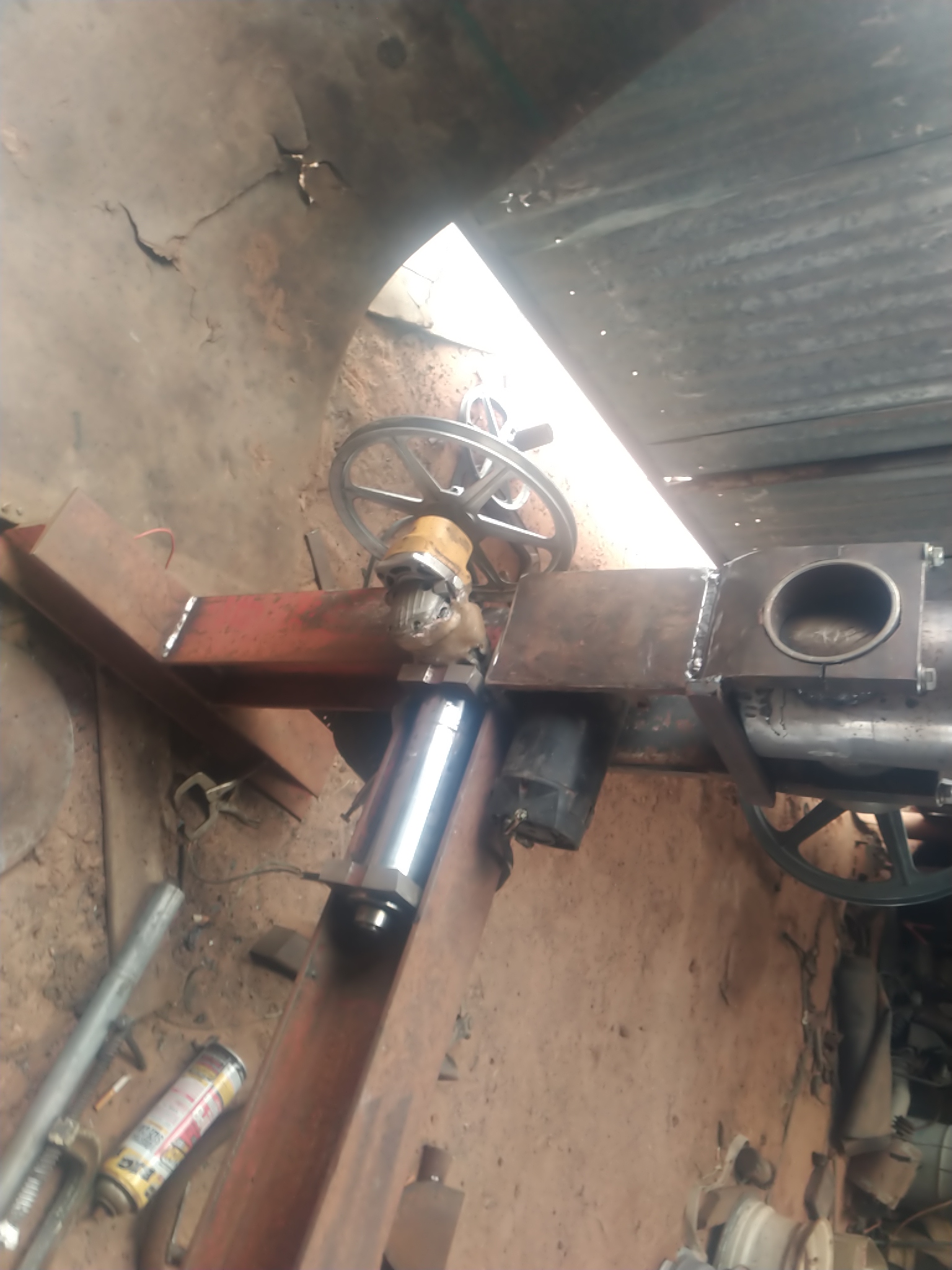
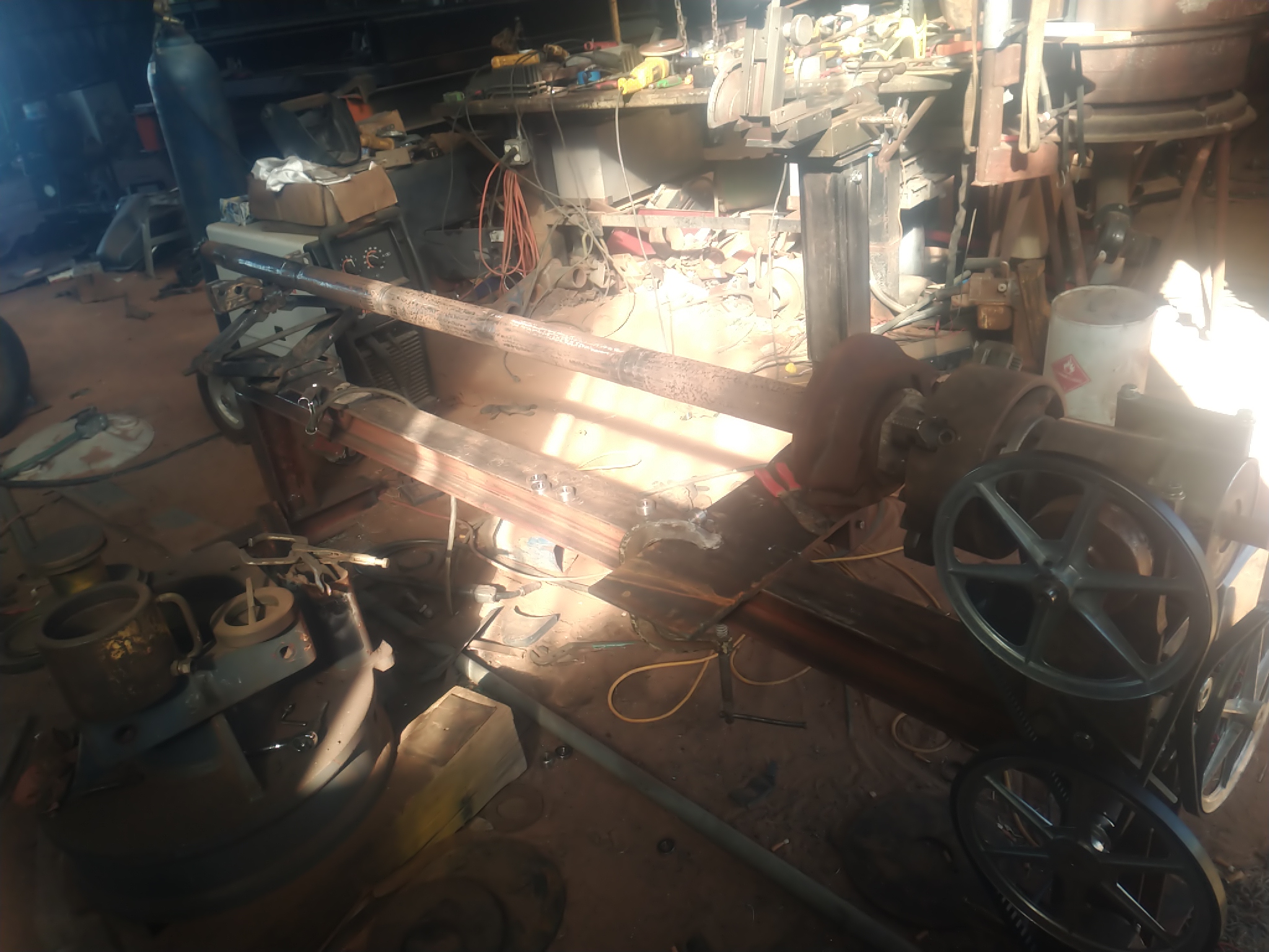
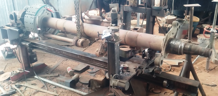
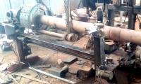
I started out a beam from a 1950's era globe 4 post lift as the frame.
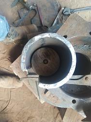
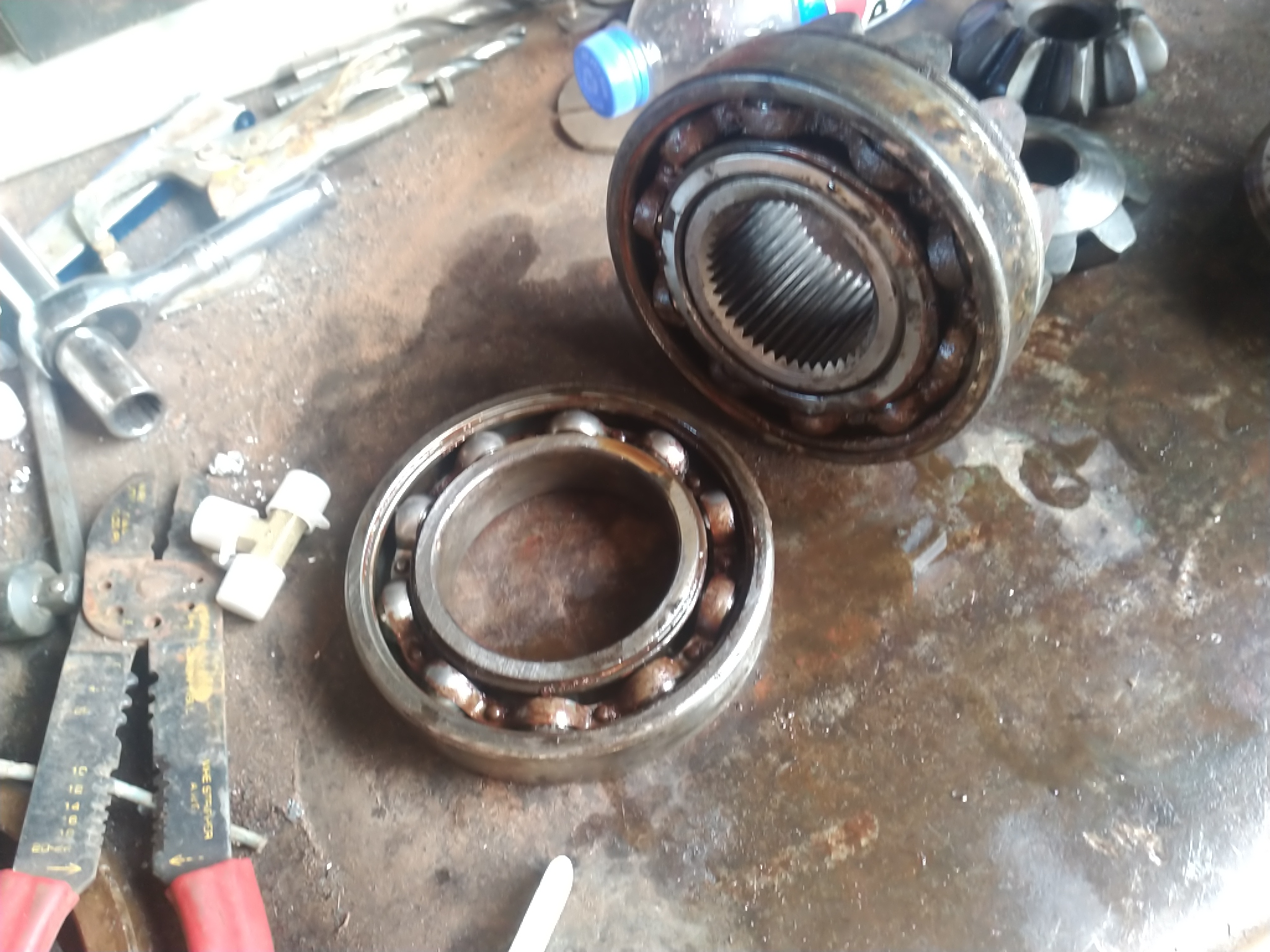
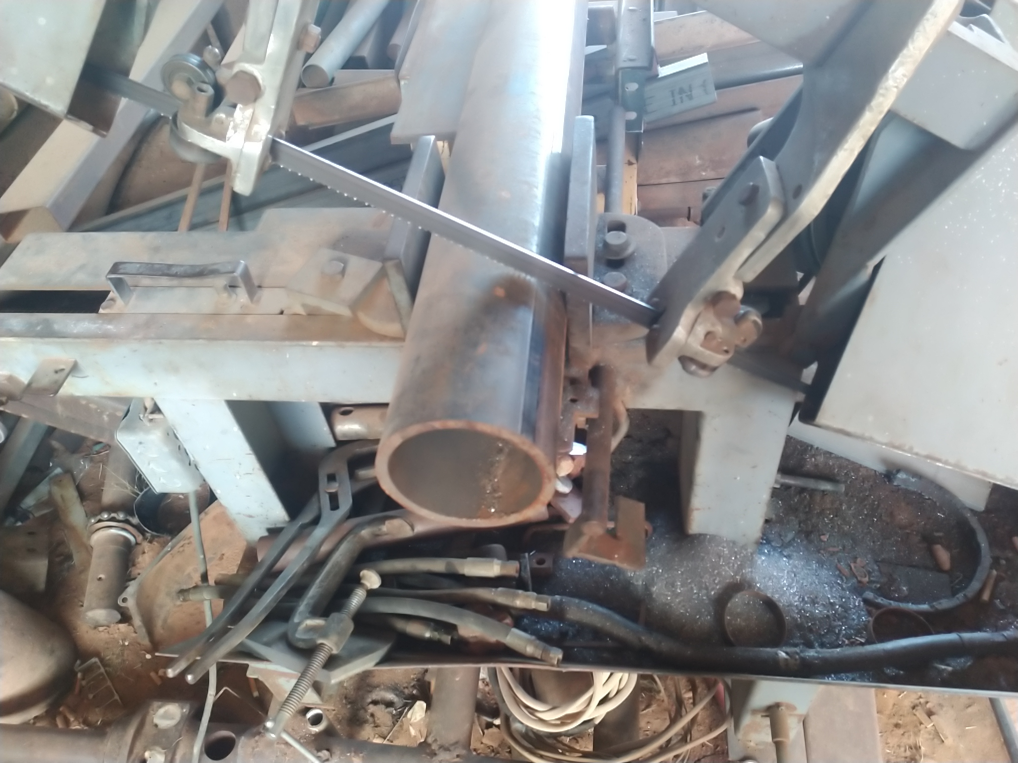
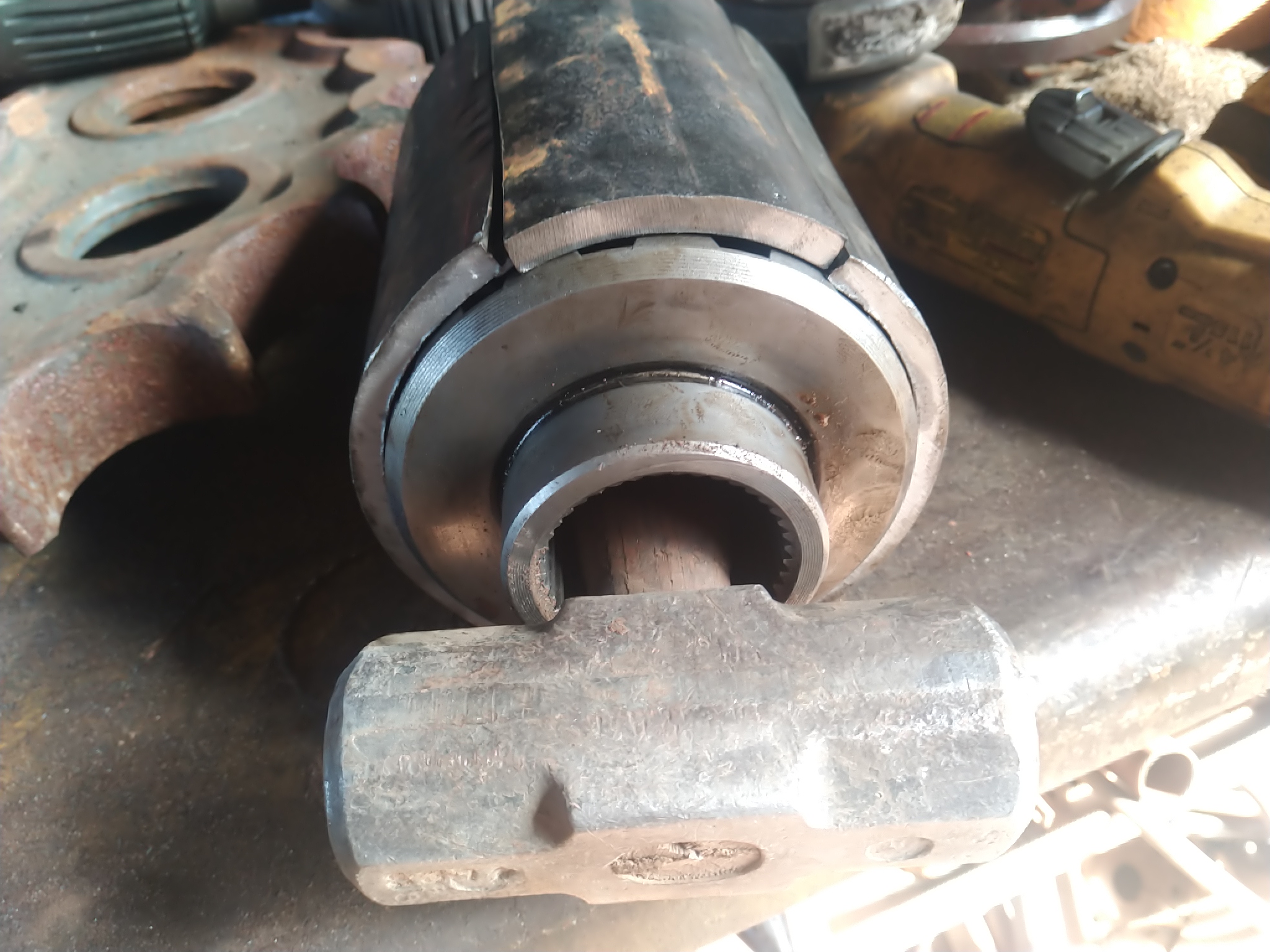
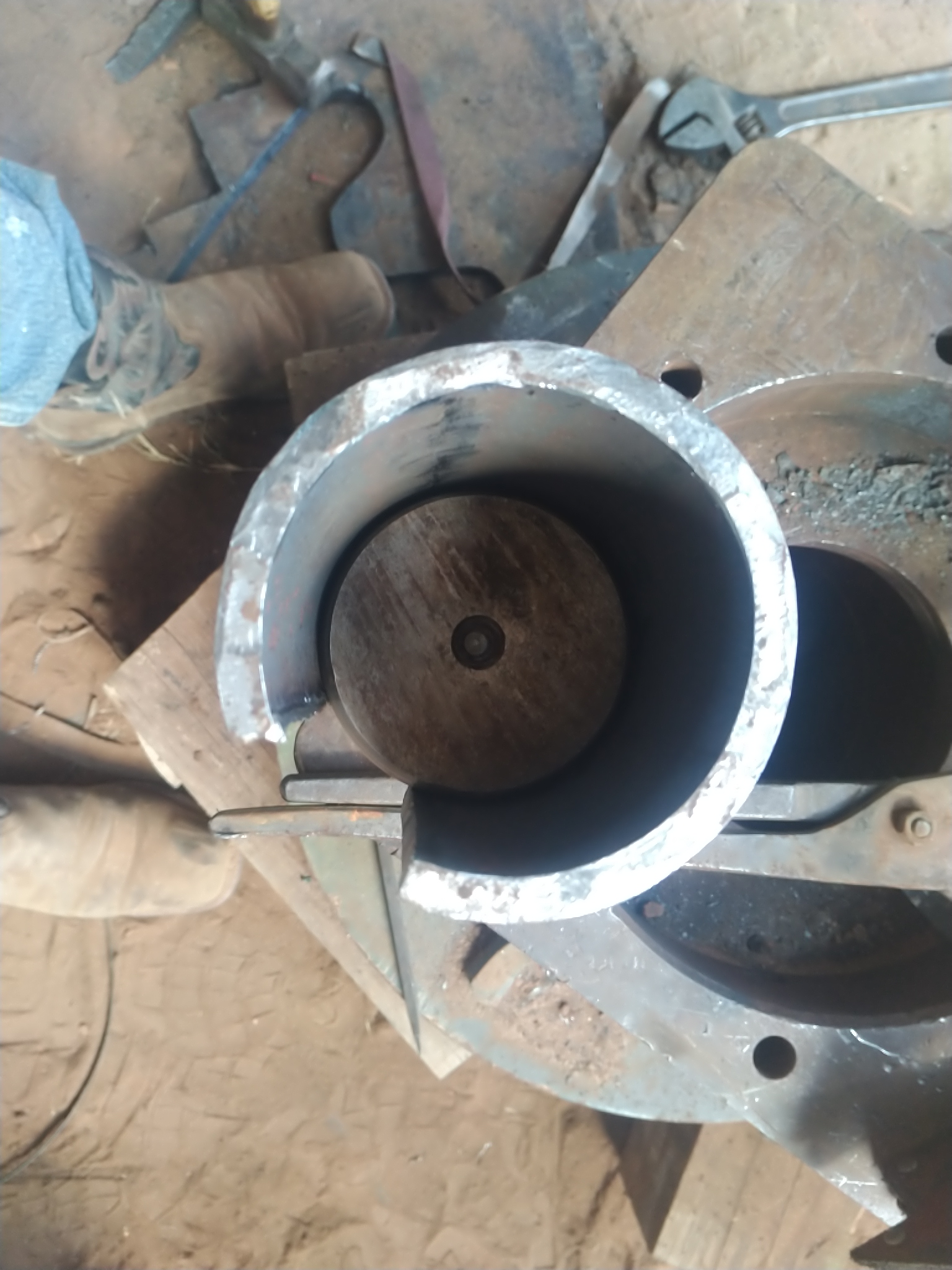
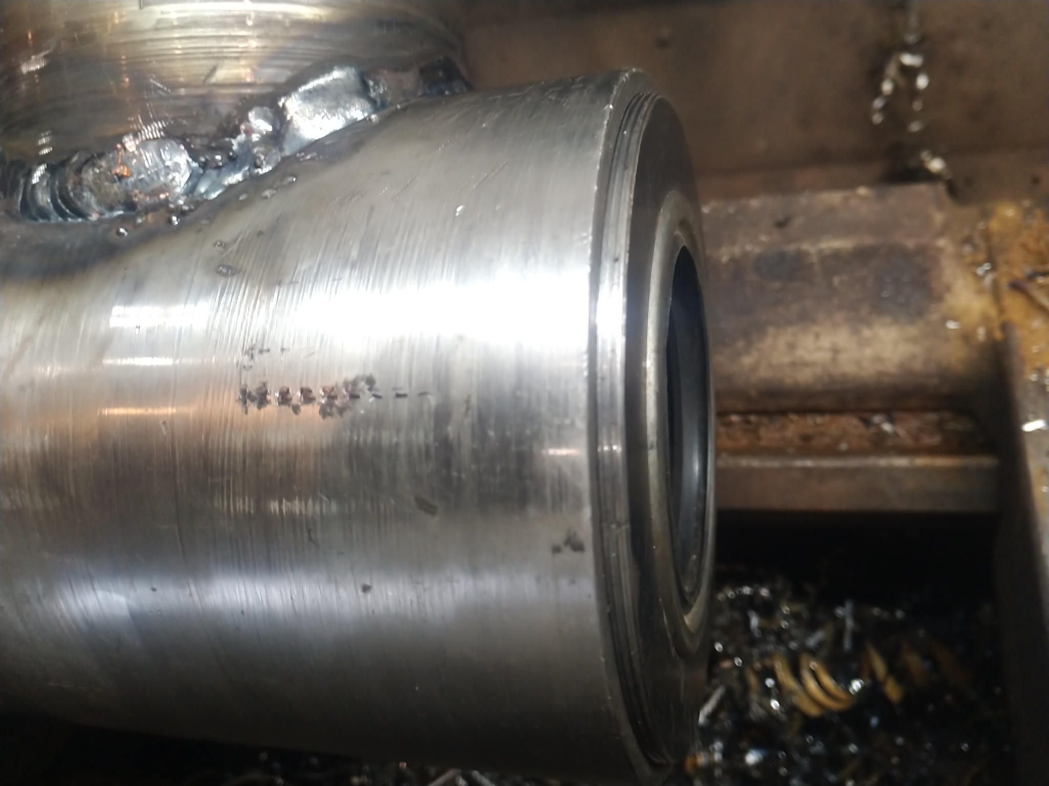
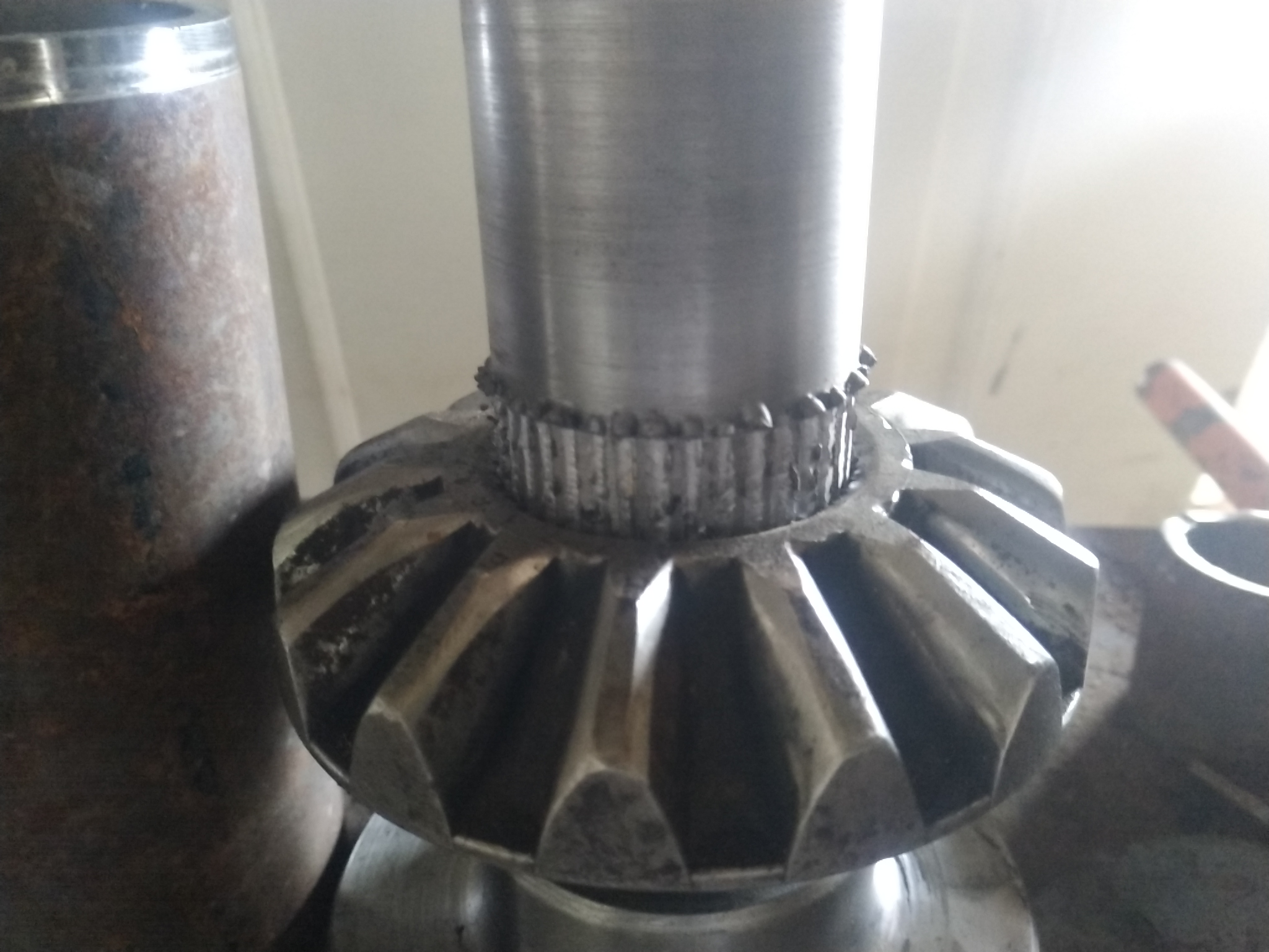
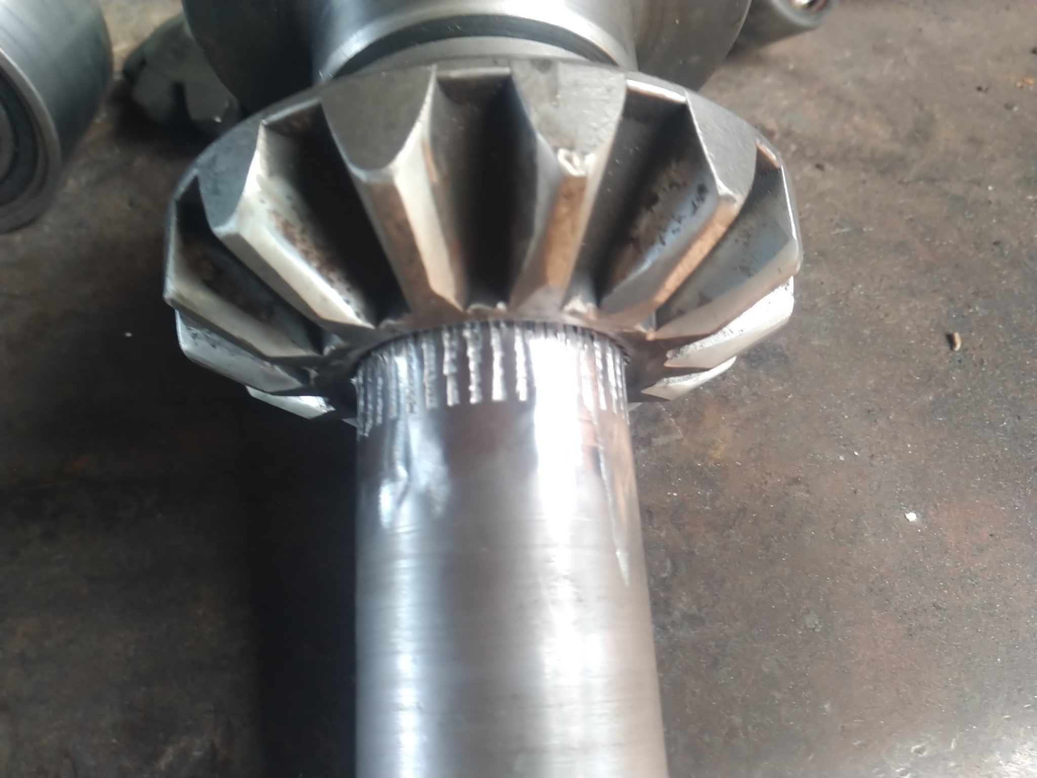
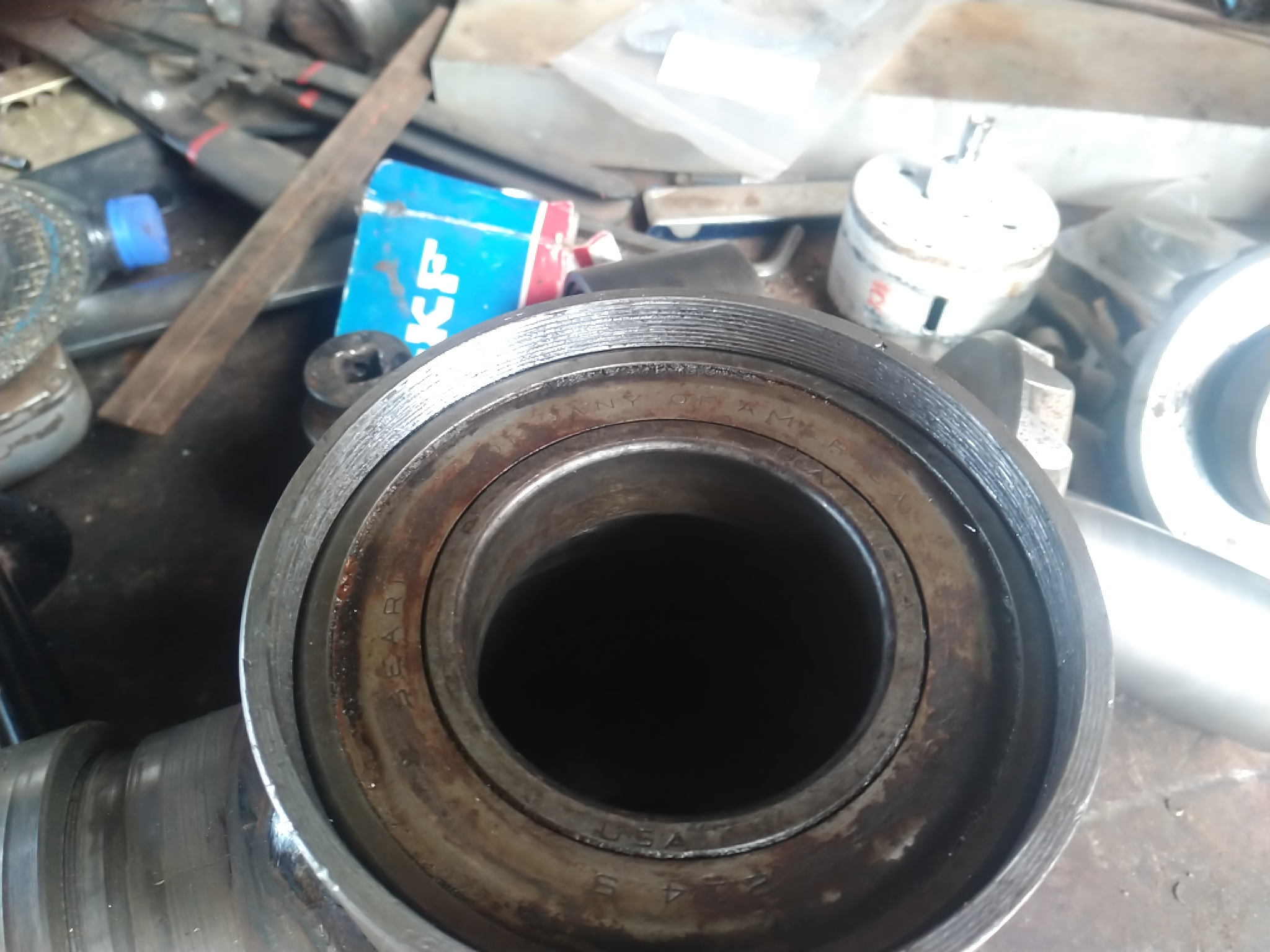
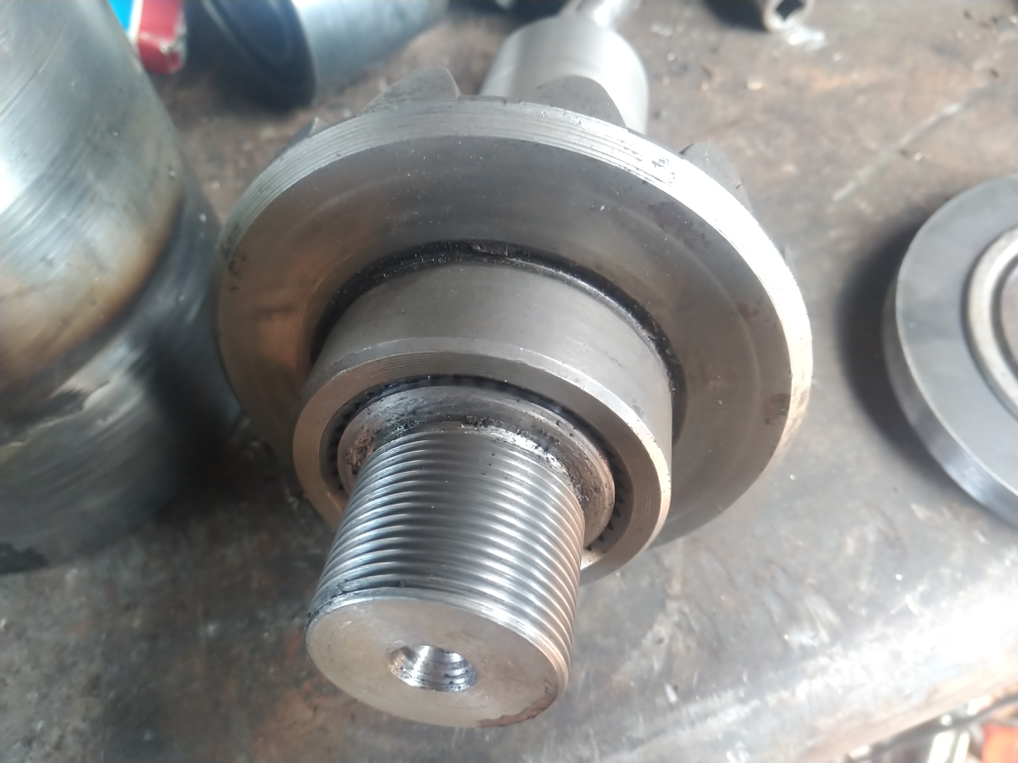
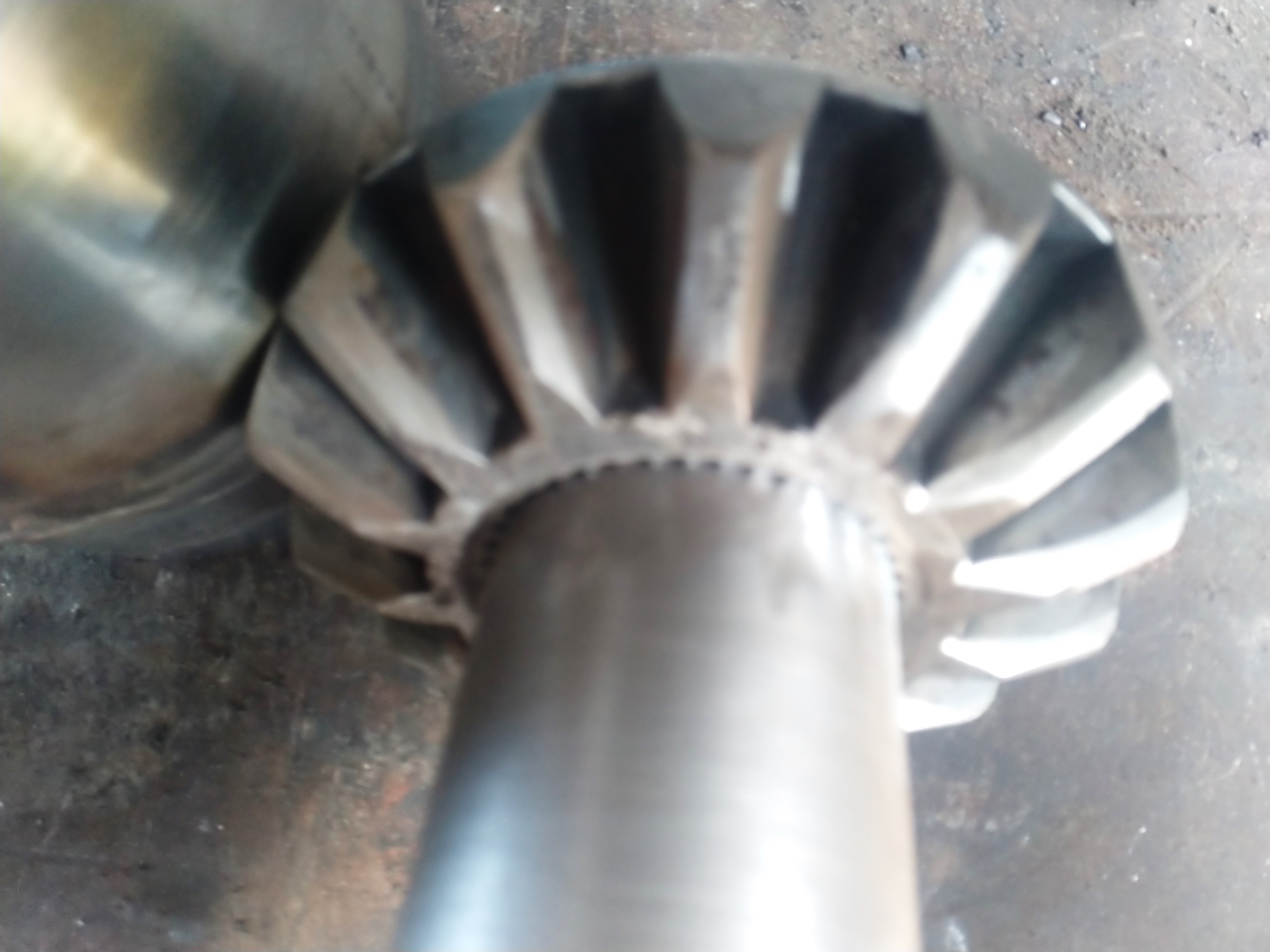
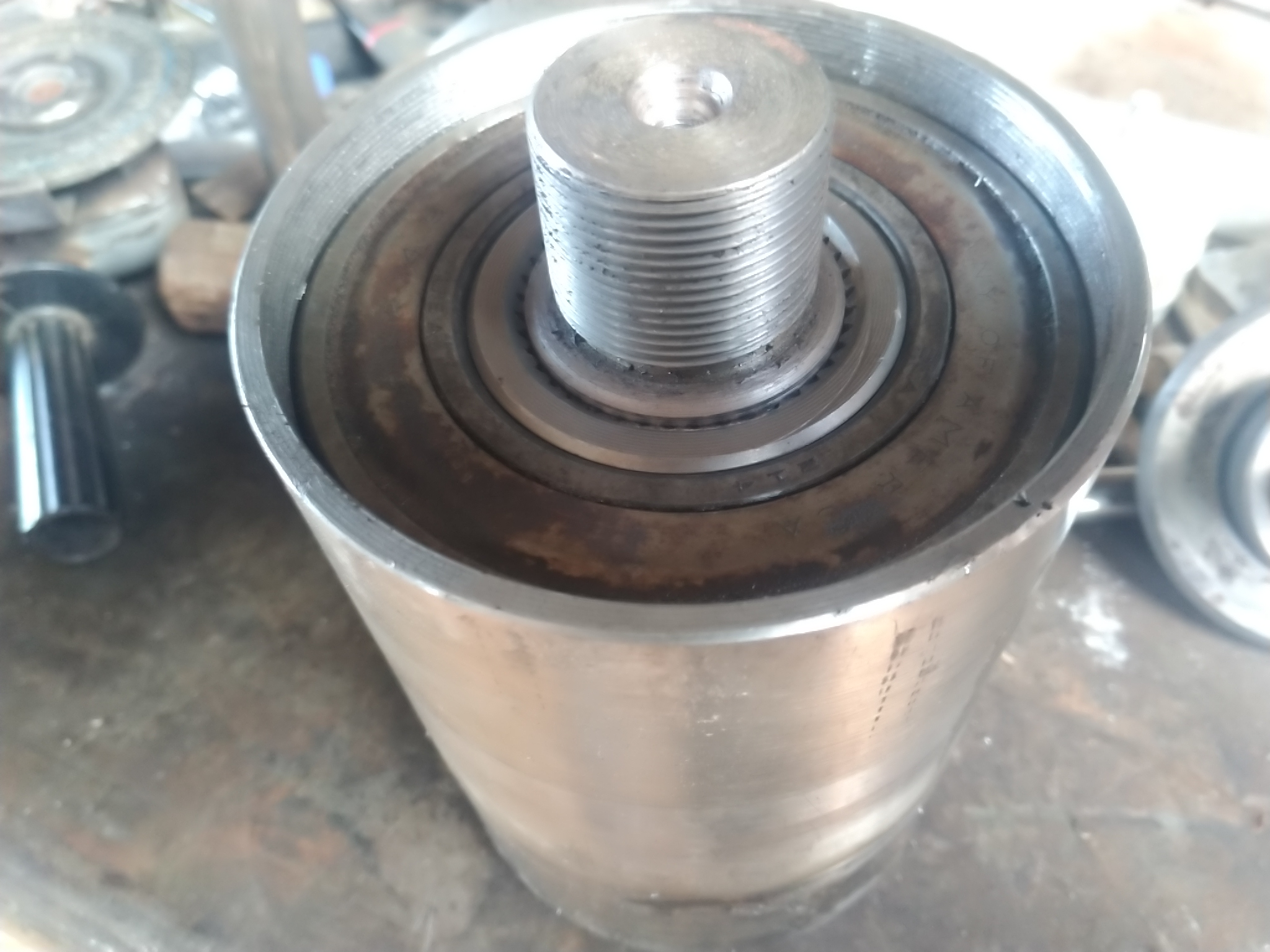
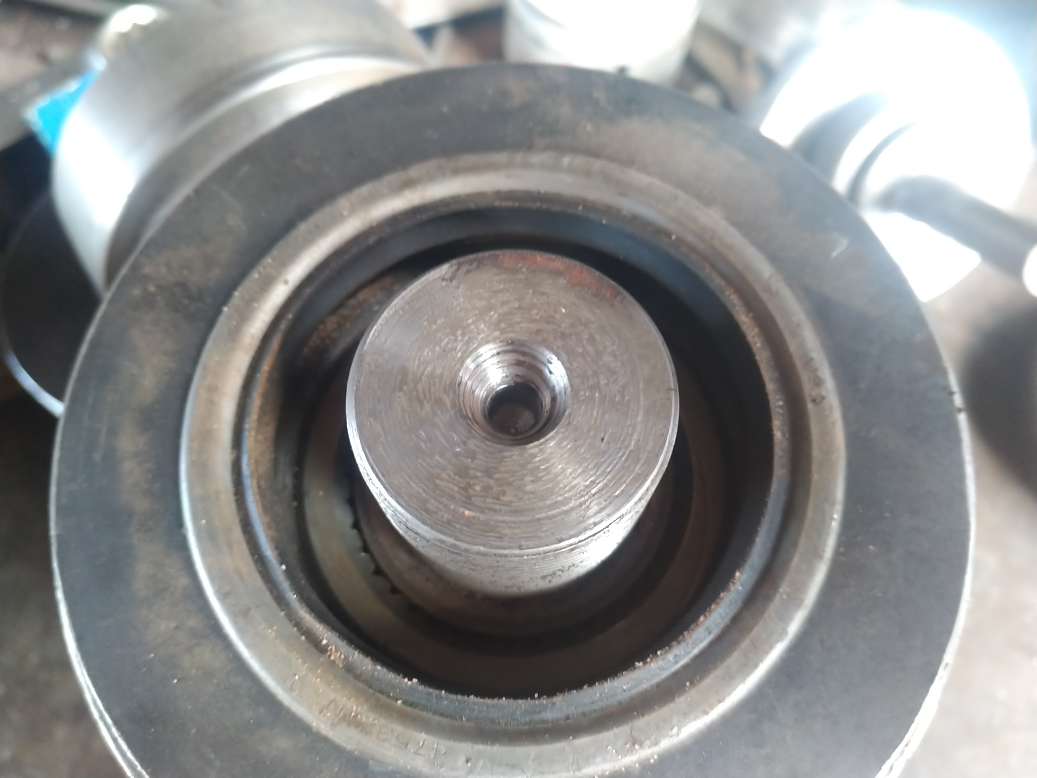
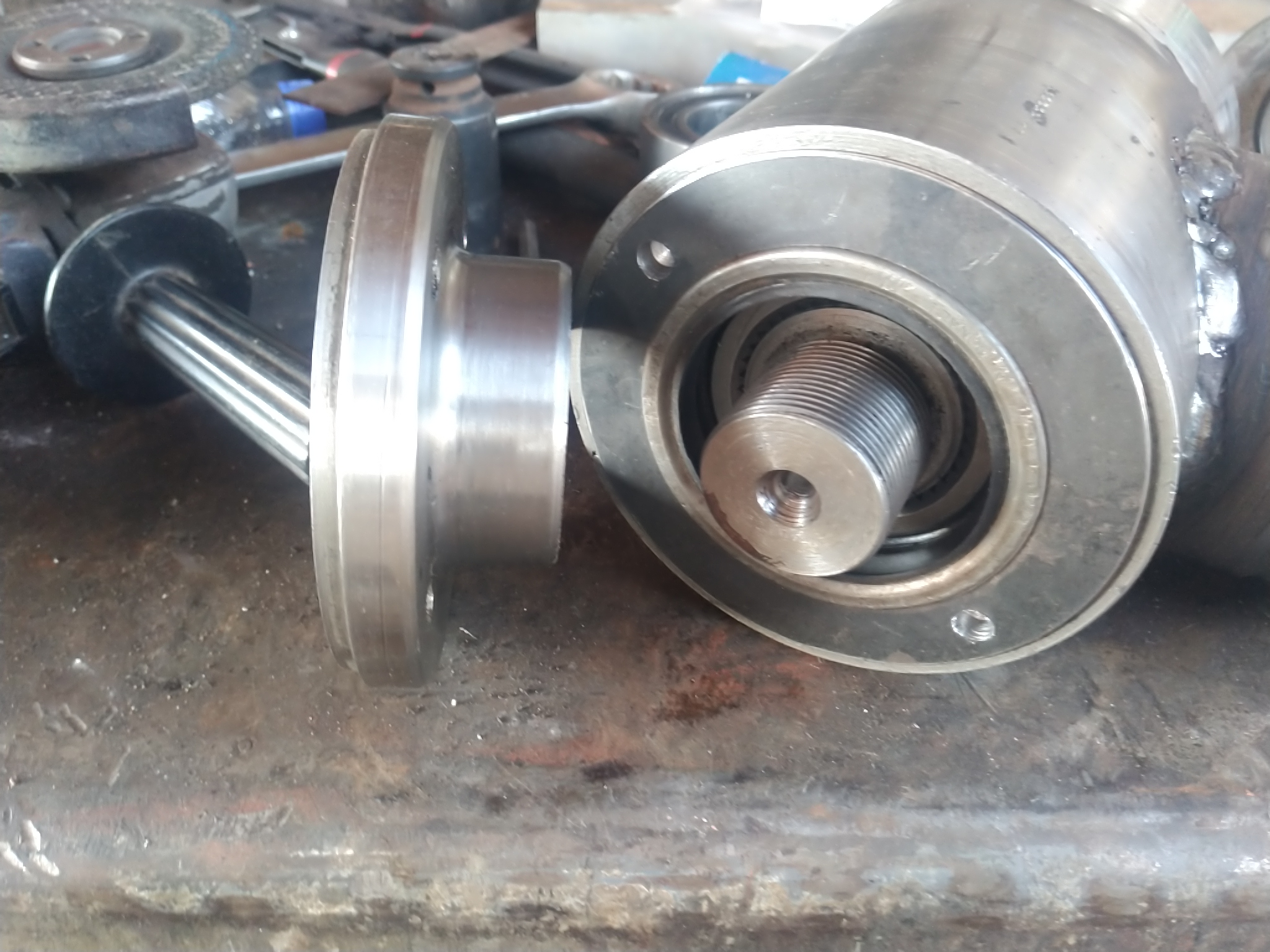
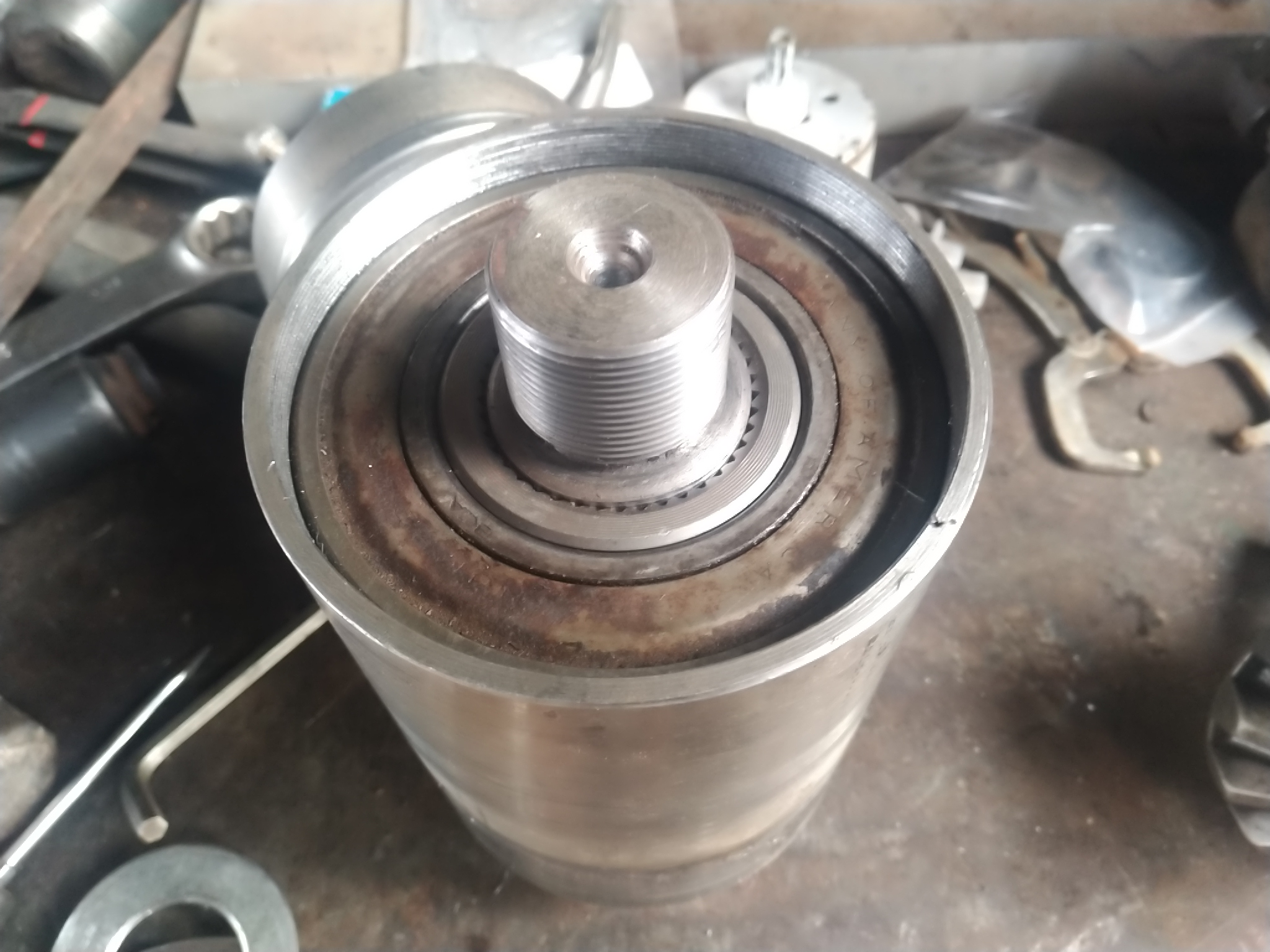
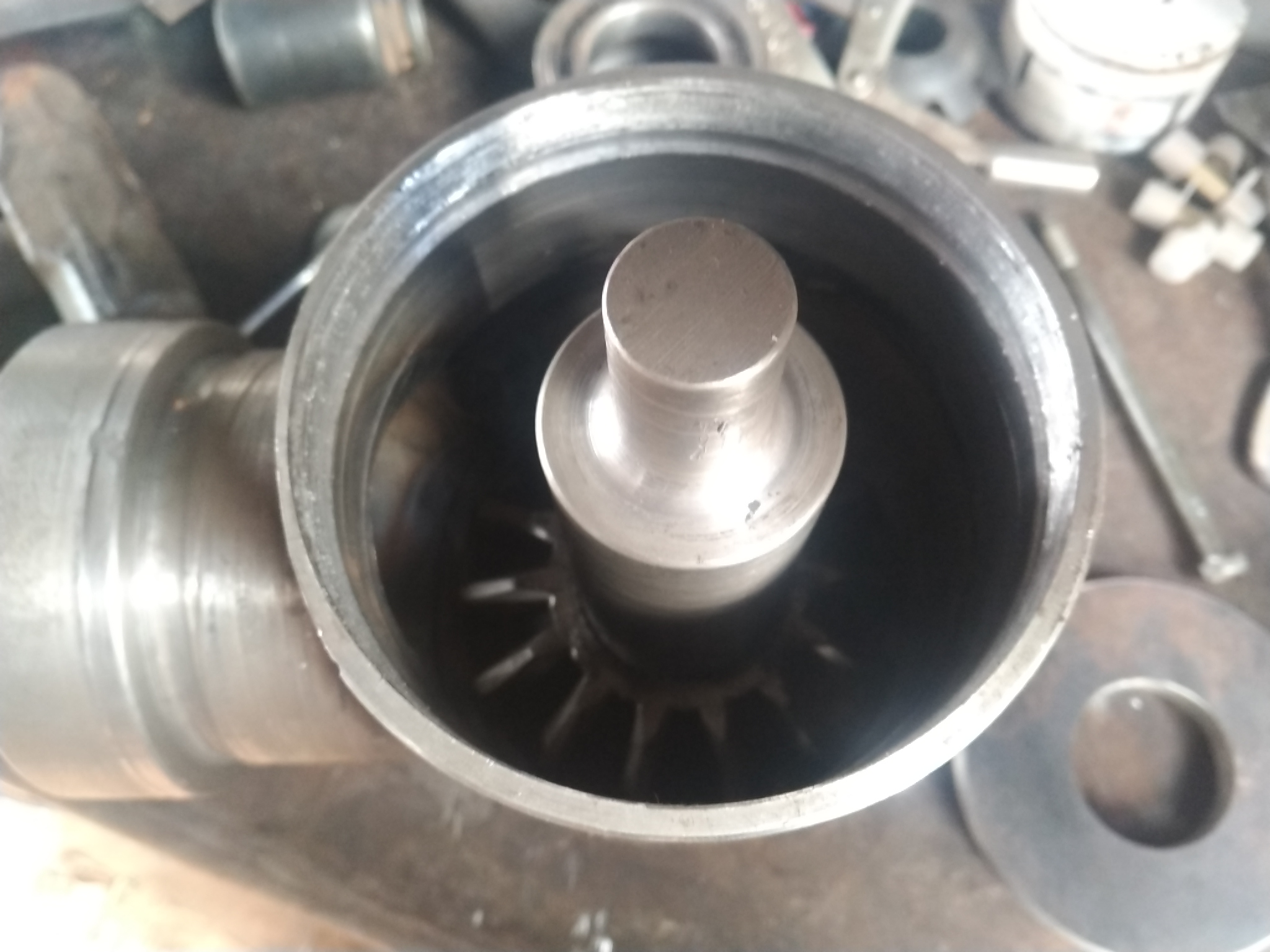
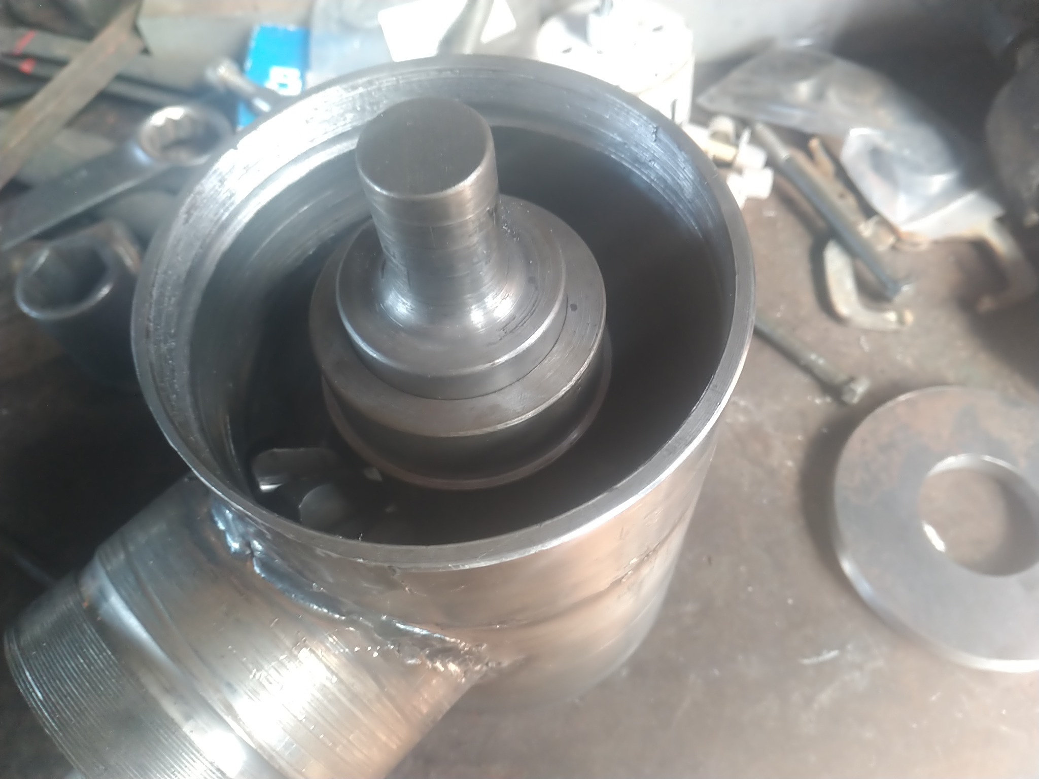
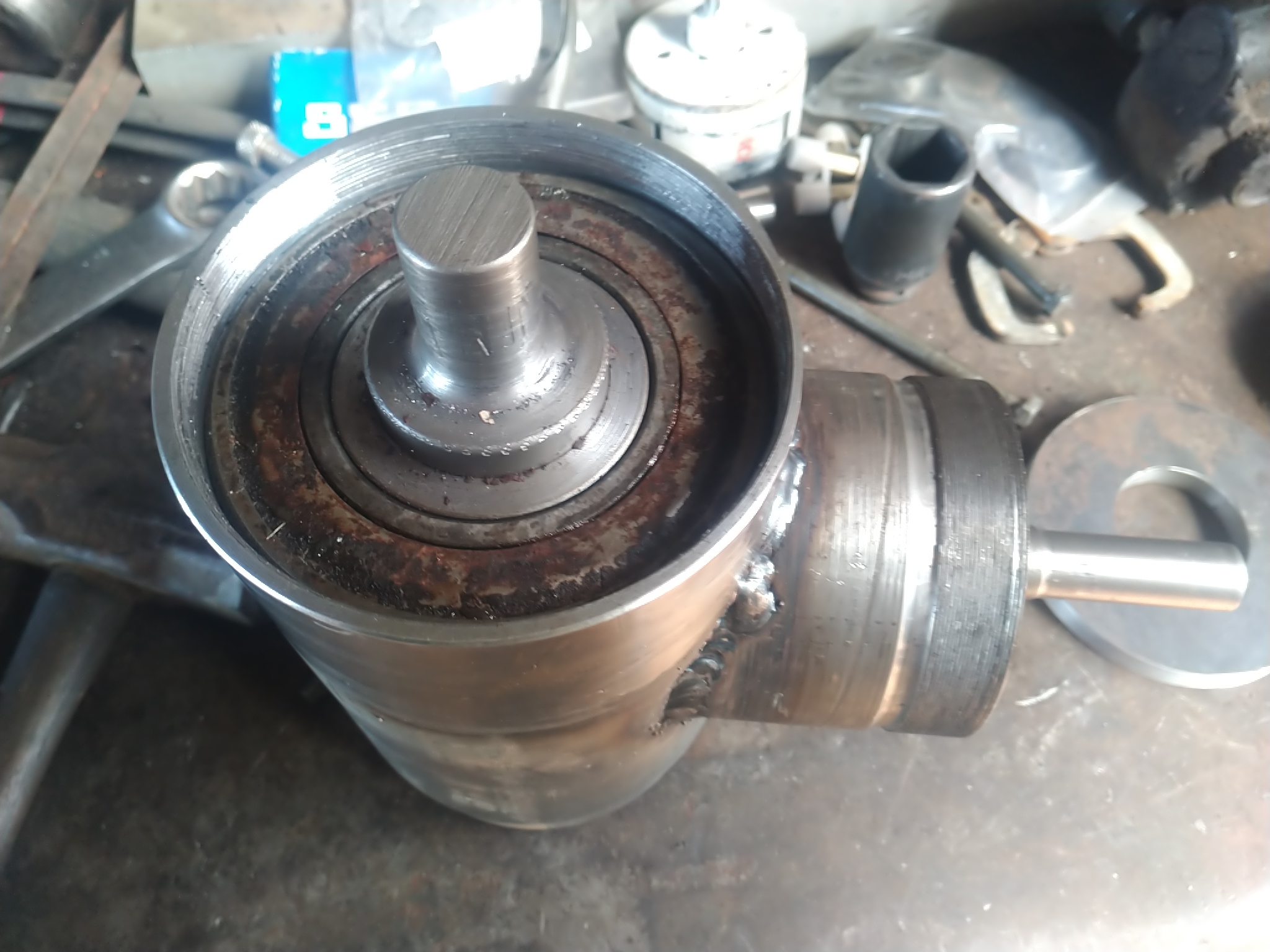
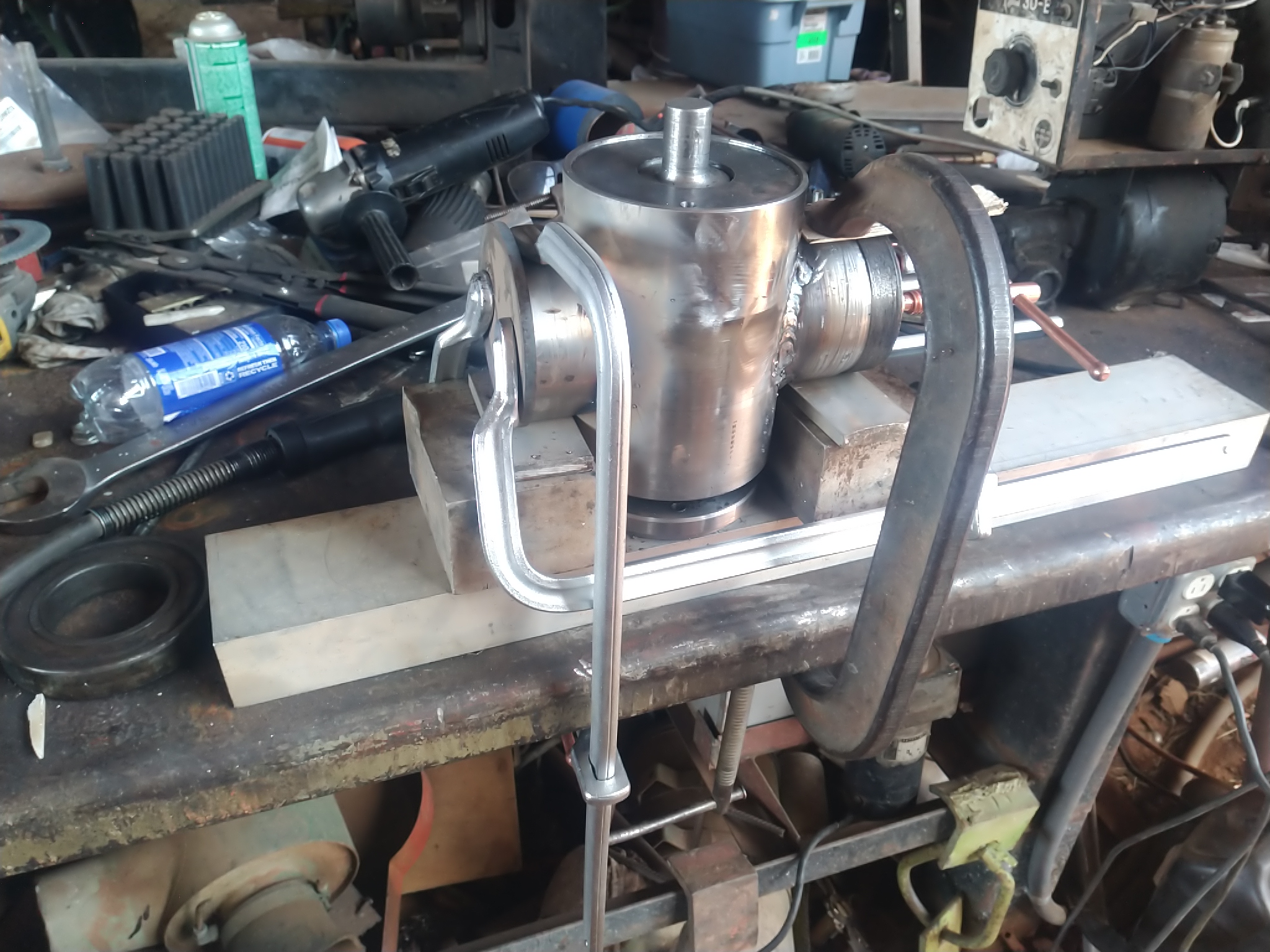
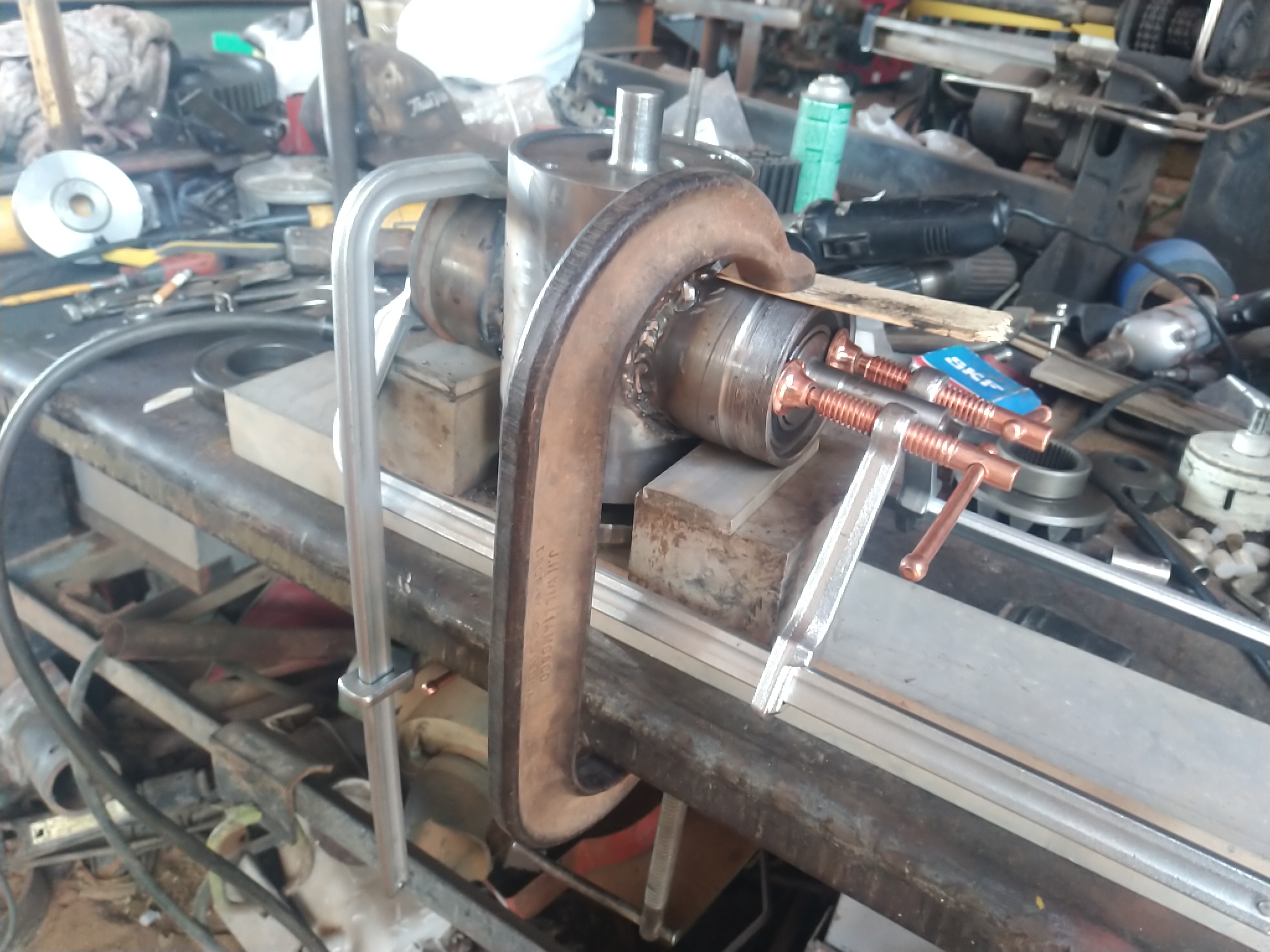
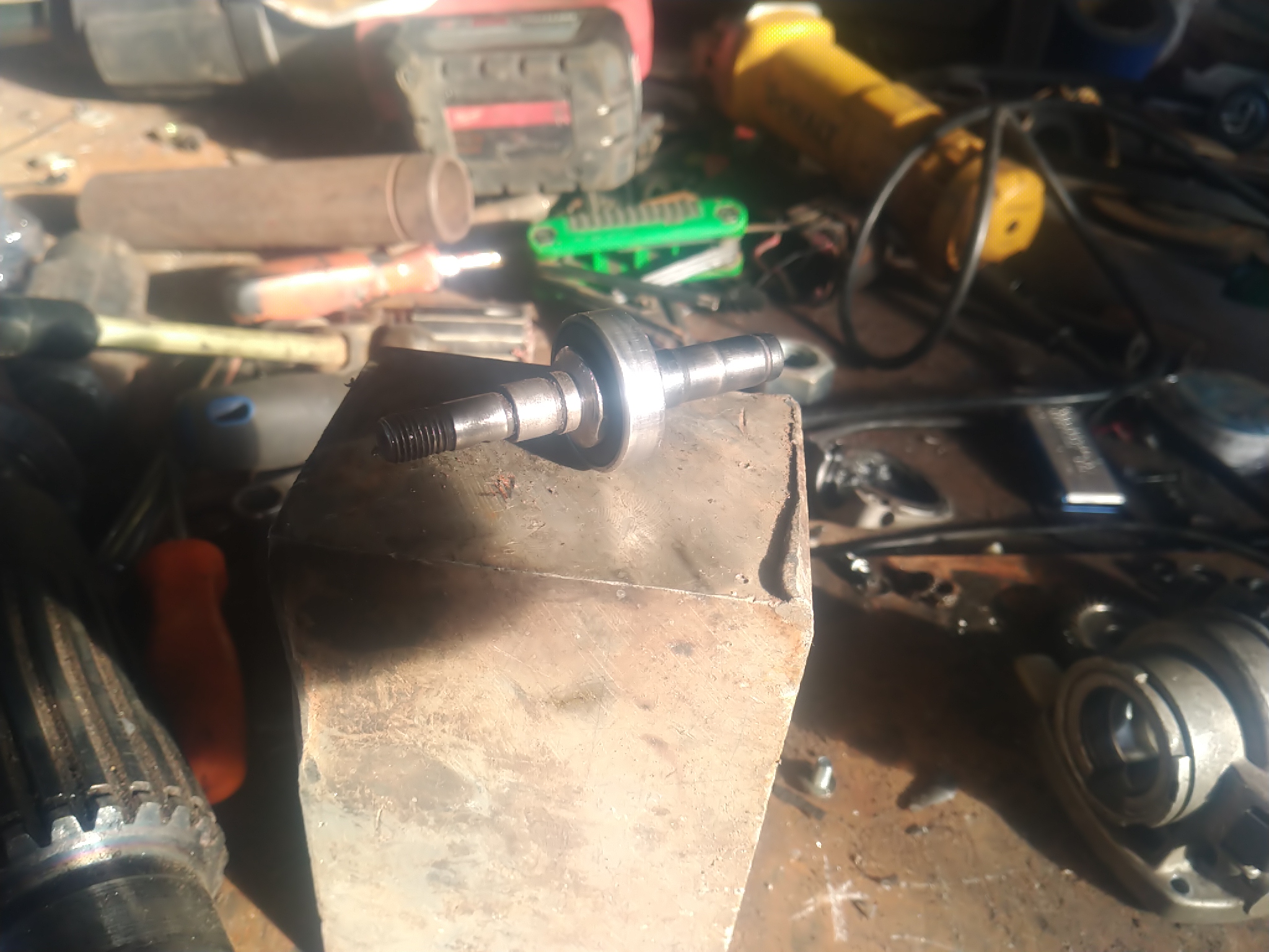
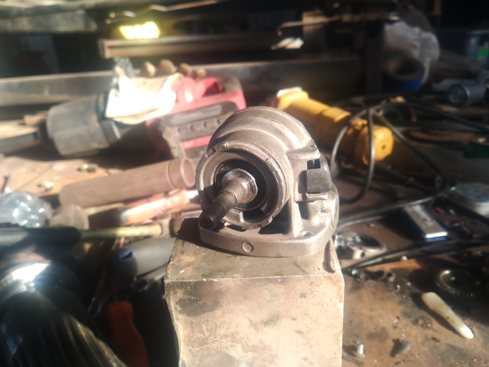
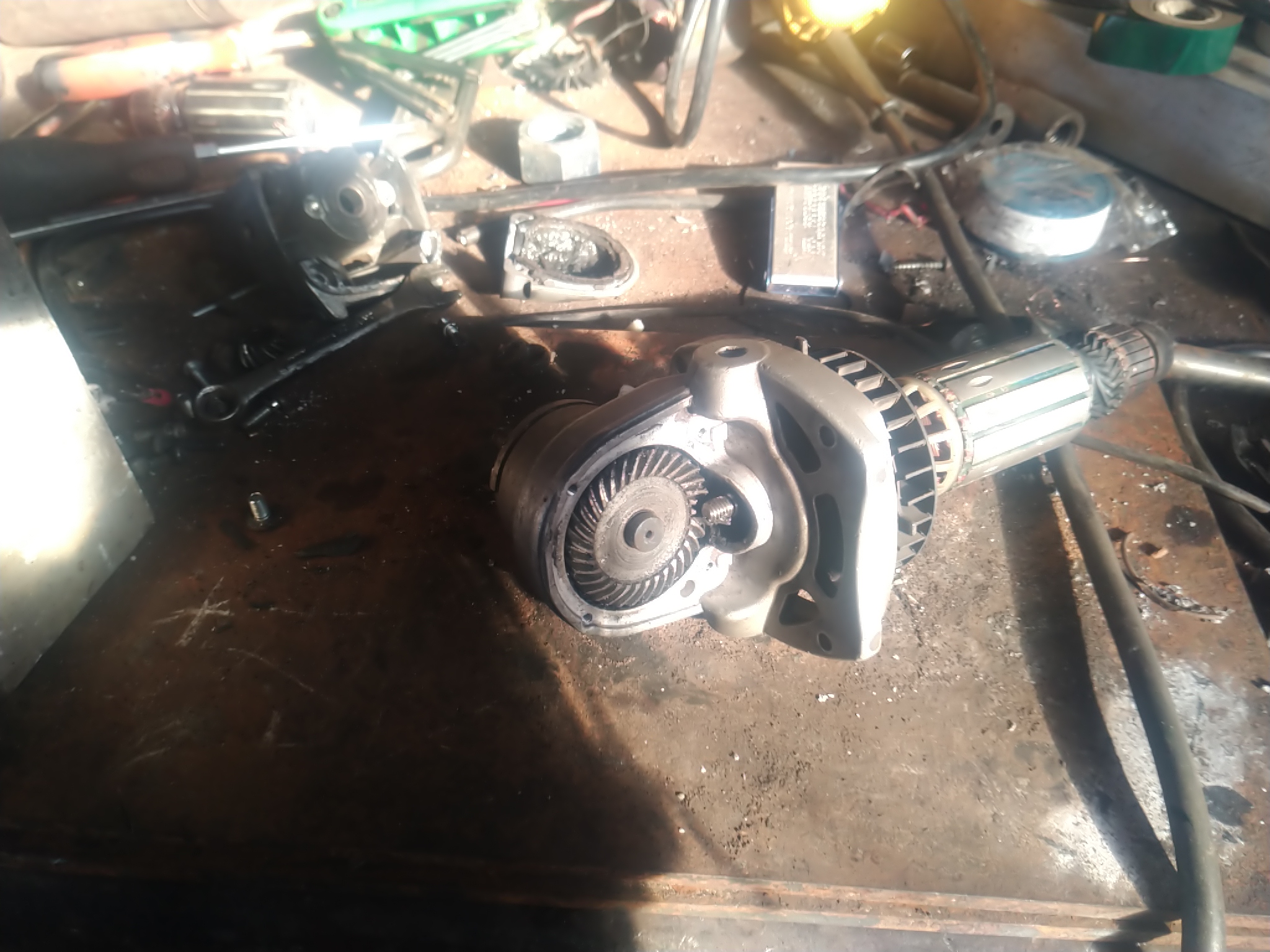
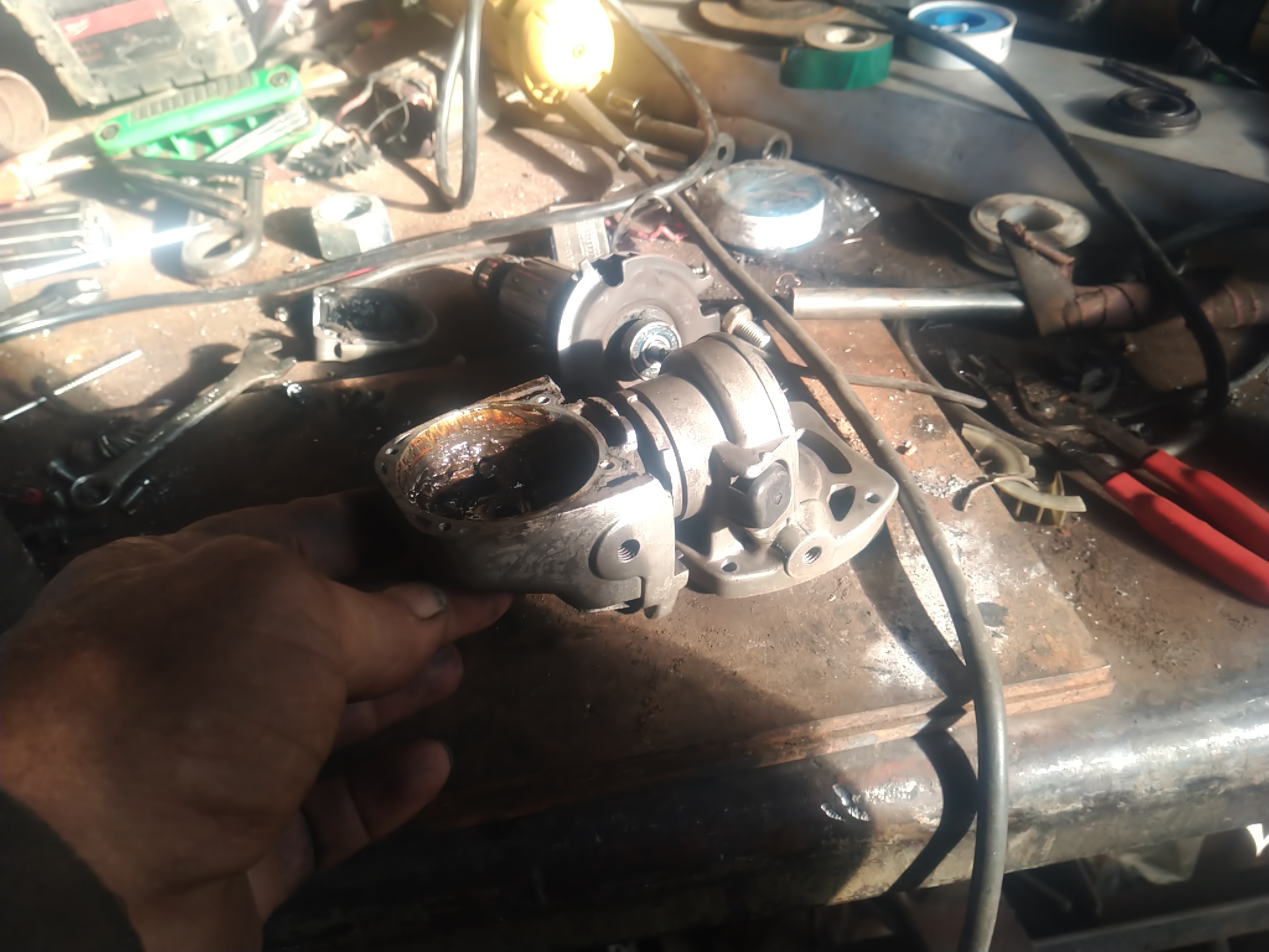
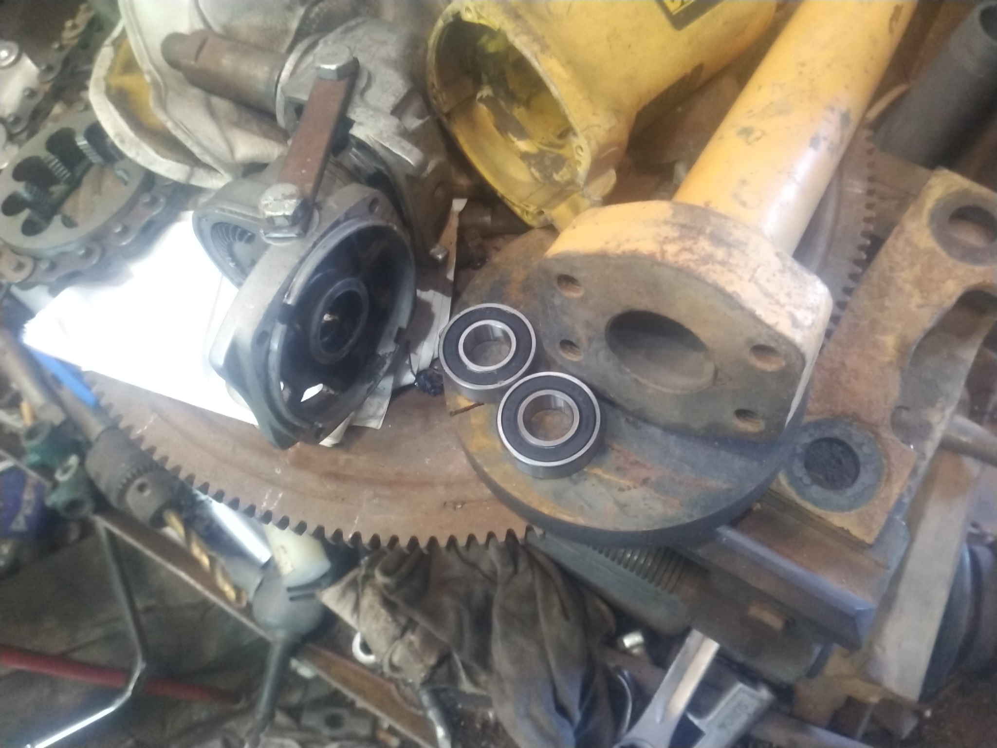
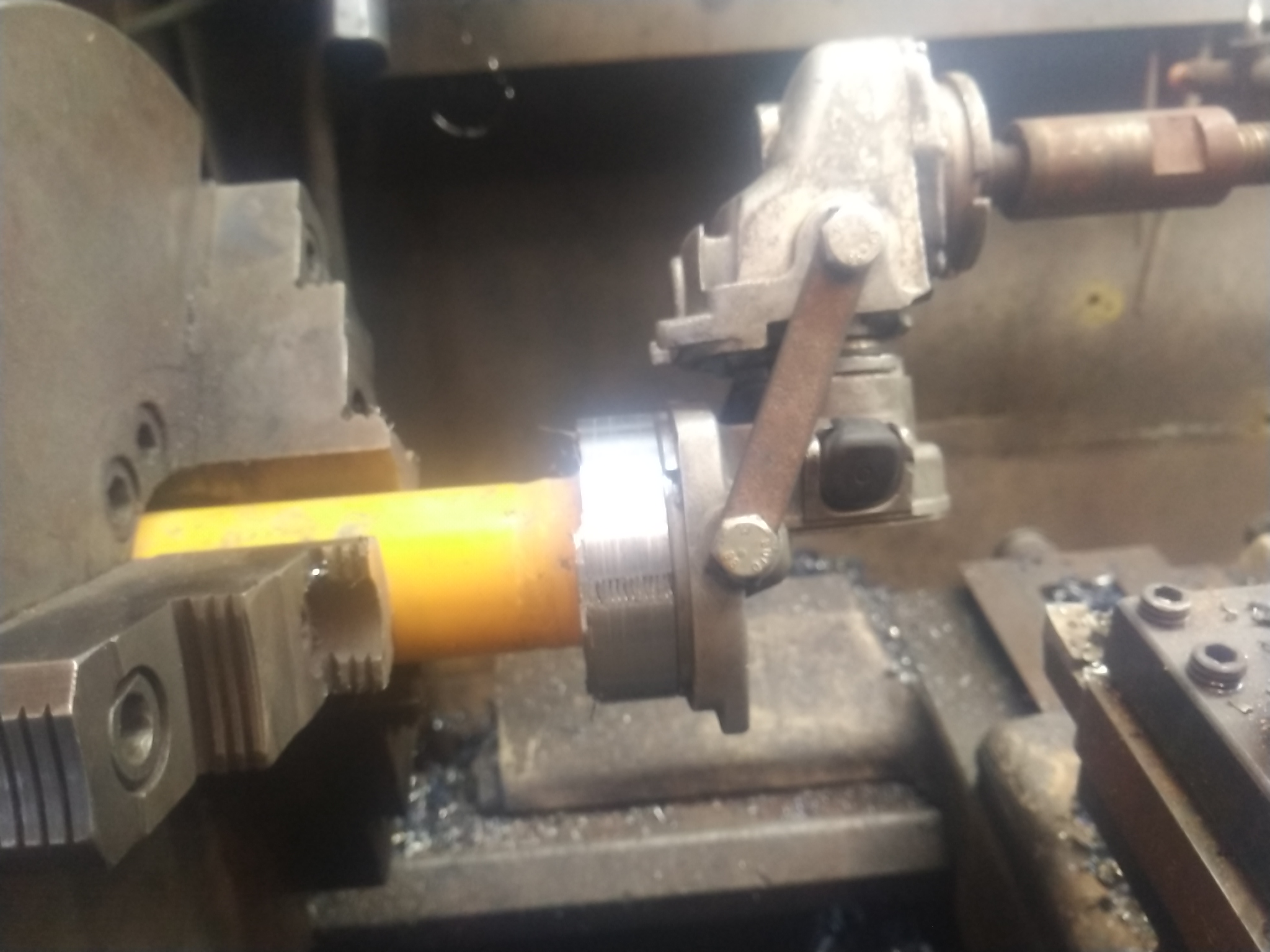
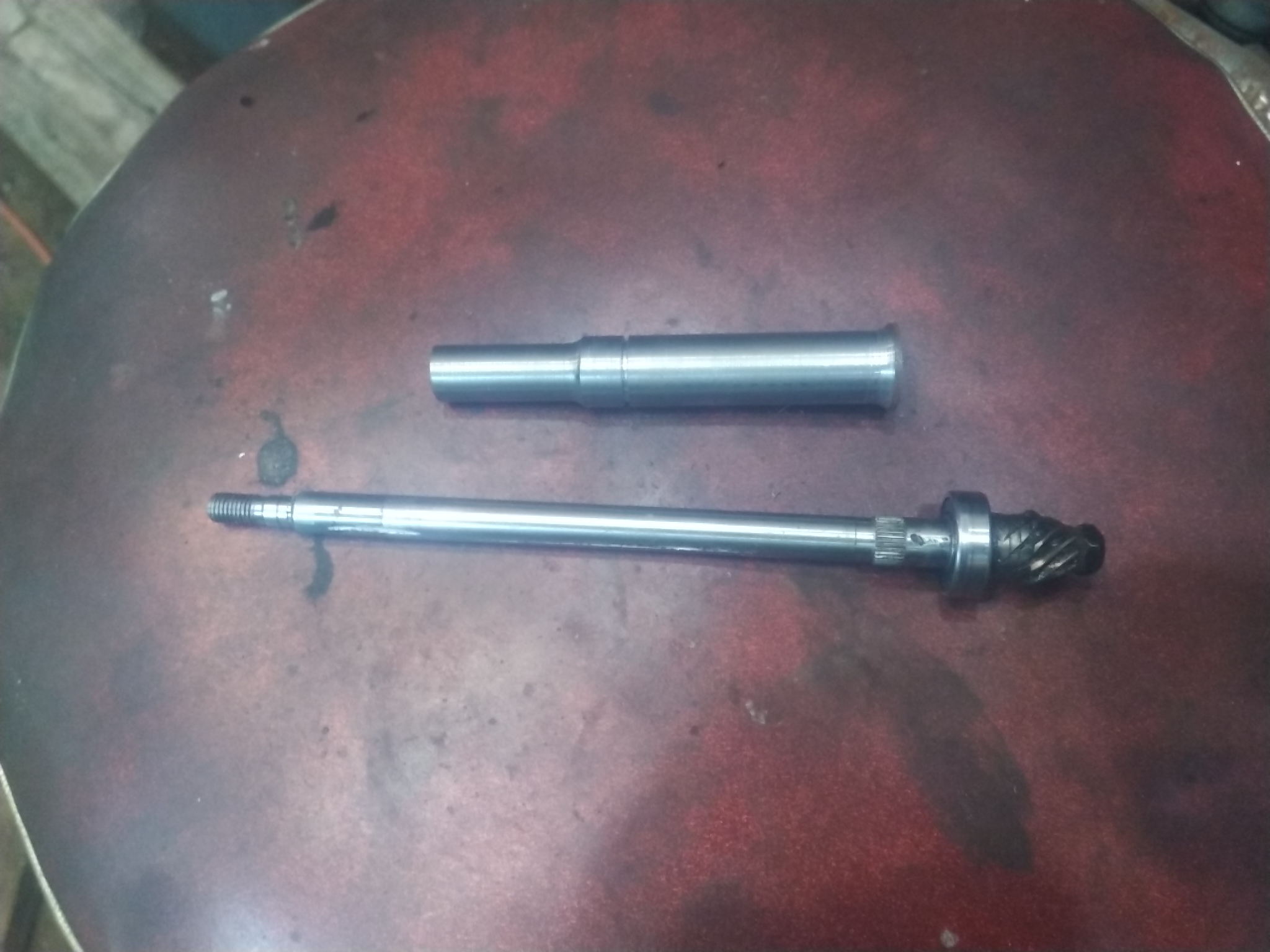
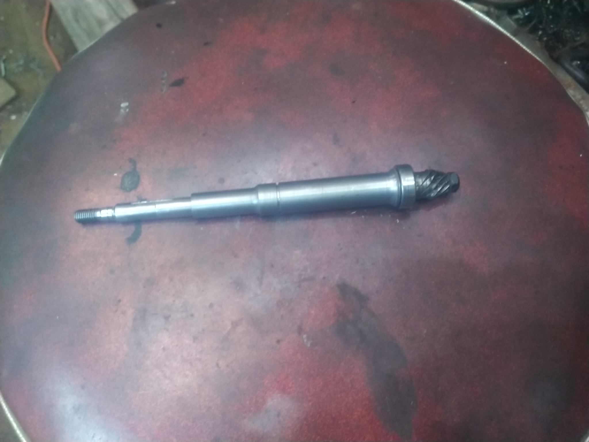
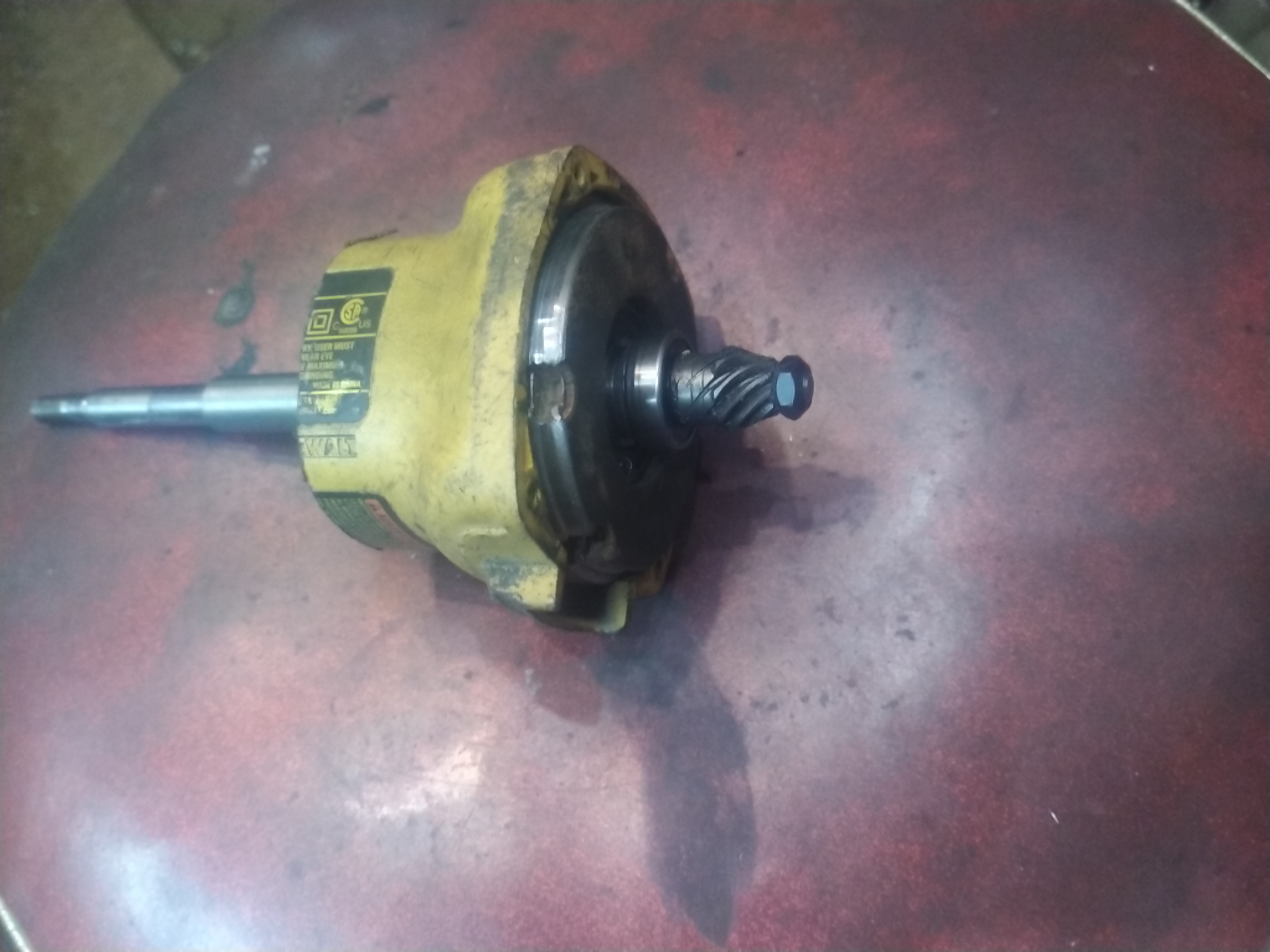
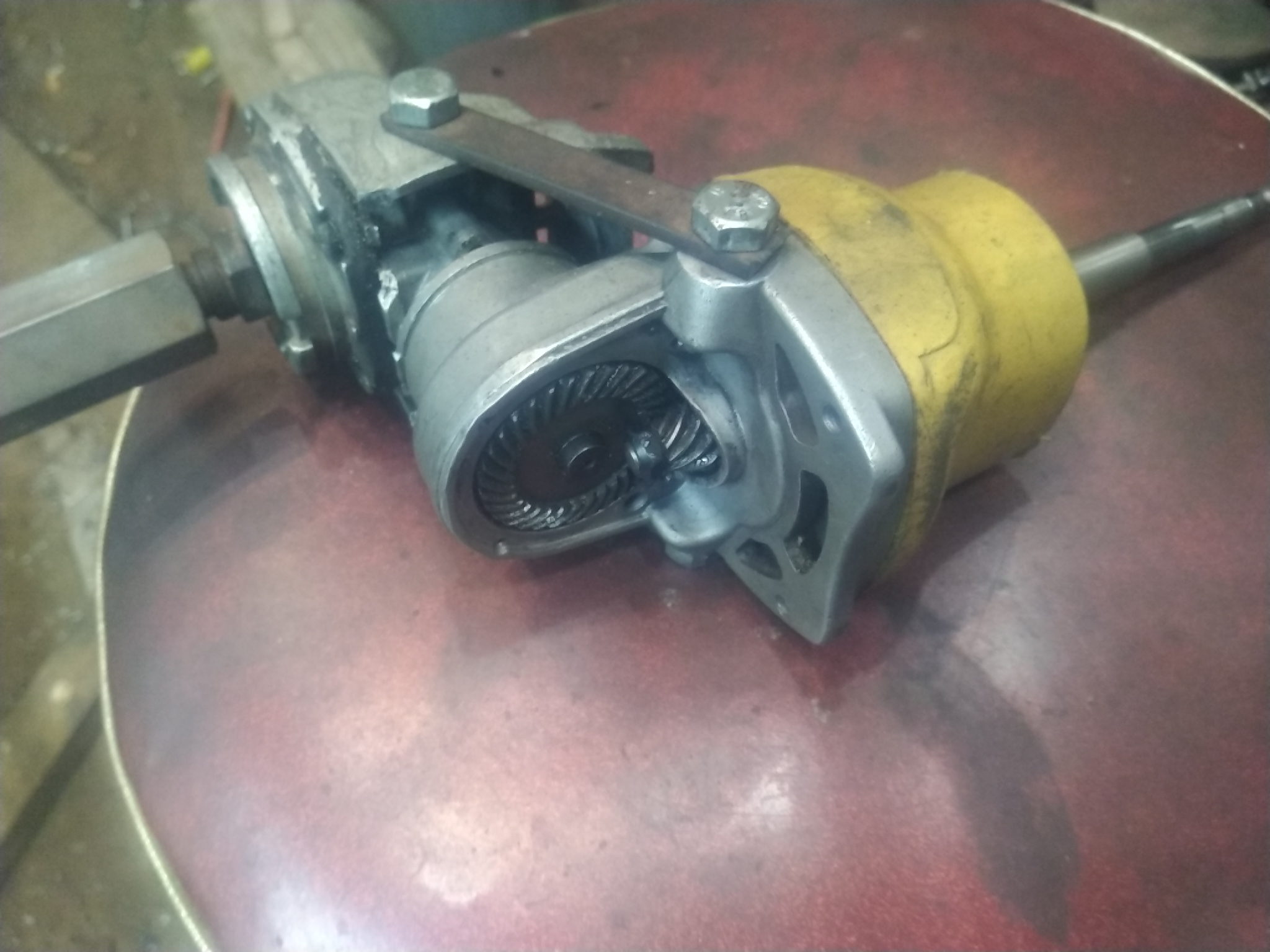
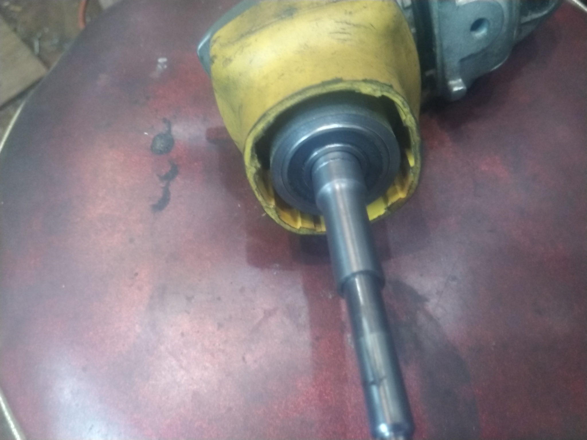
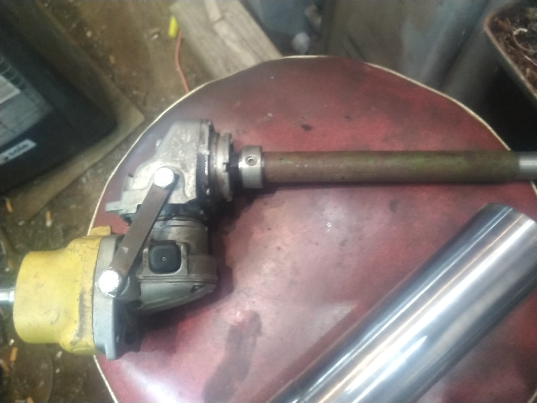
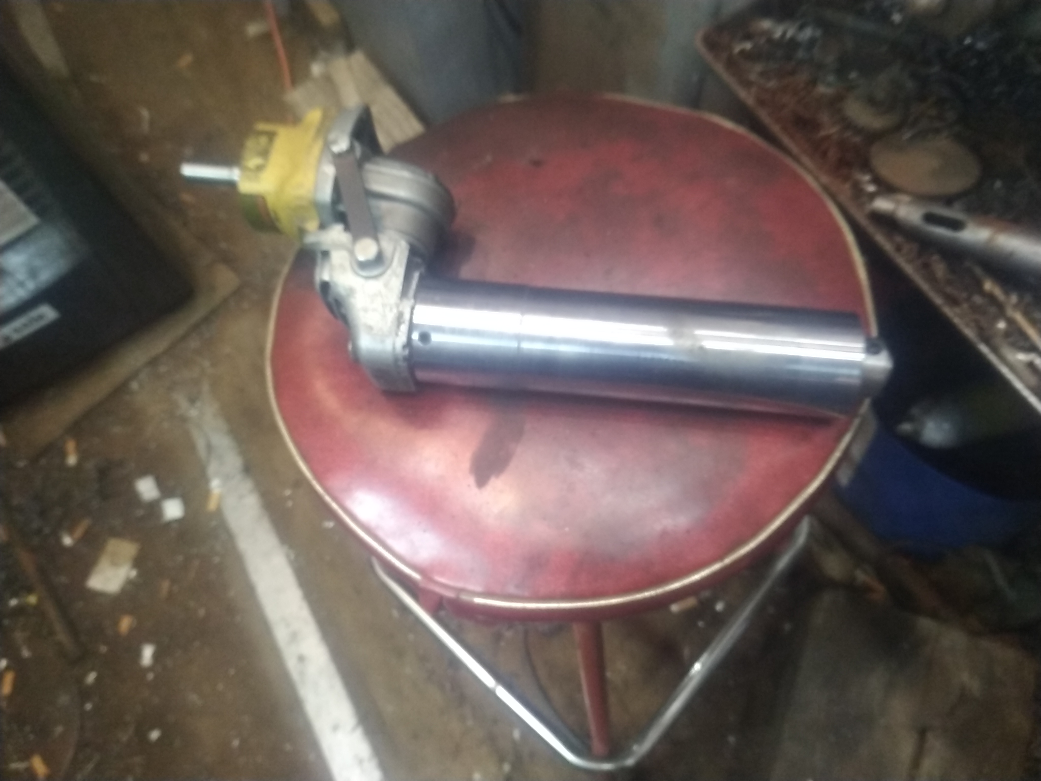
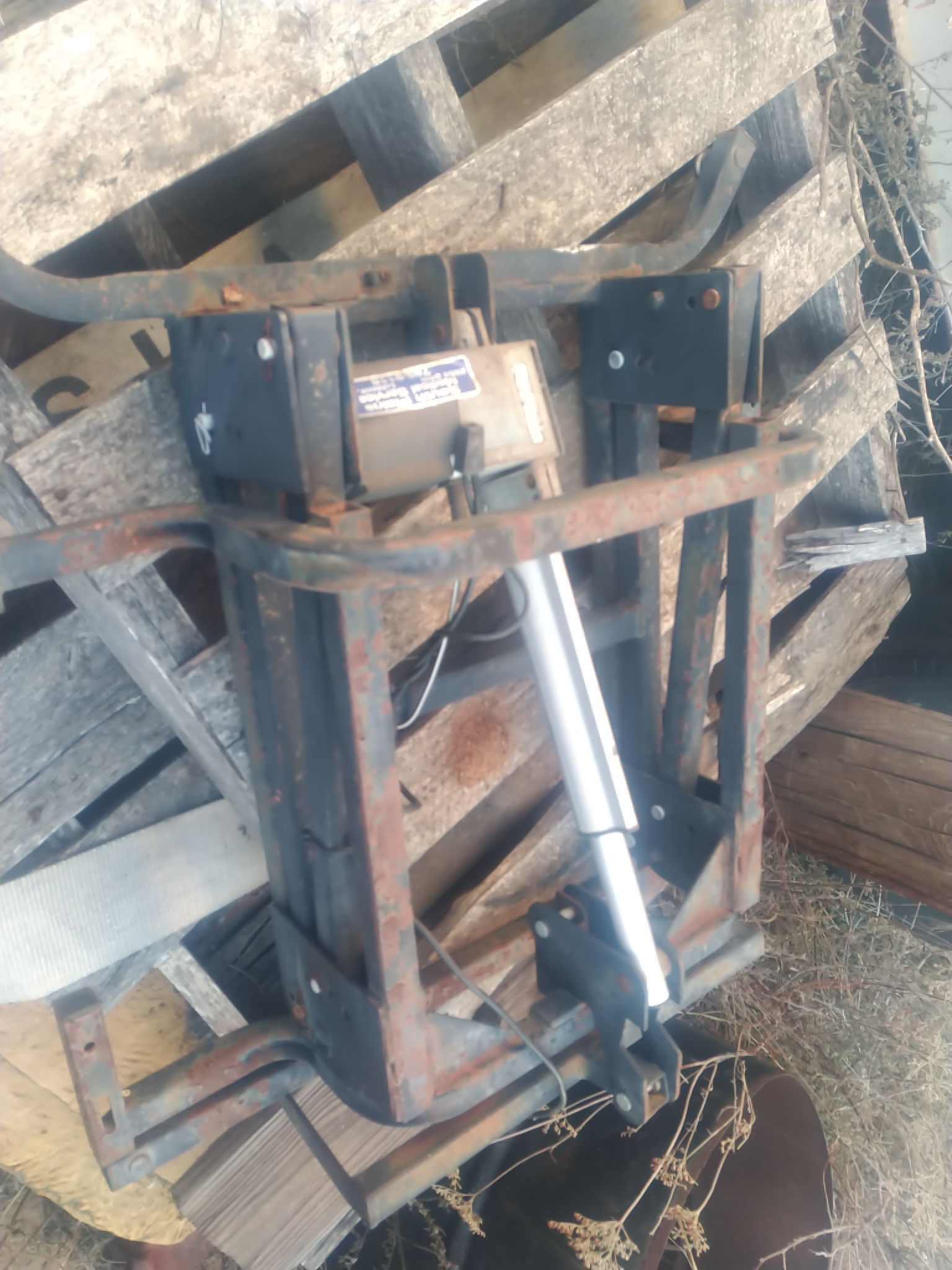
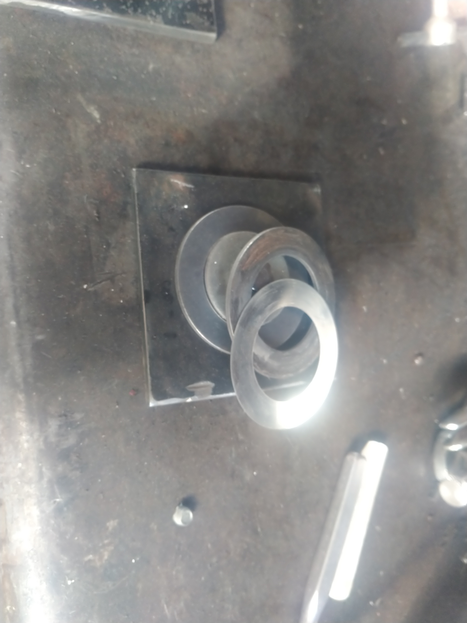
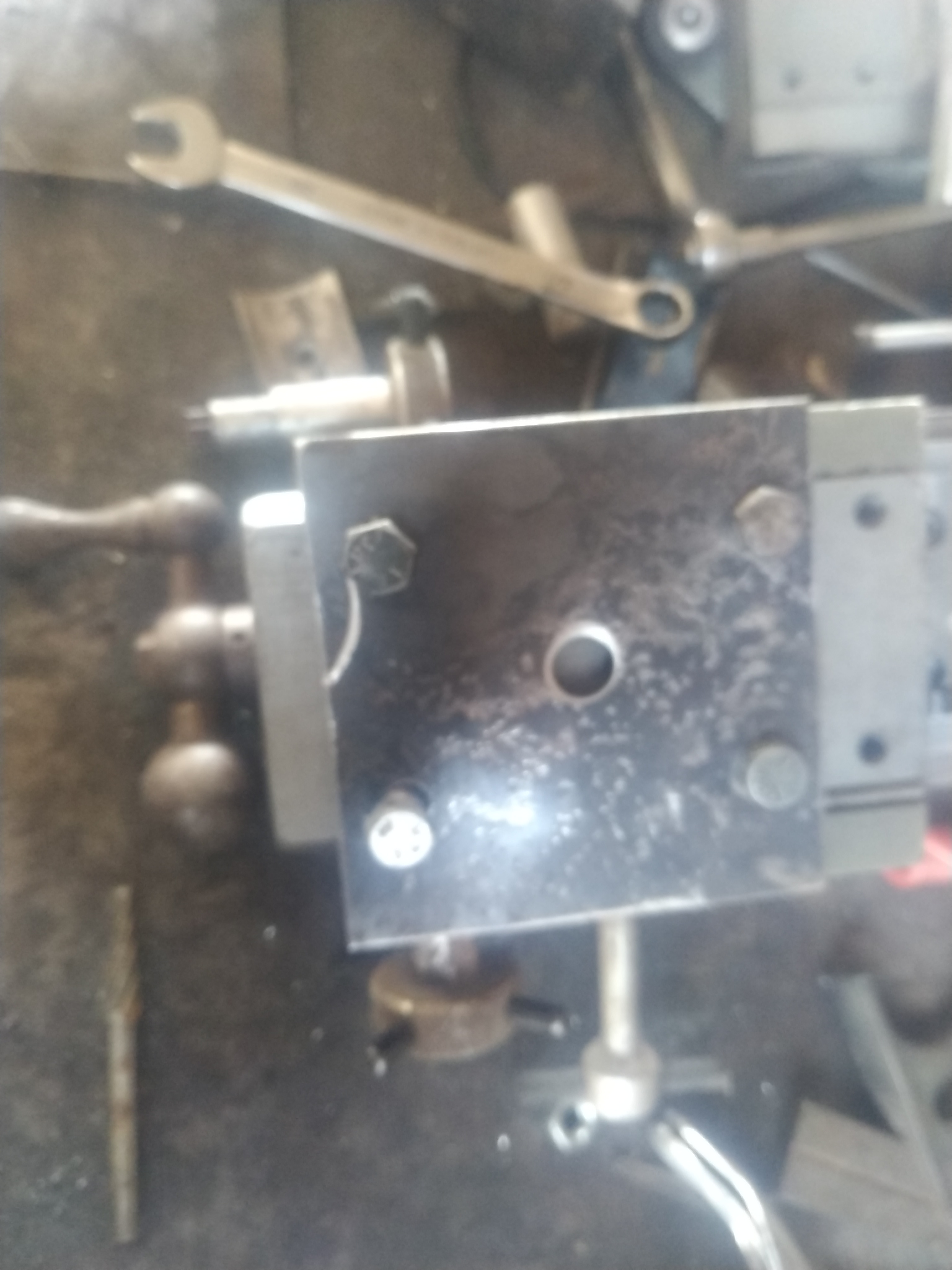
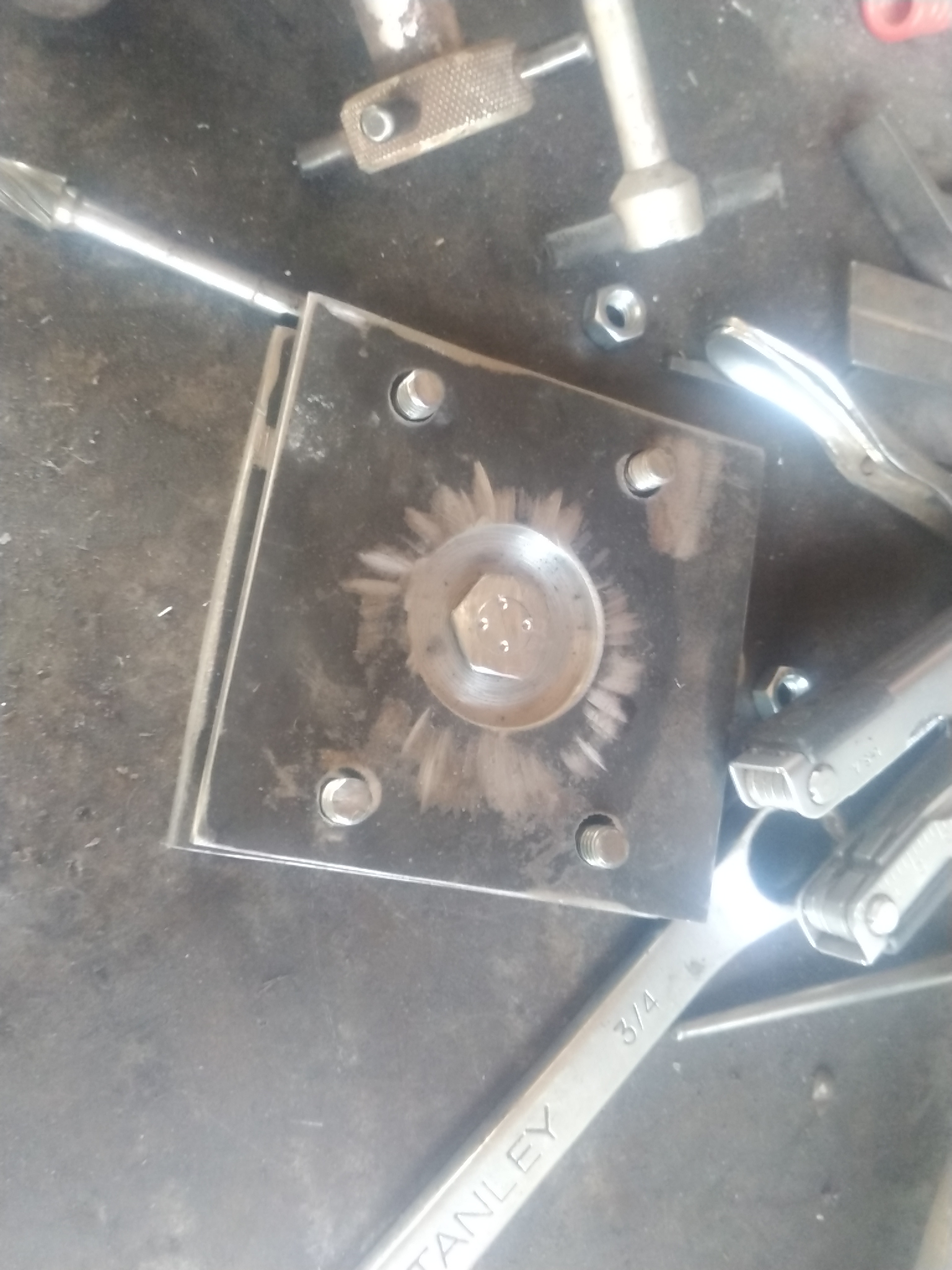
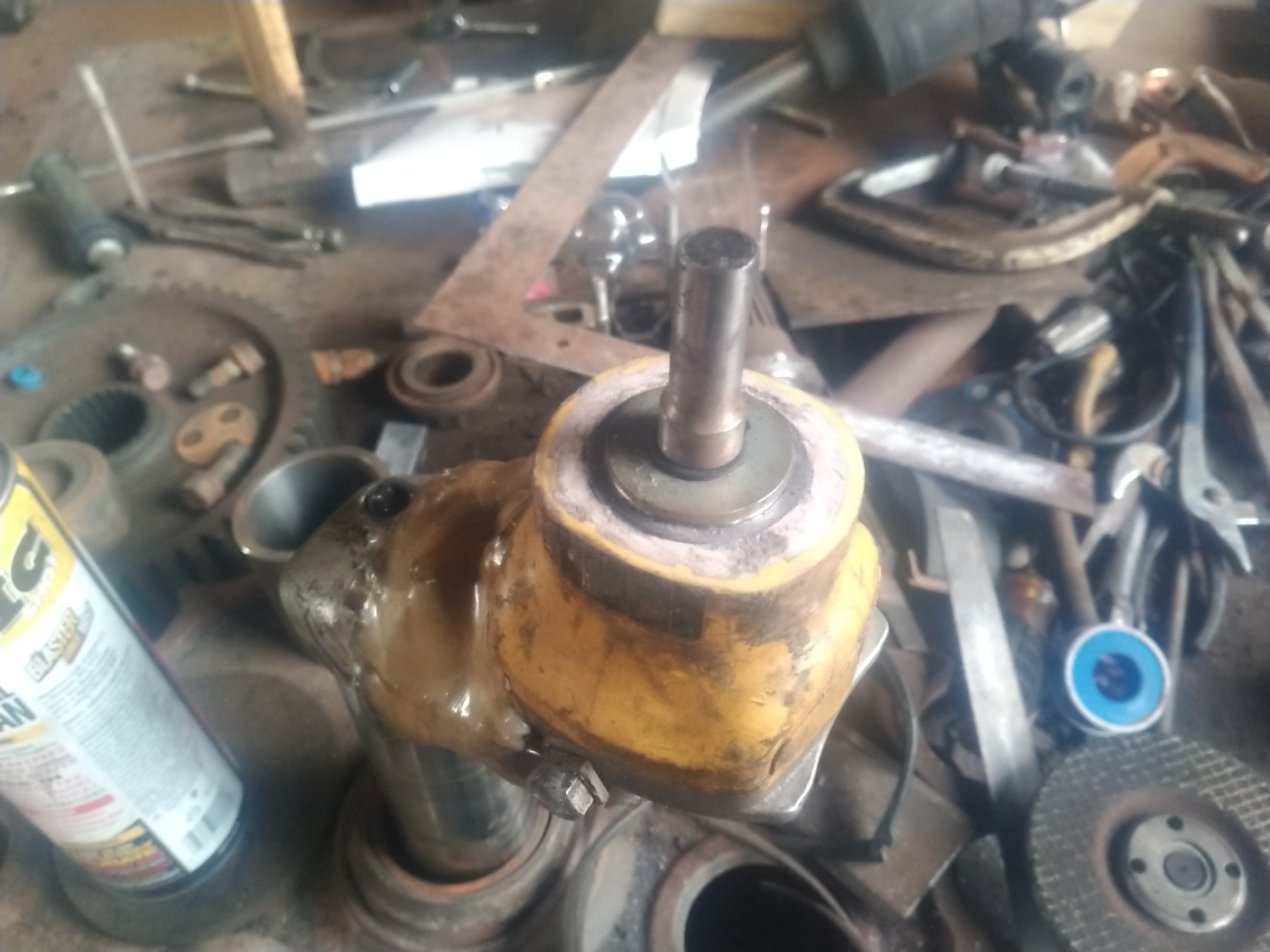
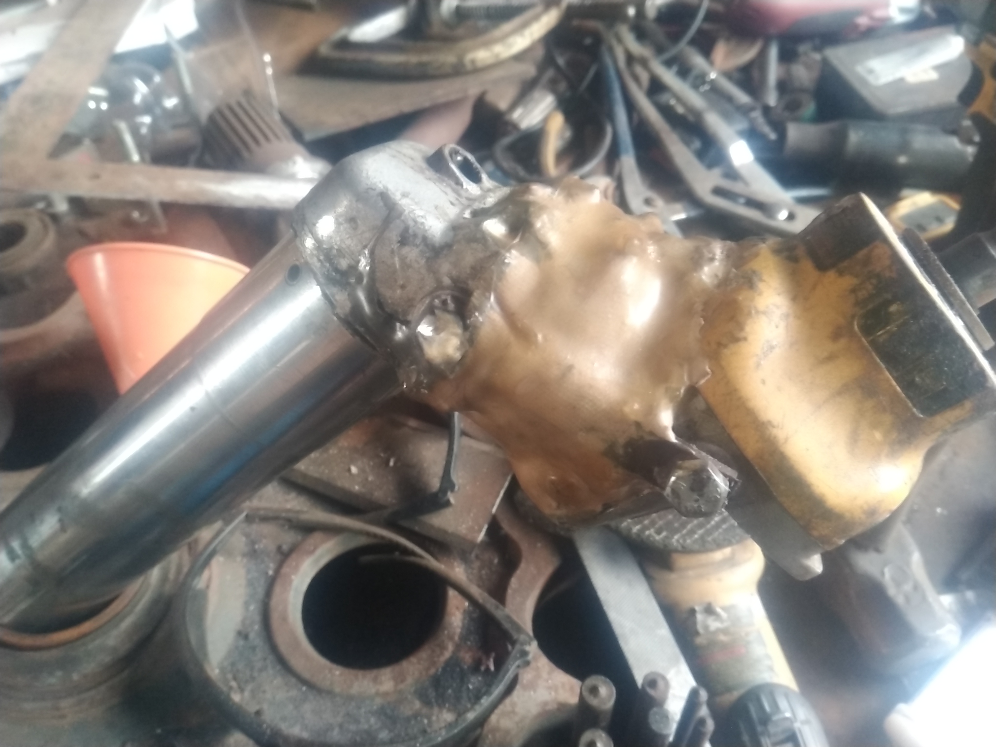
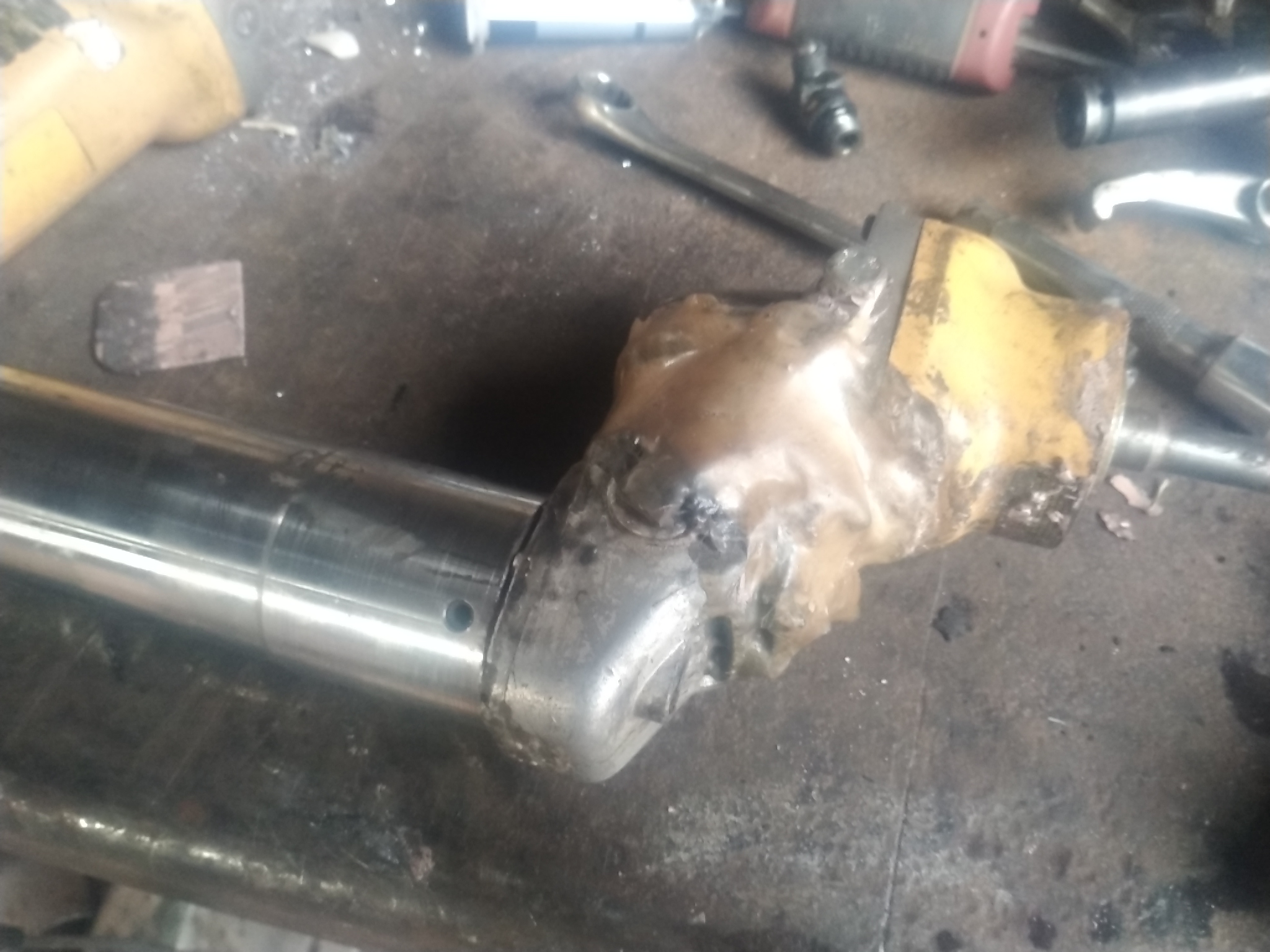
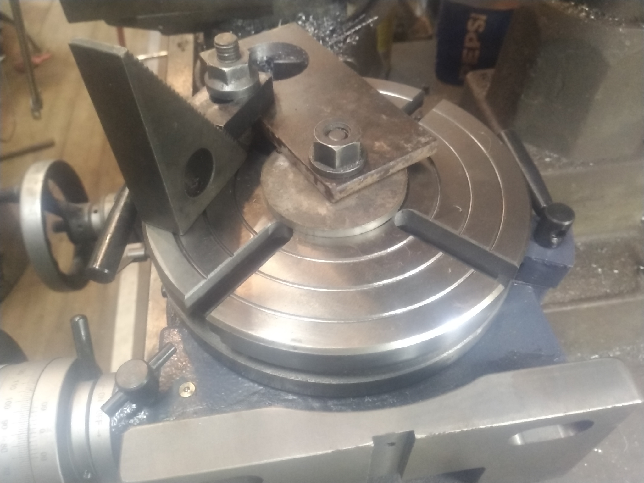
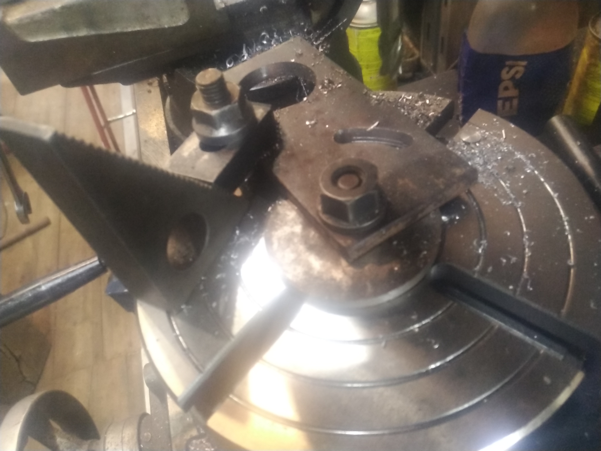
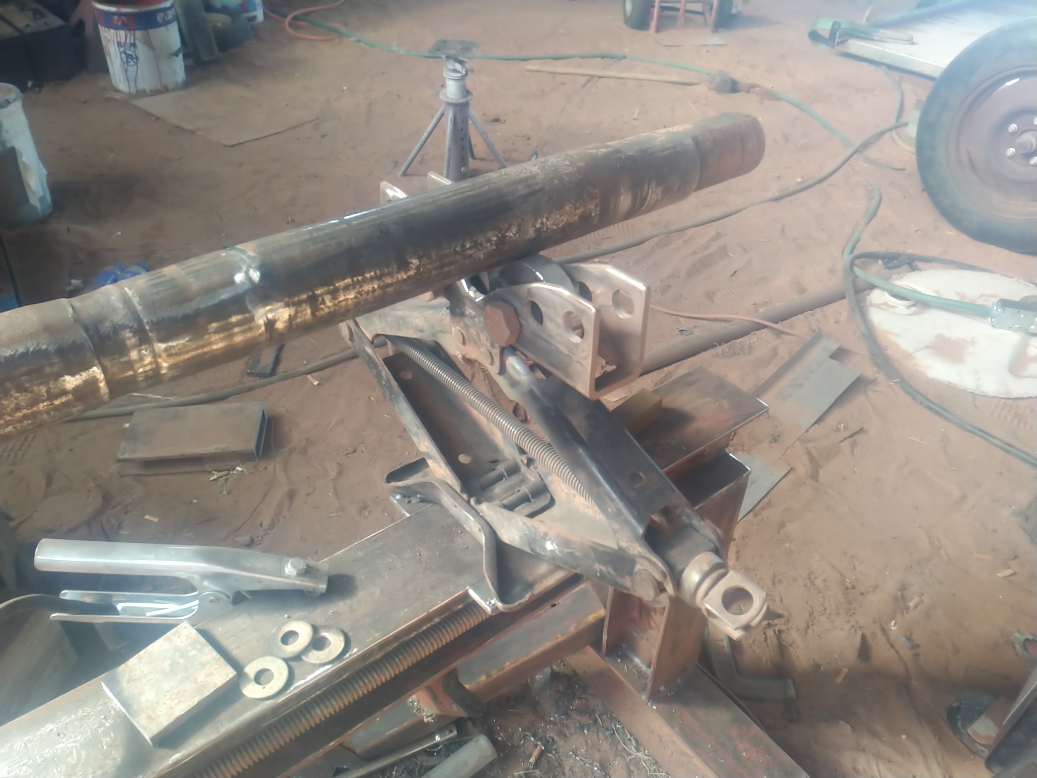
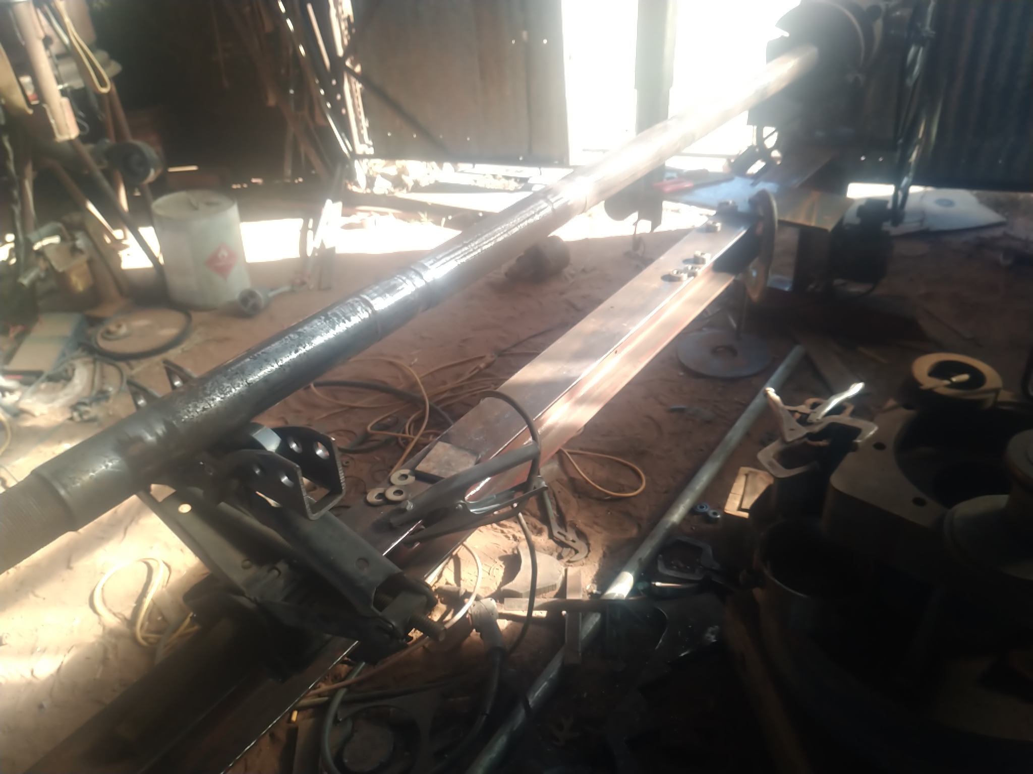
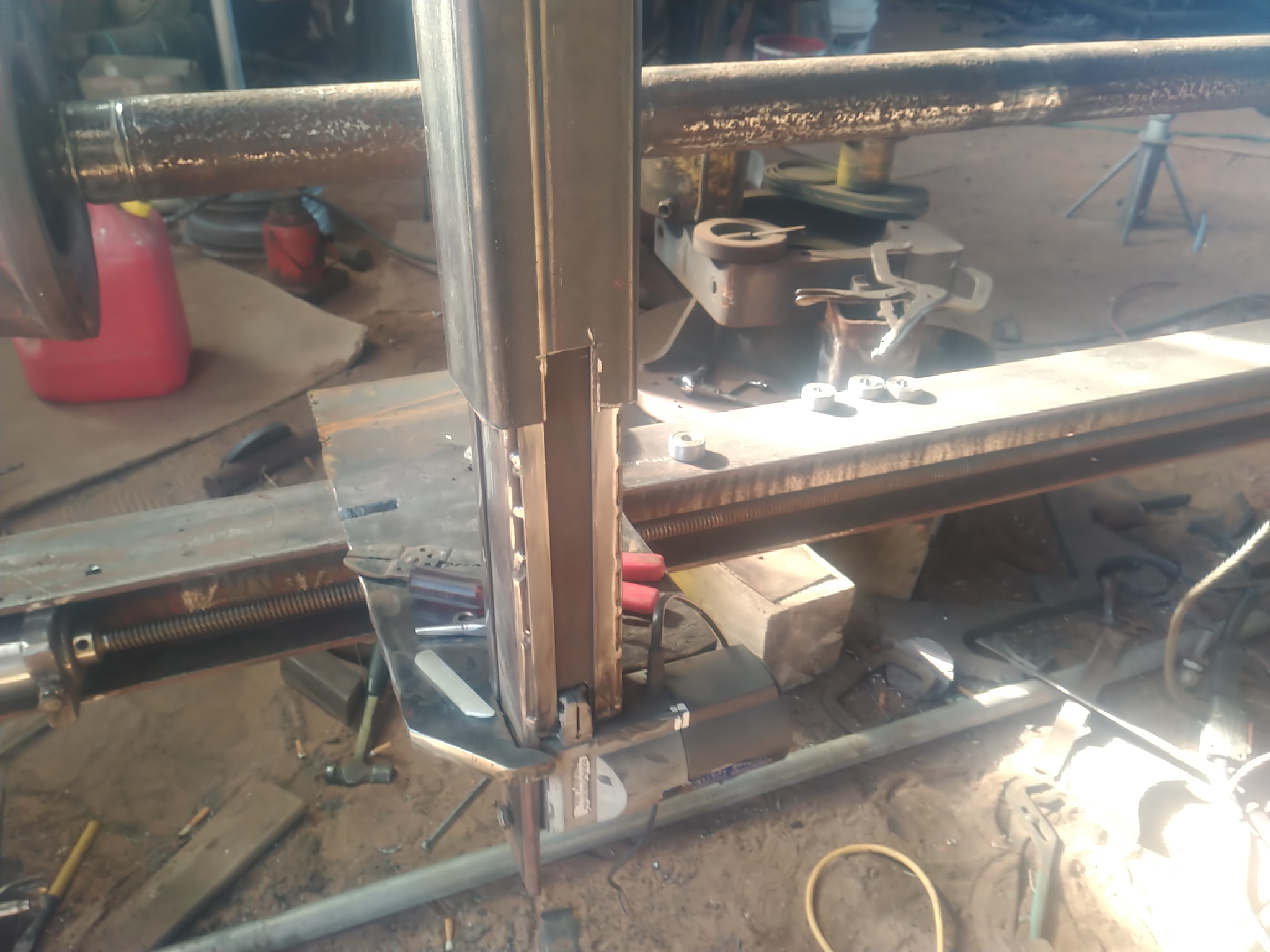
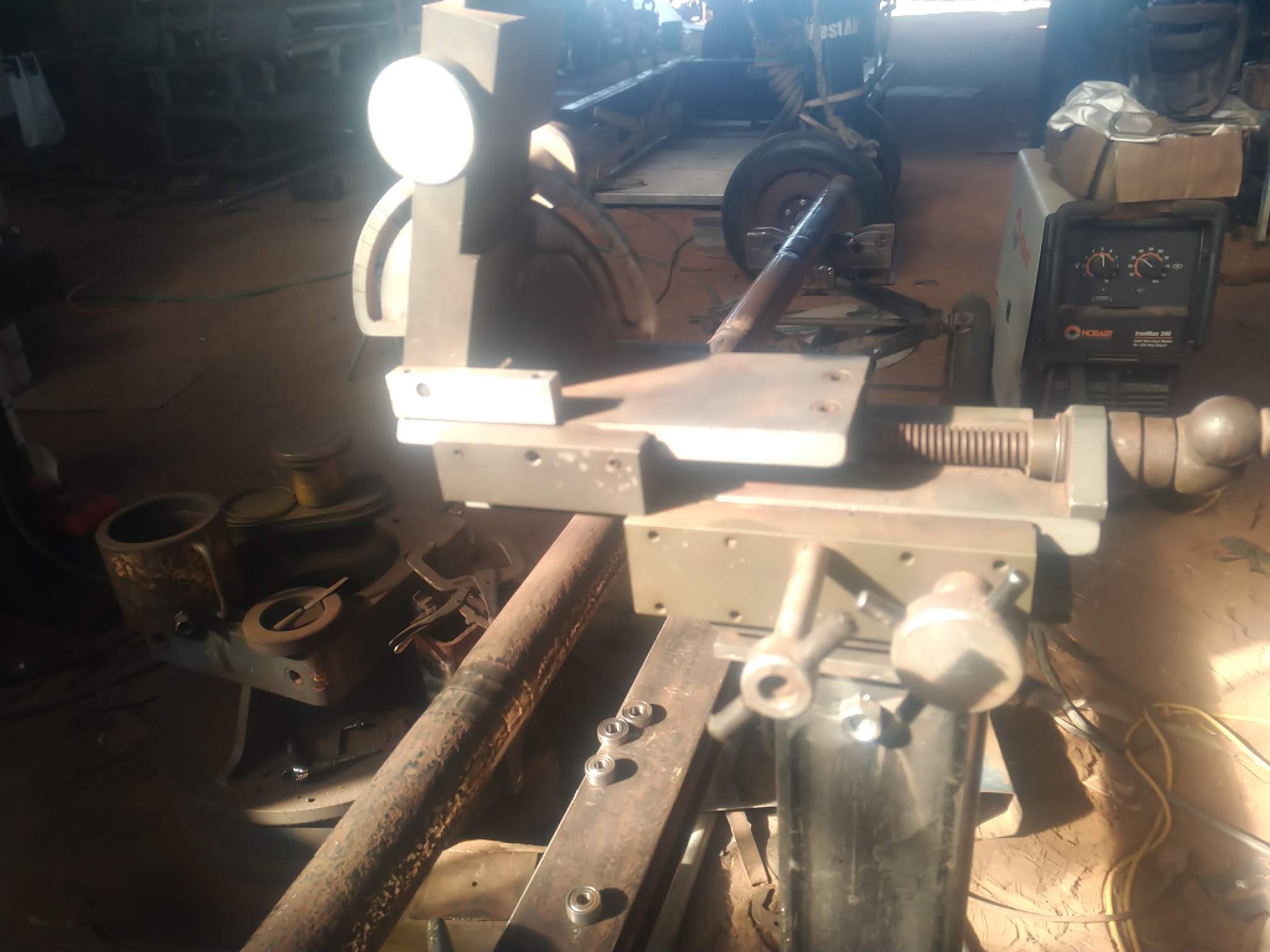
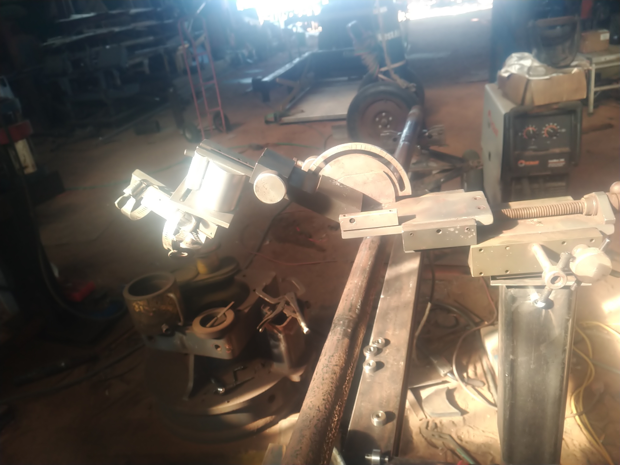
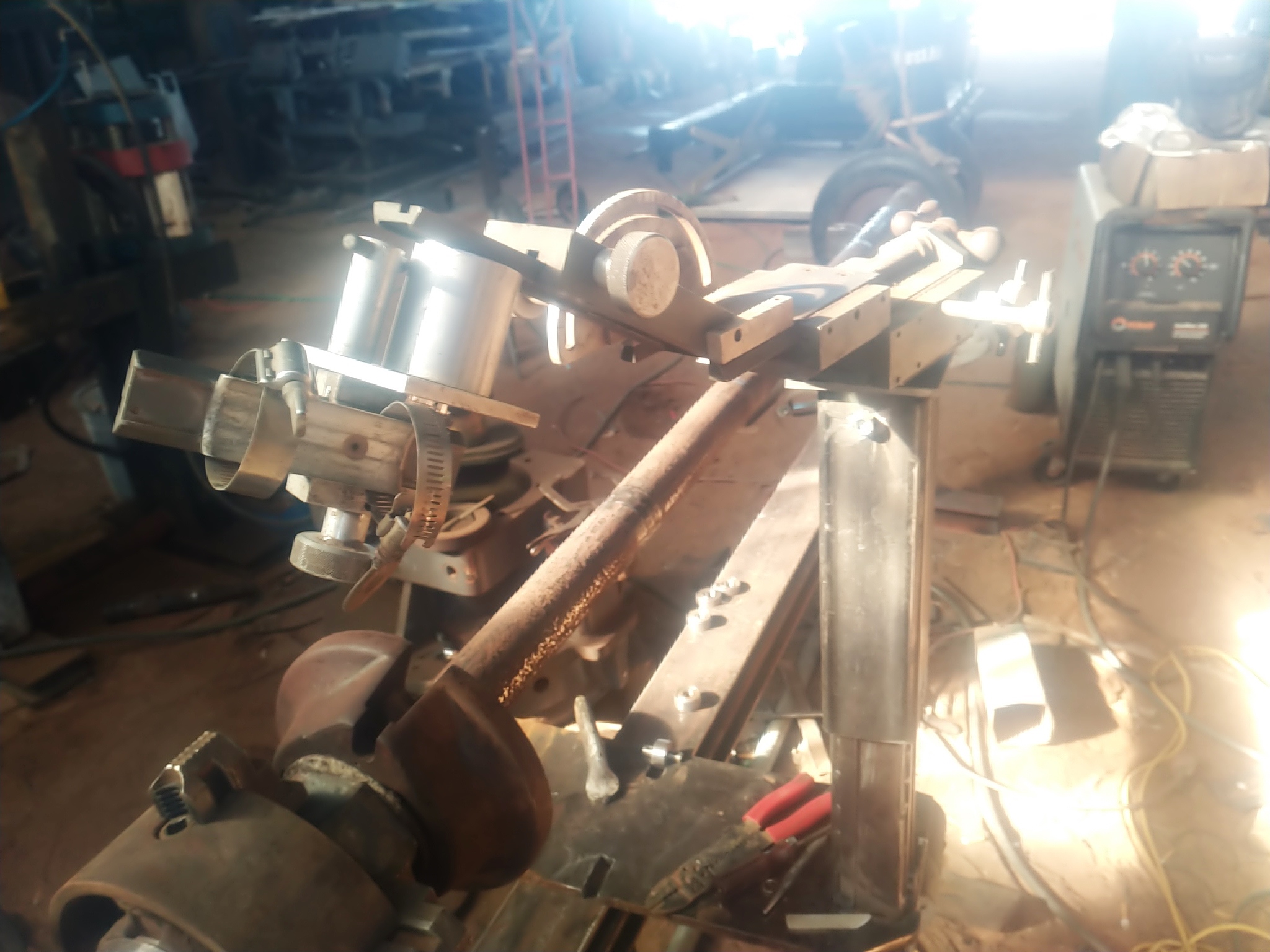
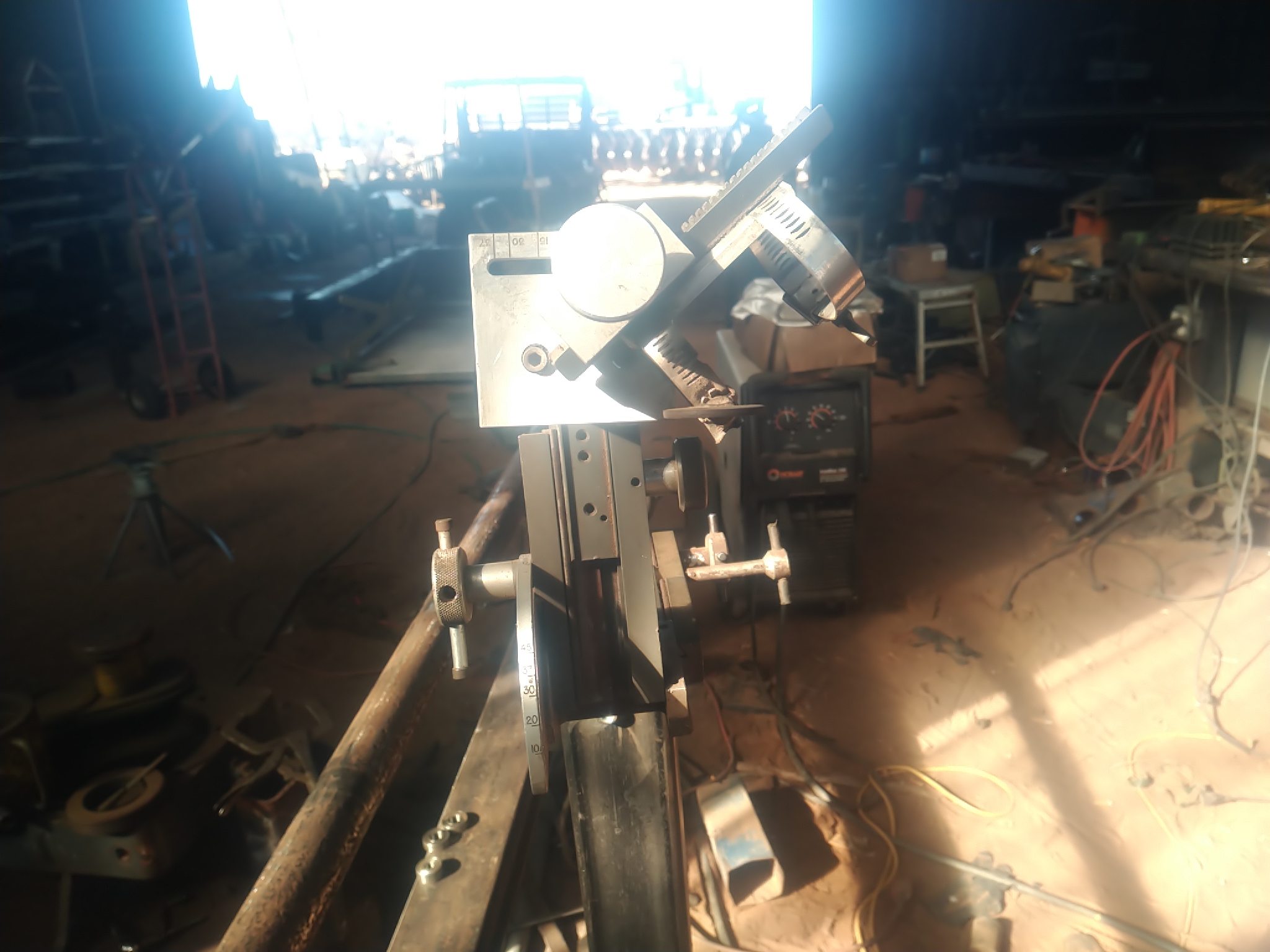
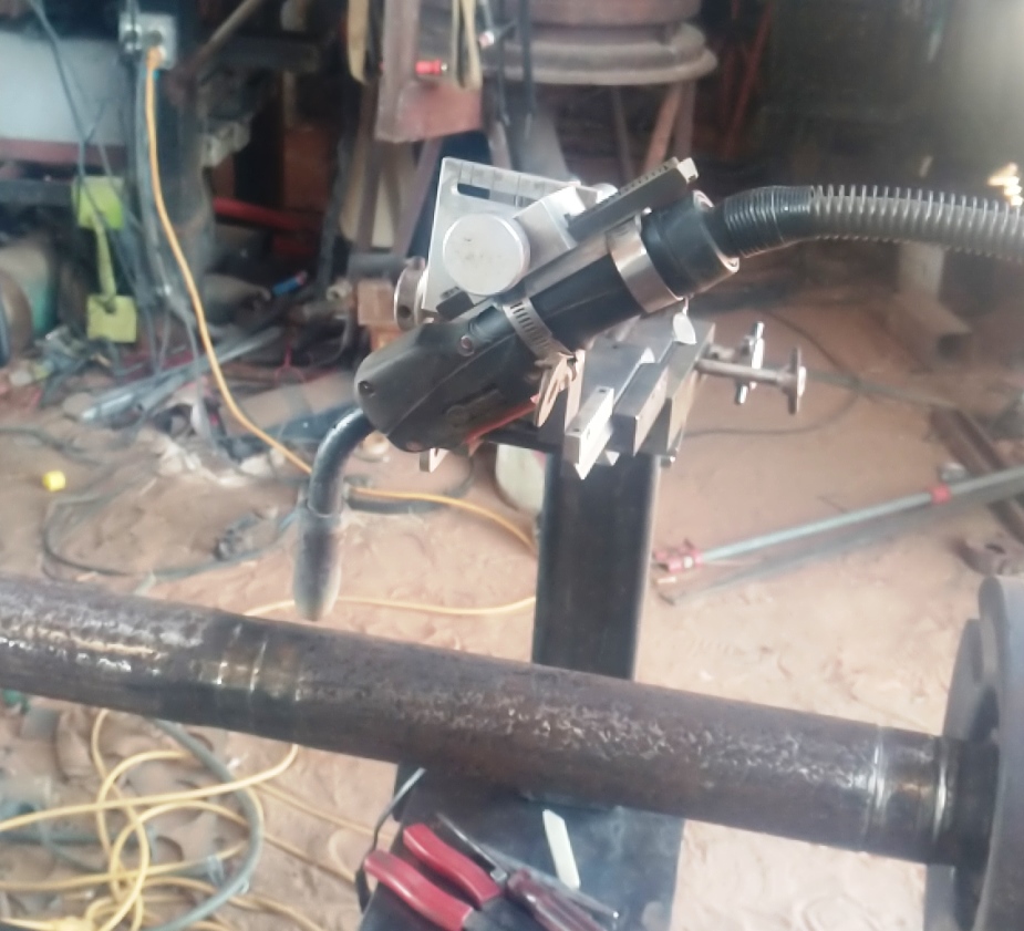
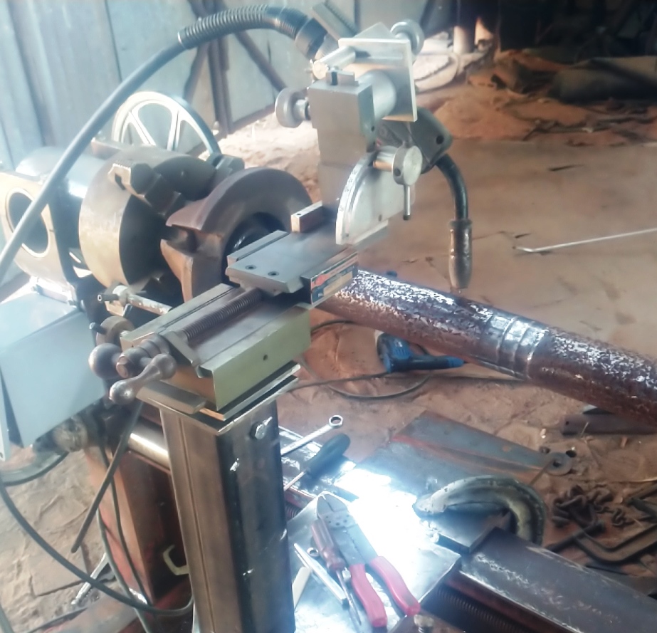
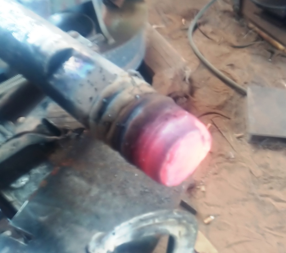
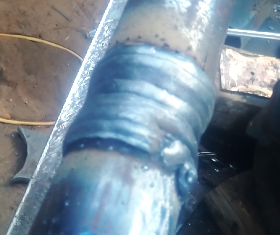
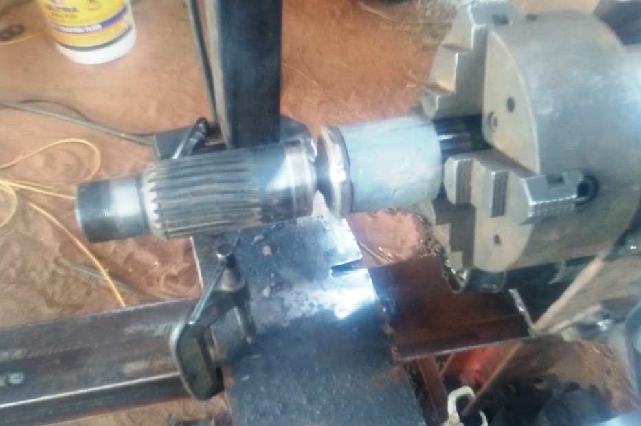
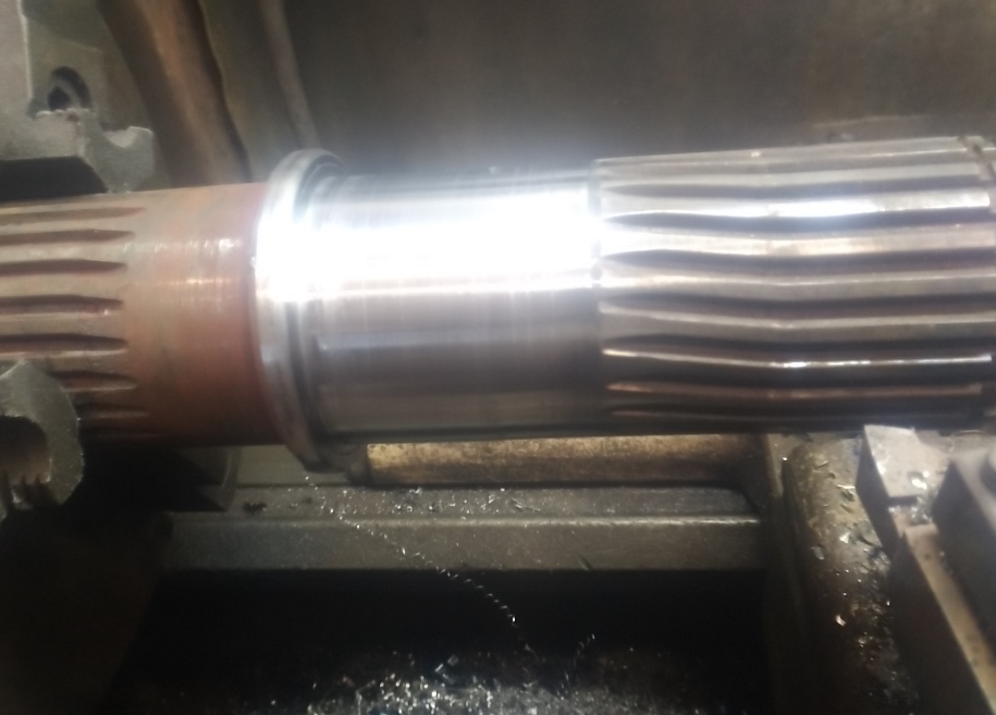
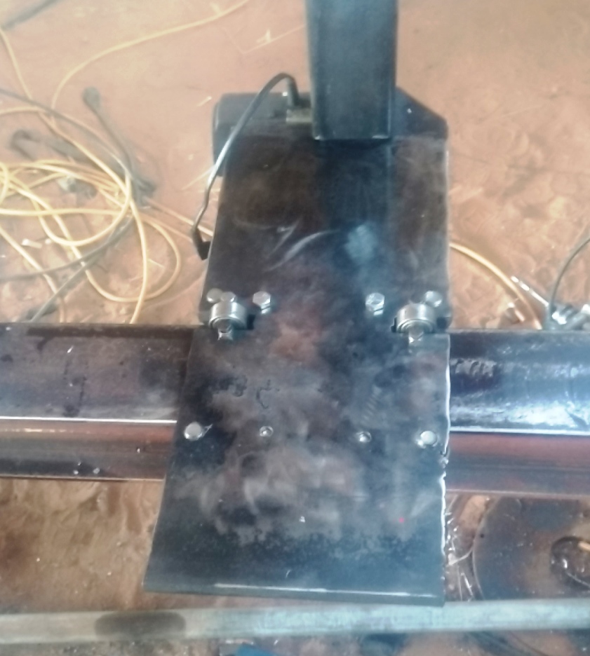
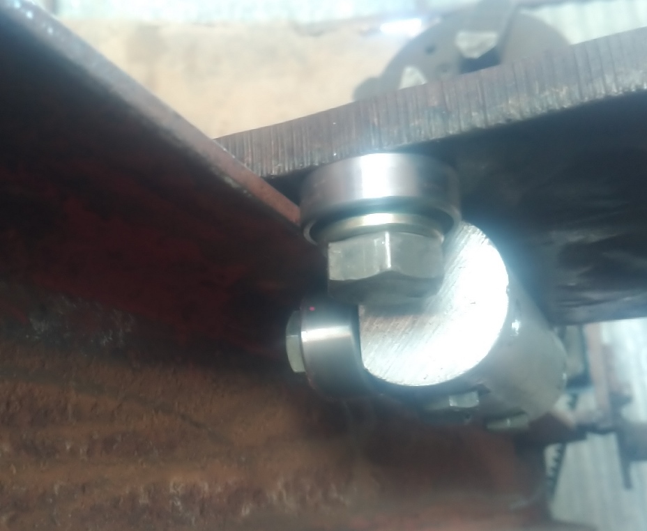
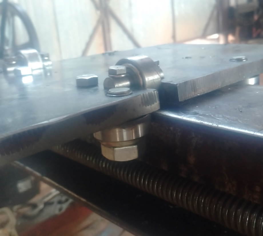
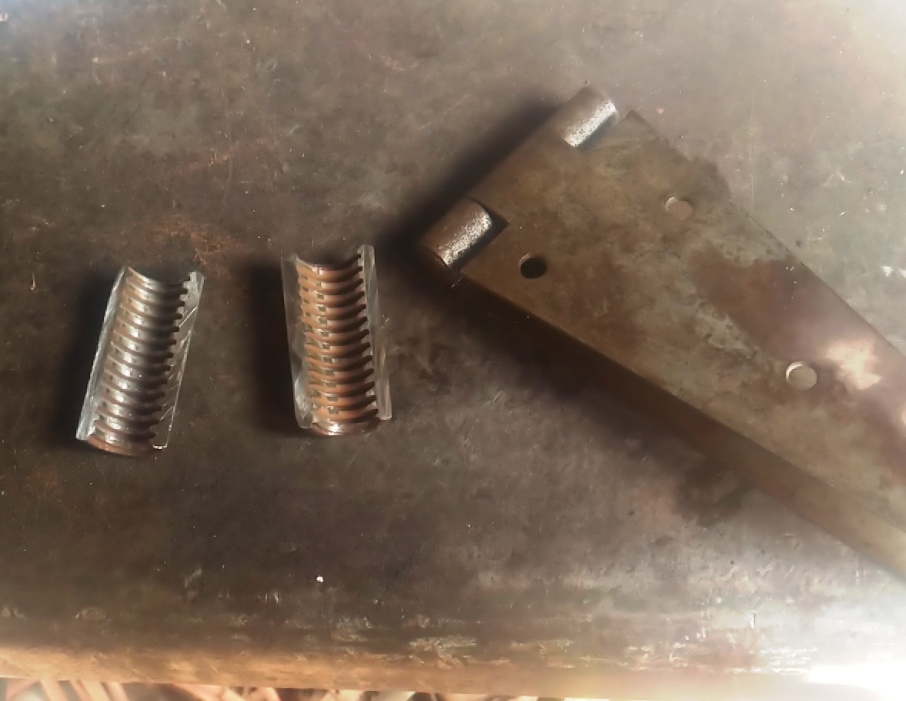
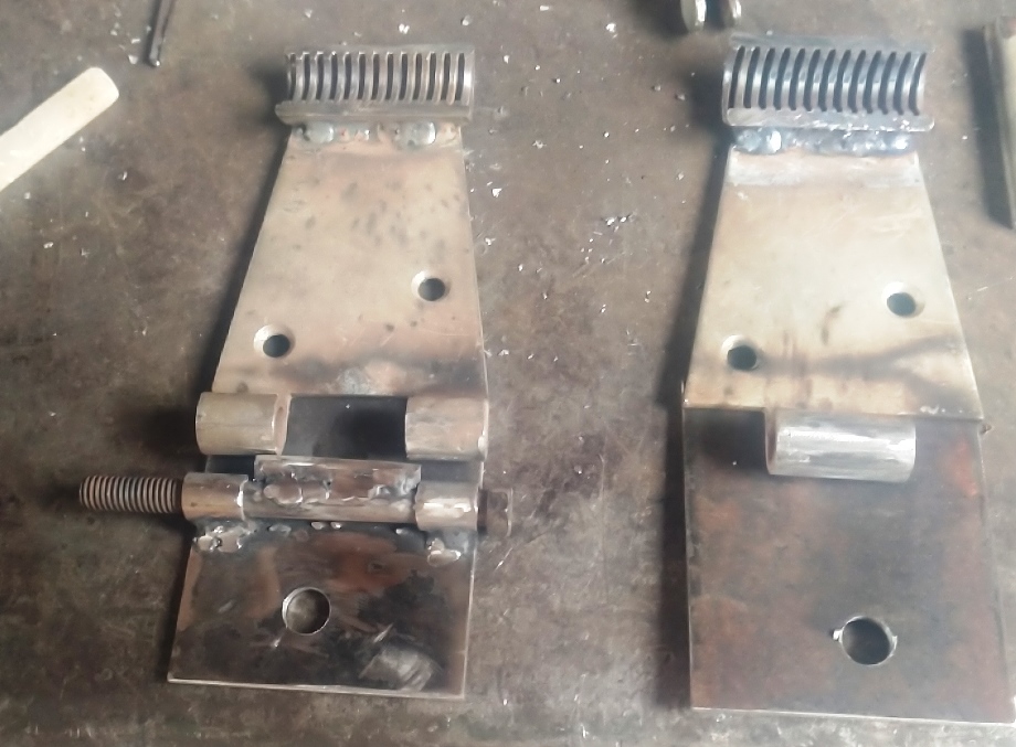
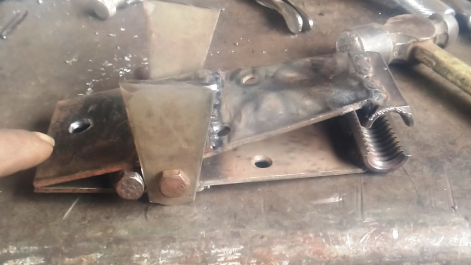
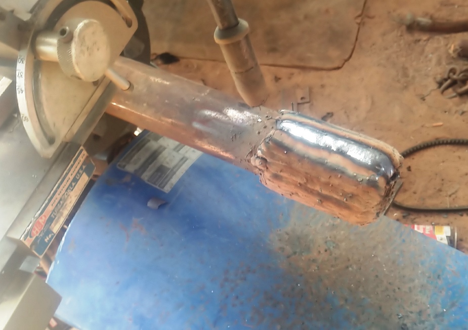
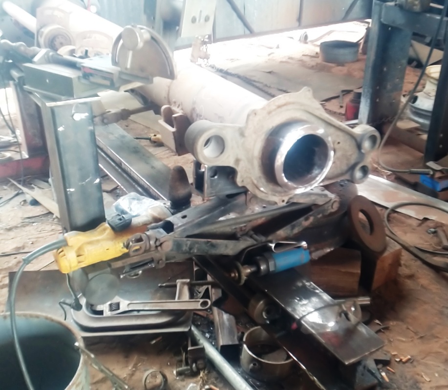
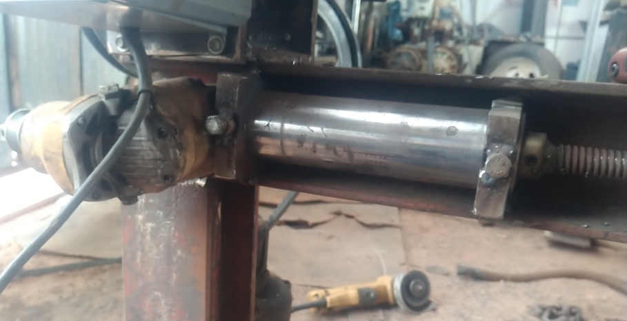
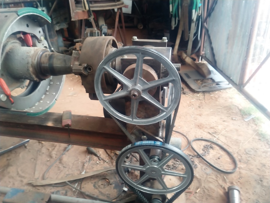
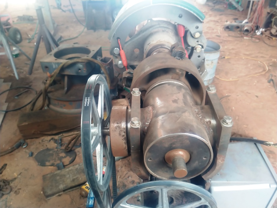
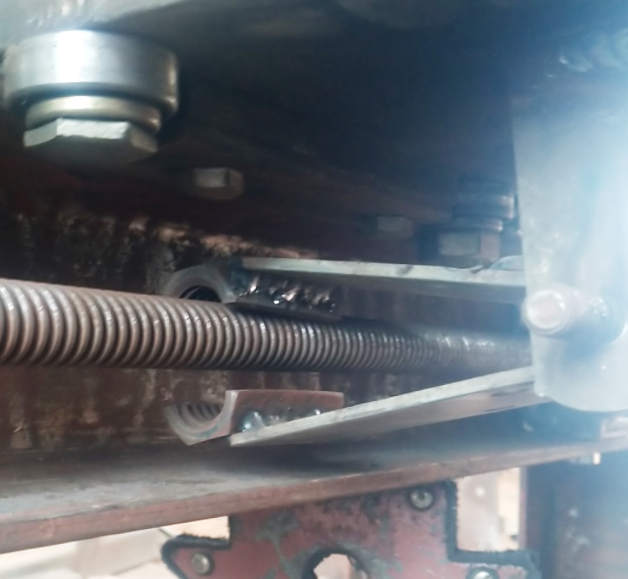
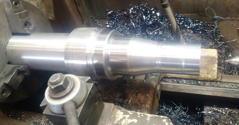
I made the headstock from scratch I wanted the main shaft to protrude out the rear to have a place for my ground clamp this meant I had to make it a right-angle gear box for the gears I used a spider gear and axle drive gear from the differential out of a Kenworth The housing is a length of 6" pipe split and spread then a piece welded in to make it large enough to house the gear and the bearings both ends are threaded to 20 TPI internal threads for the end caps and the oil seals I pressed the splines into the shaft for the drive gear to turn. The chuck backing plate and shaft are threaded to 1 3/4-12 TPI and locked in place with a grub screw between the threads from the end. To be able to make the head stock rotate from the horizontal position to vertical and anywhere in between I made it trunnion mounted the input shaft drives the smaller spider gear and has 2 bearings and a seal. the input side of the trunnion has a 12 TPI external thread for the end cap the saddle mounting clamps can be loosened or tightened to position the headstock at any angle between horizontal and vertical and there are adjustable stops preset at those positions. The main drive motor is from a 1960s era 450-amp Miller welder not sure what the gear reduction in it is. Moving to the drive for the 3/4-10 lead screw I started with a gear reduction drive motor from a 1980s era Miller 300-amp machine then I married the gear heads of 2 Dewalt 4 1/2" angle grinders to give me some offset for my lead screw drive In retrospect I probably could have done without them as the total reduction of the 2 ,ade the lead screw too slow for some operations like making long straight welds when the work piece was not being rotated. but not bad for rotational welding Just something I might change later maybe go to a CVT gear change system to either speed up or slow down beyond what the speed controllers can compensate for. I made the half nut out of an acme coupling nut that fits the 3/4-10 Acme lead screw and an old barn hinge with a couple of springs to hold it open the half nut is closed via a cam and lever. the Tail stock was made from a scissors jack with cross drilled platres so if need be, I can locate the rollers in different positions for larger or smaller diameter work pieces.
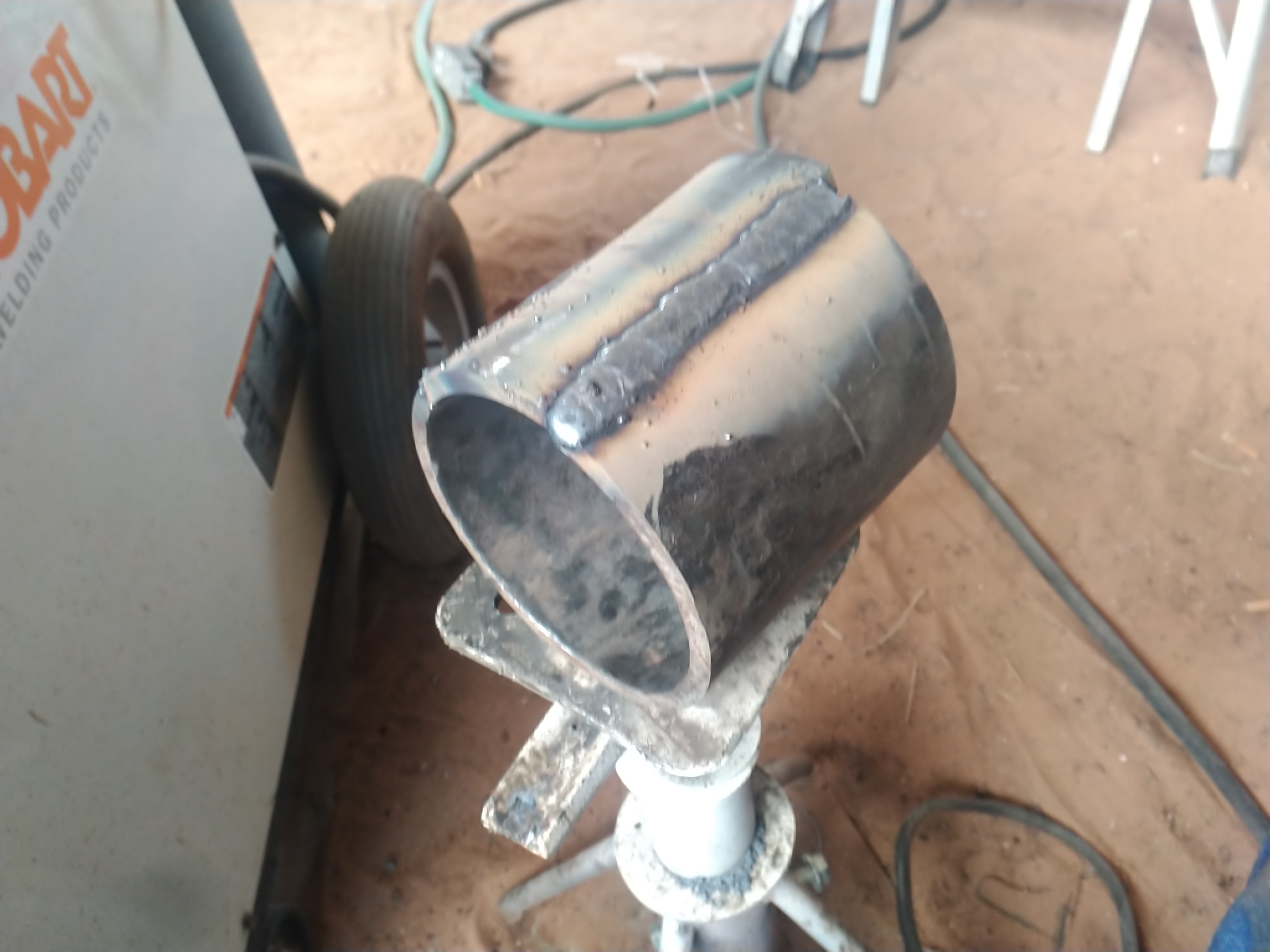
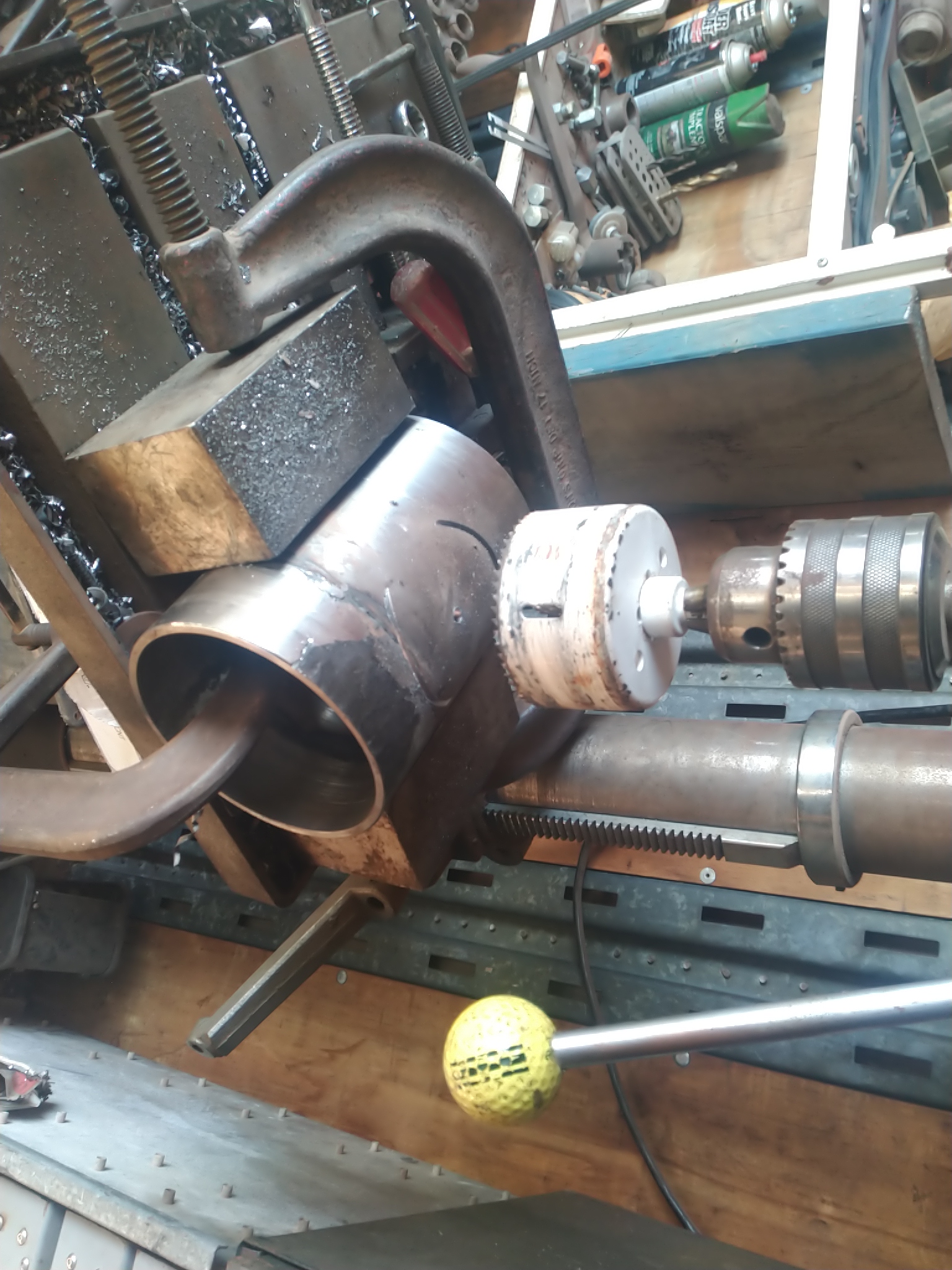
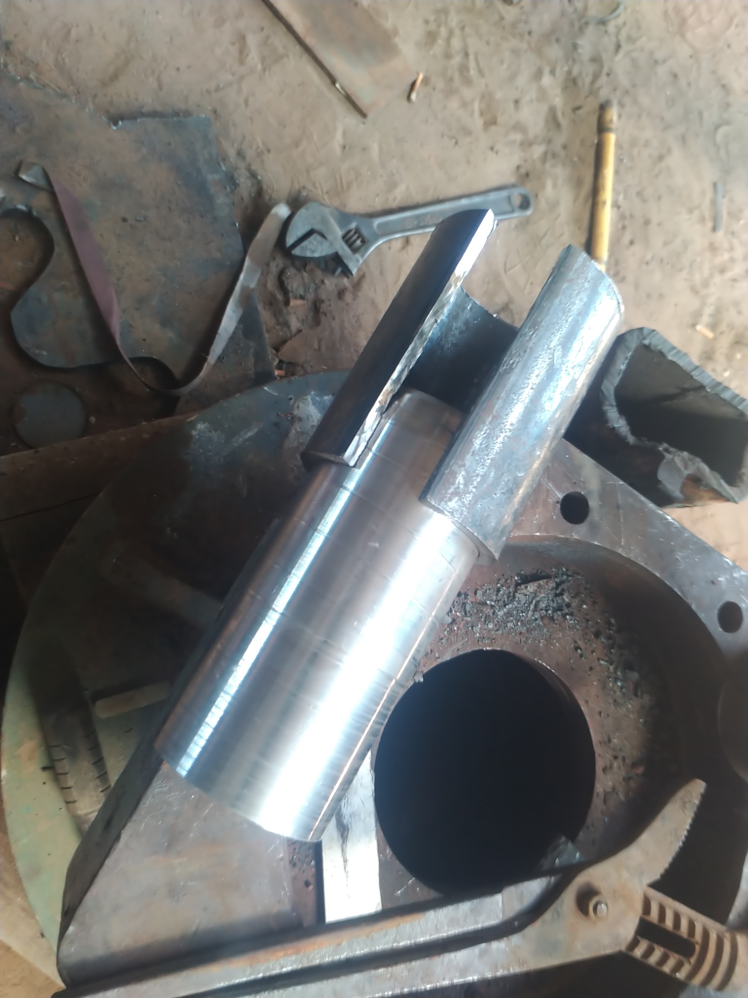
It may take several posts to show the whole build process and some of the projects


 Reply With Quote
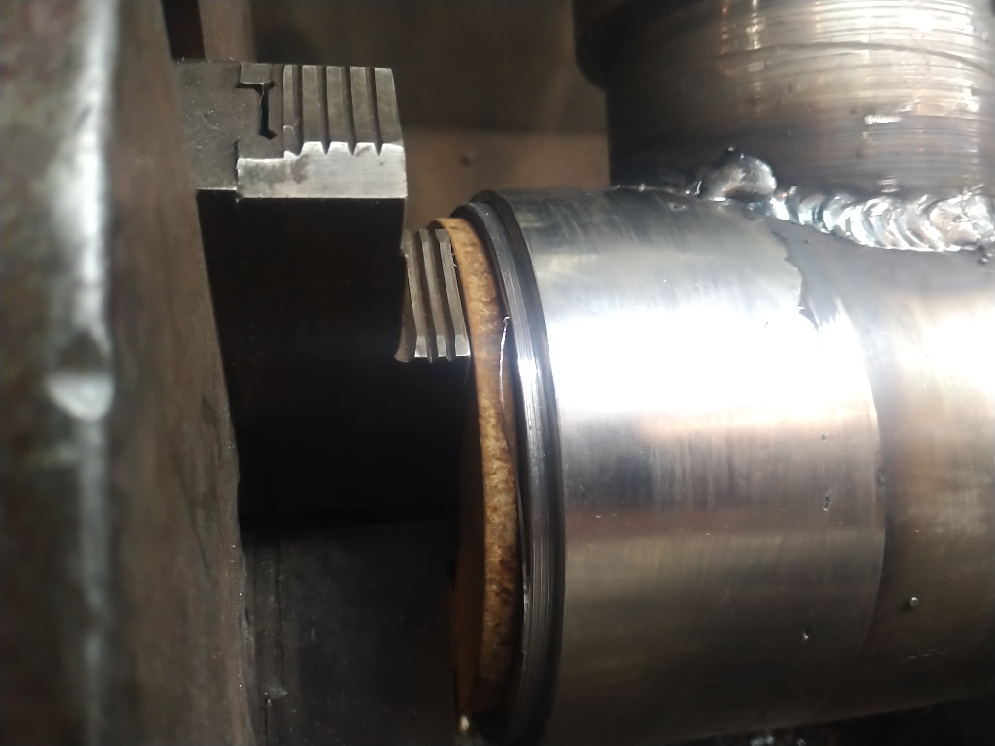


Bookmarks