Free 186 More Best Homemade Tools eBook:  
Get 2,000+ tool plans, full site access, and more.

User Tag List

Page 2 of 3 FirstFirst 1 2 3 LastLast
Results 11 to 20 of 26

Thread: Why crowned pulleys and bandsaw wheels?

  1. #11
    Supporting Member tonyfoale's Avatar
    Join Date
    Nov 2016
    Location
    Spain
    Posts
    1,566
    Thanks
    690
    Thanked 2,648 Times in 709 Posts

    tonyfoale's Tools
    Dan,

    I have only just seen your message. I haven't yet figured out how to keep track of comments on my posts yet. This is the only forum that I am active on, so there is still much to learn.
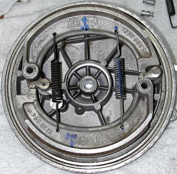
    I know that many people do as you have, that is machine the shoes a little undersize. The problem with that approach is that the shoes don't have the same curvature as the drum until they have worn a bit. That contributes to spunginess.
    What I do is, shim the shoes out from the cams and then machine the shoes to drum size. Then with the shims removed the backplate/shoe assembly will fit and when the brake is applied the shoes and drum will match. I use an expanding mandrel to hold the back plate when machining the shoes to ensure concentricity.
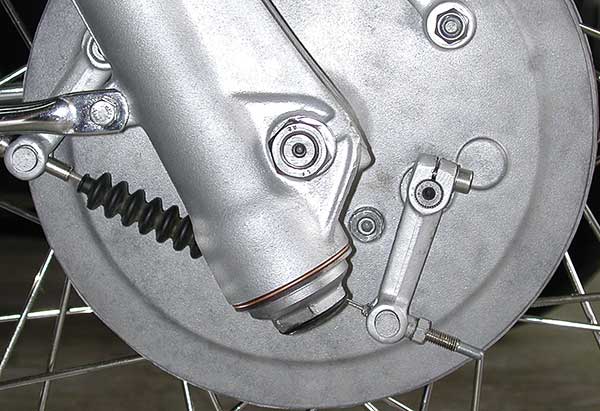
    Another thing that I do differently from the norm is to do with the cam lever actuation. The norm is to have a rigid adjustable rod between the two levers as you have done. Getting that adjustment spot on for equal pressure on each shoe is not easy and any error will cause spunginess also. I can't take credit for an alternative method because I first saw it on the Earles forked BMWs that I had in the 1960s. As soon as I saw it I saw how clever it was and it made perfect sense. You have the outer cable connected to one of the cam levers (instead of fixed to the backplate) and the inner cable to the other cam lever. Now the force on the two levers is balanced. This method demands that the cams are symmetrical, or else designed for the job, because it will be the outer edge of one cam that operates the shoe and the inner edge of the other cam. That lack of symmetry slightly changes the leverage on the shoe for a given torque on the external cam lever. That imbalance is not too important but can easily be fixed by making the two cam levers with slightly different lengths. IIRC BMW used equal length levers but I make the correction with different lengths.
    I hope that convoluted explanation makes sense. I'll try and dig up some sketches or photos. Otherwise Mr Google may know about it.

    PS. The full cable force is applied to each cam lever, whereas the rigid rod system has to share the application force between the two. So for equal lever lengths on the two systems, the rigid rod system will brake less for a given cable force. However, there are two sides to leverage - force and displacement. Although the cable only system produces more force on the cam levers it does this at the expense of double overall cable movement, so it will feel more powerful but also more spungy, the answer to this is to shorten the cam actuation levers to return to the original overall leverage.

    186 More Best Homemade Tools eBook

  2. The Following User Says Thank You to tonyfoale For This Useful Post:

    Toolmaker51 (Jan 4, 2017)

  3. #12
    Supporting Member tonyfoale's Avatar
    Join Date
    Nov 2016
    Location
    Spain
    Posts
    1,566
    Thanks
    690
    Thanked 2,648 Times in 709 Posts

    tonyfoale's Tools
    I accidentally posted this in the clutch rectification post in the first place. Time to correct my silly error.

    I found some pix of the BMW drum brake activation.

    Attachment 15784
    You can see the outer cable connected to the left side lever and the inner cable connected as usual to the inner cable

    Attachment 15785
    Here you can see the BMW solution, which I had forgotten, to the problem that I mentioned of slightly different leverage of the cam on each shoe. Basically they offset one of the cams from the usual position. to ensure that the cam contact point on each shoe was the same.
    There is some other cleverness in there also. With this cable on each lever system all the springs do is pull the shoes closer relative to each other so one shoe may be pulled away from the drum while the other is left rubbing. The solution adopted was to have one spring stronger than the other and have an adjustable shoe stop. So the stronger spring would pull one shoe onto the stop so it couldn't withdraw any more and then the other shoe would be pulled back until stopped by the cable adjustment in normal fashion. In my opinion all DLS brakes should be done that way.

    There is some free software on my web site about drum brakes which you might find of interest, it is freeware.

    2000 Tool Plans

  4. #13
    Supporting Member Moby Duck's Avatar
    Join Date
    Jan 2016
    Posts
    388
    Thanks
    1,222
    Thanked 197 Times in 124 Posts

    Moby Duck's Tools
    Quote Originally Posted by tonyfoale View Post
    Gyroscopic effects are my favourite example of that. Pick up a physics book and it is bound to have a mathematical derivation of the standard relationship between torque and spin velocities. However, even most engineers and scientists that I have discussed this with don't have a good grasp of the relationship of the simple maths to the seemingly magic reactions you get when playing with bicycle wheels. I have developed a straightforward explanation of this and those who have seen it light up like a light bulb. They finally make the connection. It is equally enlightening to those with and without the maths understanding.
    I have spent many years working with and repairing Gyros, and I understand the theory of how they work but I am often asked "how do they work" and it is very difficult to explain this to those without the basics. I would be very interested to read your straightforward explanation so that I can explain it better. I hate the blank looks I often get when I try to explain it all. Of course the new Piezo, LED, Laser "Gyros" so common today, have stolen the real Gyro's name and work differently.

  5. #14
    Supporting Member Moby Duck's Avatar
    Join Date
    Jan 2016
    Posts
    388
    Thanks
    1,222
    Thanked 197 Times in 124 Posts

    Moby Duck's Tools
    Great explanation on why pulleys need to be crowned, I understand at last.
    Now can you tell me which wheels on a 2" x 72" Belt Grinder with 4 wheels, (2 on the platen, 1 for tracking, and 1 being the driven wheel),need to be crowned. There is much debate on this on the web. Some say all 4 wheels, some say just the tracking wheel, some say just the driven wheel and some say both the driven and tracking wheels need to be crowned.

  6. #15
    Supporting Member tonyfoale's Avatar
    Join Date
    Nov 2016
    Location
    Spain
    Posts
    1,566
    Thanks
    690
    Thanked 2,648 Times in 709 Posts

    tonyfoale's Tools
    Quote Originally Posted by Moby Duck View Post
    Great explanation on why pulleys need to be crowned, I understand at last.
    Now can you tell me which wheels on a 2" x 72" Belt Grinder with 4 wheels, (2 on the platen, 1 for tracking, and 1 being the driven wheel),need to be crowned. There is much debate on this on the web. Some say all 4 wheels, some say just the tracking wheel, some say just the driven wheel and some say both the driven and tracking wheels need to be crowned.
    There is always some misalignment between pulleys due to manufacturing tolerances etc, so if you crown them all then each will be trying to align the belt on itself. So you'll end up with the effects from each pulley fighting the effects from the others, thereby putting some unwanted and unnecessary stress in the belt.
    If you only crown one then that one will align the belt which will then find its own position on the other pulleys provided that they are wide enough. Of course with a tiltable tracking wheel you can adjust the belt centrally over the other pulleys.
    So which wheel track with? I think that the answer now becomes clear, it is unlikely to be a good idea to use a crown wheel to align the belt and other to then realign it elsewhere.
    So it's one crowned pulley which has the tracking control.

    Strange that this topic came up yesterday, because then I pulled that little Burgess saw apart (which features at the beginning of this topic) to give it a 50 year service. The drive belt which the blade runs on is badly chewed up and the top pulley has seen better days. 2 new belts should arrive today, they should see me OK good for the next 100 years. The wheels are made of a hard plastic with no rubber tyres so I shall machine the rims smooth again and glue on some tyres cut from an inner tube. I'll only be crowning the top wheel.

  7. The Following User Says Thank You to tonyfoale For This Useful Post:

    Moby Duck (Jan 12, 2018)

  8. #16
    Supporting Member tonyfoale's Avatar
    Join Date
    Nov 2016
    Location
    Spain
    Posts
    1,566
    Thanks
    690
    Thanked 2,648 Times in 709 Posts

    tonyfoale's Tools
    Quote Originally Posted by Moby Duck View Post
    I have spent many years working with and repairing Gyros, and I understand the theory of how they work but I am often asked "how do they work" and it is very difficult to explain this to those without the basics. I would be very interested to read your straightforward explanation so that I can explain it better. I hate the blank looks I often get when I try to explain it all. Of course the new Piezo, LED, Laser "Gyros" so common today, have stolen the real Gyro's name and work differently.
    OK, I'll made that a separate post though, so watch out for it.

    I agree about the name gyro being hijacked by totally different devices. When the Segway came out the press reports stated that it was gyro stabilised. As you will know it would have had to be bigger and heavier to do that. In reality it used an IMU, inertia sensors, to detect its balance state and then apply torque to the wheels to correct balance errors. No gyros in sight.

  9. The Following User Says Thank You to tonyfoale For This Useful Post:

    Moby Duck (Jan 12, 2018)

  10. #17
    Supporting Member Moby Duck's Avatar
    Join Date
    Jan 2016
    Posts
    388
    Thanks
    1,222
    Thanked 197 Times in 124 Posts

    Moby Duck's Tools
    Thanks, you have confirmed what I already believed about the best wheel to crown but I needed your opinion to be sure.

    I shall watch for the Gyro post.

  11. #18
    Supporting Member tonyfoale's Avatar
    Join Date
    Nov 2016
    Location
    Spain
    Posts
    1,566
    Thanks
    690
    Thanked 2,648 Times in 709 Posts

    tonyfoale's Tools
    Quote Originally Posted by Moby Duck View Post
    Thanks, you have confirmed what I already believed about the best wheel to crown but I needed your opinion to be sure.

    I shall watch for the Gyro post.
    The gyro explanation has been posted here http://www.homemadetools.net/forum/g...ut-maths-65745

  12. The Following User Says Thank You to tonyfoale For This Useful Post:

    Moby Duck (Jan 14, 2018)

  13. #19
    Supporting Member metric_taper's Avatar
    Join Date
    Mar 2017
    Location
    Marion, Iowa
    Posts
    586
    Thanks
    228
    Thanked 257 Times in 153 Posts

    metric_taper's Tools
    Tony Foale: Found this video on youtube;

  14. The Following 2 Users Say Thank You to metric_taper For This Useful Post:

    EnginePaul (Jun 4, 2021), Moby Duck (Jun 3, 2021)

  15. #20
    Supporting Member Floradawg's Avatar
    Join Date
    Jul 2018
    Location
    Flora, MS
    Posts
    646
    Thanks
    577
    Thanked 131 Times in 98 Posts

    Floradawg's Tools
    I don't completely agree with him on a couple of things. First, I believe even without the bowing of the rubber band it would still climb to the center because there is more tension on the upper side (because it is stretched further) and that alone should pull it back up to the center. Second I don't see any real comparison between the molecules of a rubber band and the chains being shaken around with his hand. A good visual analogy maybe, but not what is really going on.
    Stupid is forever, ignorance can be fixed.

Thread Information

Users Browsing this Thread

There are currently 1 users browsing this thread. (0 members and 1 guests)

Tags for this Thread

Bookmarks

Posting Permissions

  • You may not post new threads
  • You may not post replies
  • You may not post attachments
  • You may not edit your posts
  •