
 LinkBack URL
 About LinkBacks


This post is not about building a physical tool but I think that is a valid post here because it is about a mental tool, a tool of understanding that is an important part of many real hardware tools.
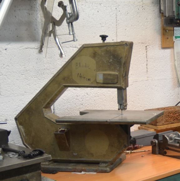
As a teenager in the 1960s I had a Burgess 3 wheeled bandsaw, which like the milling machine of an earlier post, has followed me around the world and I still use it today. For some reason, which I don't recall, I built a 2 wheeled machine. Maybe I wanted full width at full height. Back then like Vyacheslav Nevolya I used to cast stuff out of scrap aluminium and that's how I made the new bandsaw wheels. Even though I was aware that pulleys for flat belt driven machinery and commercial band saws etc. had at least one crowned pulley, but the arrogance of youth lead me to believe that I knew better. It was obvious that a hollow pulley or bandsaw wheel would give better alignment. Arrogant I might have been back then but I was also quick to learn when I was wrong and I soon remachined the hollowed out wheel to a crown shape and had no further problems of flying bandsaw blades.
Here is a pic. of the little Burgess as it is today. I don't seem to have photo of the homemade bandsaw.
As an inquizitive lad I searched books (yes, the internet has not always existed) in the library for an explanation of this seemingly counter intuitive behaviour, but found no answer. So I adopted my usual approach with such mysteries, that is I would lay awake in bed turning it over in my mind. One night it all clicked into place and I was a happy boy. However, back in October of this year during discussions with friends the subject resurfaced but I had forgotten the explanation. So back to a couple of sleepness nights to rediscover the mechanism. I hate to leave such matters hanging.
So here is the flat belt on crowned pulleys explanation. I had to get it written down before I forget again and have to go through the mental gymnastics when the topic next resurfaces.
The "trick" to it all, is to realise that the belt velocity is constant across its width but the pulley velocity is not. Then the relative velocities between pulley and belt work out in accordance with observation.
It is easy to look at it in reverse and think that the part of the belt on the larger diameter is moving faster than the part of the belt on the smaller diam. That leads to the conclusion that the belts would fly off a crowned pulley, which I think is the intuitive reaction of most people. We know different though.
To get an idea of the mechanisms at work we only need look at the crowned pulley not any parallel pulleys in the loop.
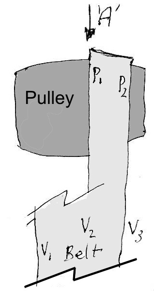
Firstly, let us consider only a slice of half the width of the belt passing over just one side of the pulley as in Fig.1.
Fig.1.
If we consider the linear velocities across the width of the belt, say V1, V2 and V3, shown near the bottom of Fig.1, we can see that they must be equal or the belt would be tearing itself apart. We known that is not happening. In other words the linear forward velocity of all points on the belt must be equal.
Now consider the circumferencial velocity of the pulley surface at points P1 and P2. Due to different diameters at these points it is obvious that P! has a higher velocity than P2.
The only way that we can reconcile this with a belt which has a constant velocity across its surface is to realize that over most of the contact area between belt and pulley there is slip of varying magnitude.
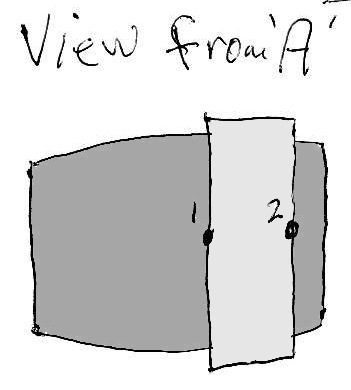
Fig.2 shows us a view looking from "A" in Fig.1.
Fig.2.
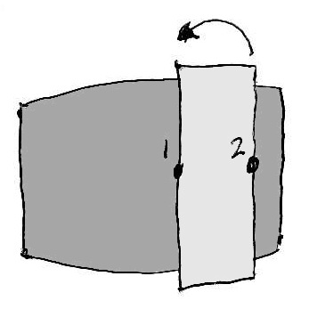
It is reasonable to assume that somewhere around half way between points 1 and 2 the belt and pulley surface will be travelling at matched velocities. So at point 2 the belt will be travelling faster relative to the pulley surface and at point 1 the belt will be slower than the pulley. This means that the belt will be trying to climb up the crown of the pulley, as in Fig.3. Think of a car in a curve, the outer wheels will be travelling faster that the inner wheels. The belt is like the car and the pulley surface is like the road surface.
Fig.3.
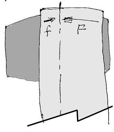
Let us now put a new full width belt on the pulleys in place of our sliced belt as in Fig.4.
Fig.4.
Imagine that we did not put the belt on properly and it is a little offset to the right. We have seen that the crowned pulley produces a force tending to force the belt towards the crown. The wider the section of the belt on one side of the pulley the greater the difference in velocities between the outer edge and the inner edge and hence the greater the force. So in Fig.4 we can see that the force "F" on the right hand side is greater than "f" on the left side. This force imbalance will make the belt move toward the left until f = F or in other words the belt becomes centralized over the pulley. That is it automatically corrects any errors of alignment.
This is in accord with our experience.
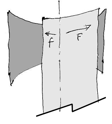
Intuition often leads many (including me in my naive and inexperienced youth) towards the idea that a hollow pulley would centralise a belt. However, anyone who has tried this will have learnt very quickly that it doesn't work. Looking at Fig.5 we can easily see why.
Fig.5.
As in the preceding explanation we can see that if the belt is not perfectly centred there will be unbalanced lateral forces acting on each side of the belt. This time the forces will act outwards rather than inwards as before. So when F > f as shown the belt will be flung off, which is exactly what anyone knows who has tried such pulleys. It reinforces any intial alignment error rather than correcting it.
QED.


 Reply With Quote

Bookmarks