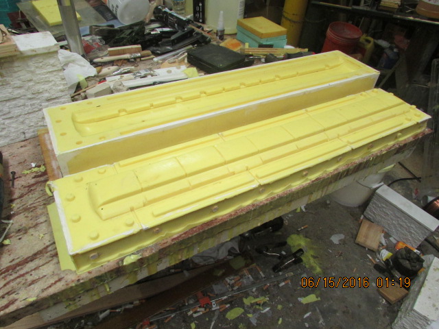
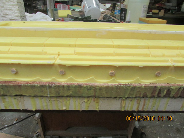
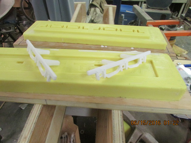
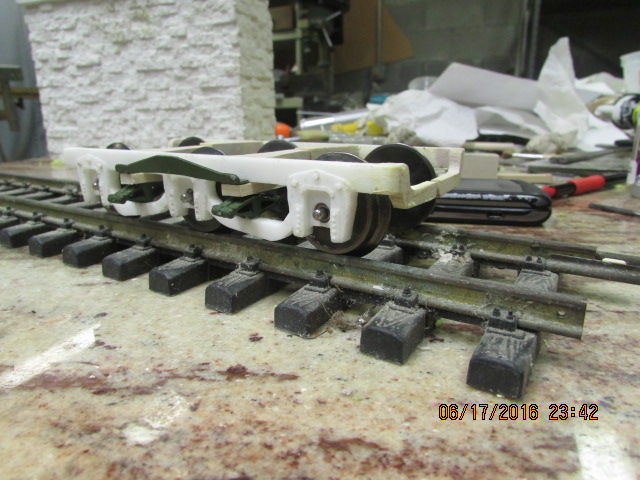
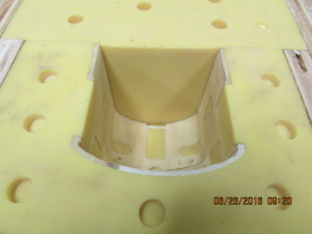
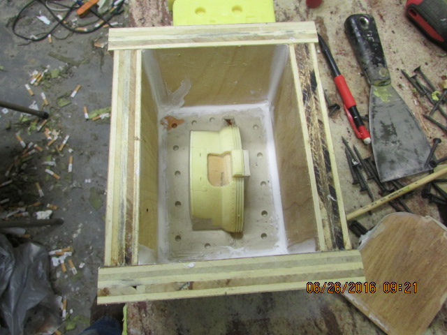
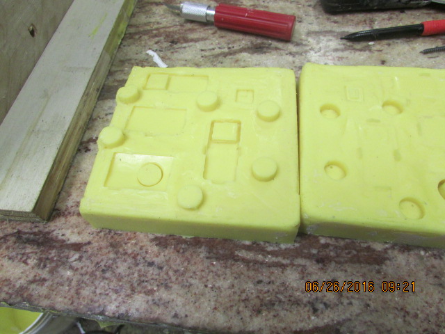
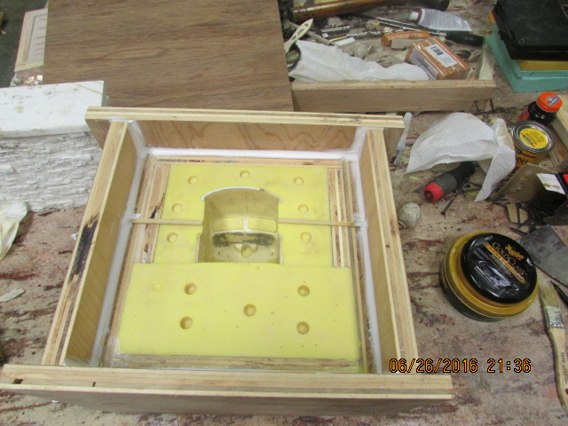
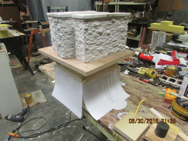
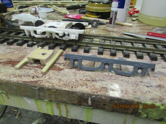
Couldn't be a better day, the top roof mold came out perfect. Made two sides for the truck and they also came out good, ready to make some more parts for the truck. Bob.Attachment 11521Attachment 11522Attachment 11523
Printable View
Couldn't be a better day, the top roof mold came out perfect. Made two sides for the truck and they also came out good, ready to make some more parts for the truck. Bob.Attachment 11521Attachment 11522Attachment 11523
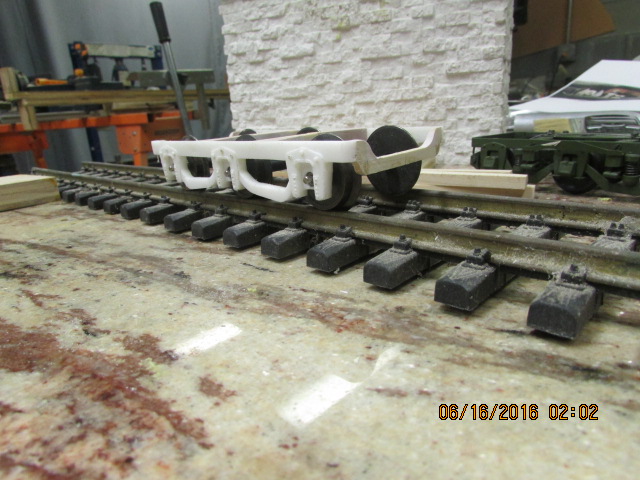
More solidity for the ends. Bob.Attachment 11526
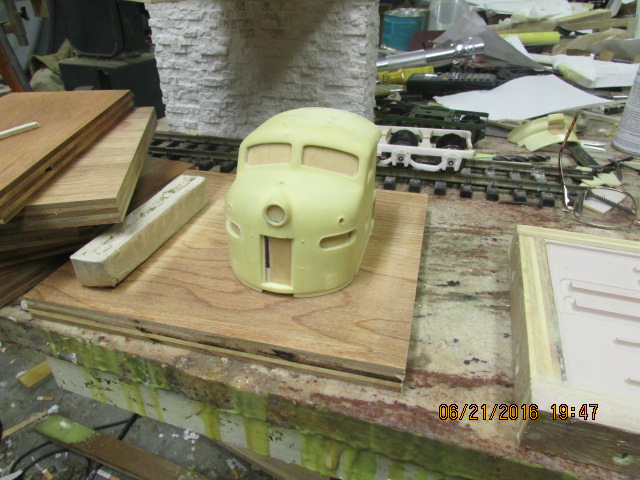
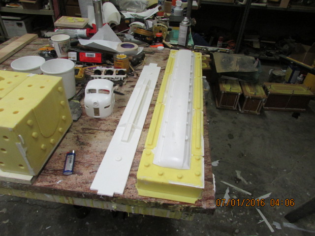
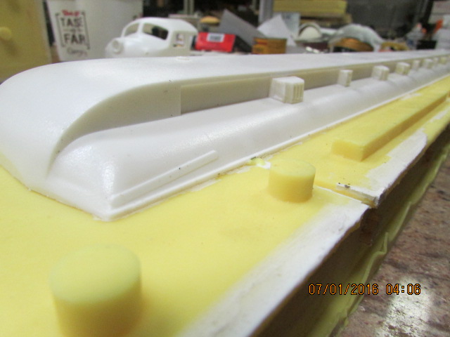
Continuing to mock up, almost there, waiting for some more urethane. Bob.Attachment 11607
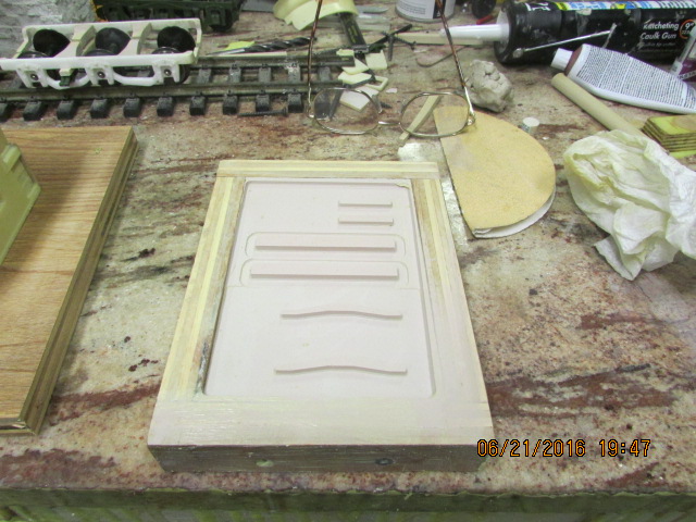
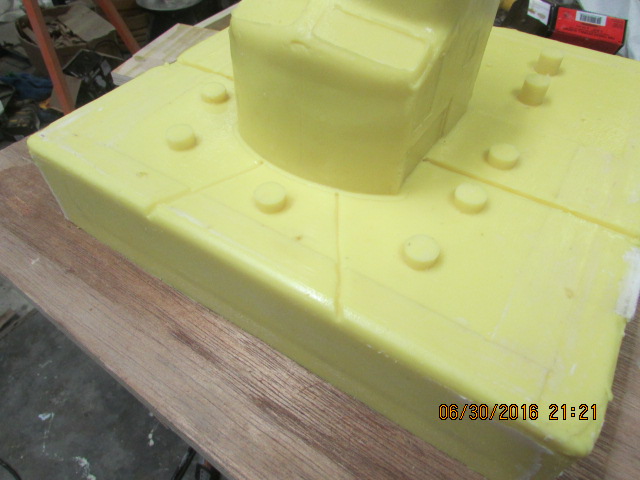
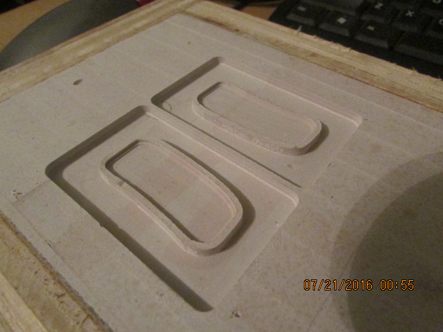
Attachment 11866Attachment 11867Here is another pattern done on my mill in Bondo for some more parts for the truck and another project. Bob. Thanks Paul.
Bob,
Nice work on the trucks to ensure precision alignment (and smooth operation without derailments). I like the beginning work on the diesel cab unit. Is that for an F7 EMD locomotive A unit? That will be a fun project. I can just see an A-B-A consist pulling a string of your heavyweight passenger cars.
Thanks for the updates.
Paul
Yes Paul, this cab was used on F and E-7, E-8 and E-9 units. Bob.
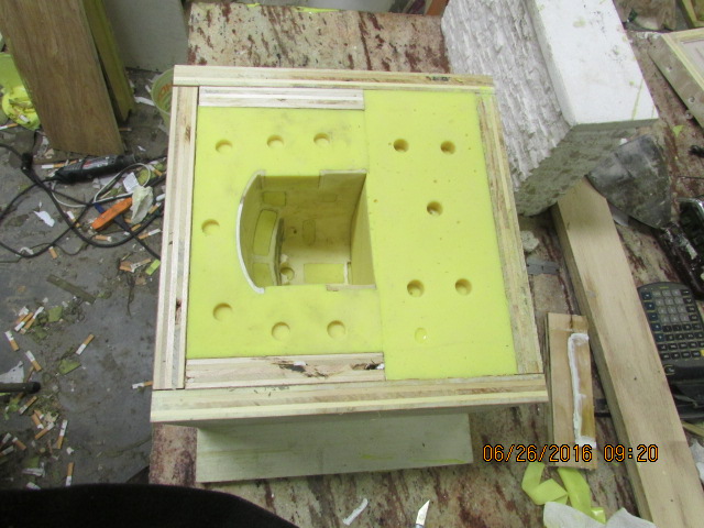
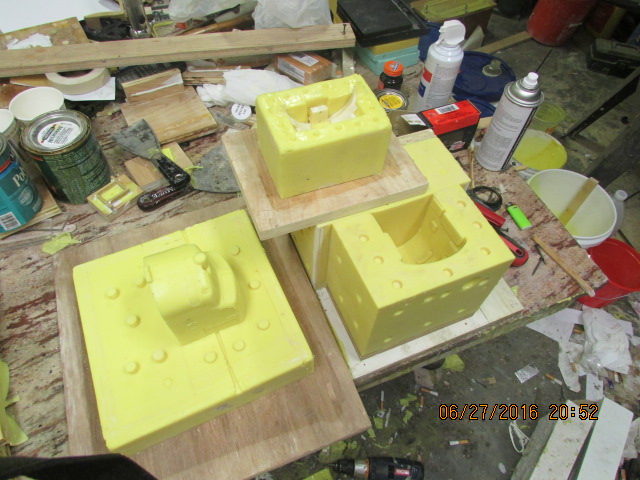
Here are some more molds of the f-7/e-8 cab and parts. Tomorrow, I will pour the third part to the mold for the cab and the front skirt. Bob.Attachment 11947Attachment 11948Attachment 11949Attachment 11950
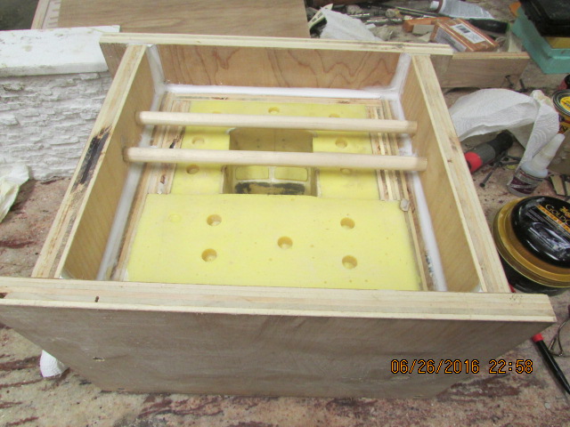
The mold is ready to pour the third and final part of the mold set. *You experienced mold makers probably already knew this, but I had to find out the hard way. *A means of reducing pressure when installing the top of the mold set is needed so that the two mold section can seat, thereby reducing the chance of making too thick of a part and not retaining the desired shape. *Note the two channels glued to the highest part of the mold allowing the excess plastic to escape. *Not all is lost on my previous molds, because I can still cut a channel in the top pieces of the molds to achieve the same thing, which I will do on the side molds where that was a problem, so I just thought that I would pass this along in case any one out there is making molds. *In case someone is wondering if the the thickness of the walls will be retained, and the answer is, yes, note that the cab pattern is in the first part of the mold and by pouring the third part of the mold the walls will be retained. *The only reason I shared this is that someone asked if I was going to pour it solid, he didn't see that the cab pattern was still in the mold. The third part of the mold is to establish the thickness of the walls. *This mold set has three parts to allow removing the part once the pour hardens, it would be difficult to remove if only using a two part mold. Bob.Attachment 11959
Hey guys, you forgot to tell me to put the bridge dowels in the third part of the mold, but that is OK, I remembered. *They might not have been necessary, but any help to prevent say in the mold is good, even a 1/32 of an inch is too much. *It also helps, when the plastic is poured in and the mold is compressed downward, it is solid and prevents compression, here is a picture. Bob.Attachment 11960
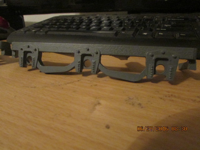
Here is the first side rail out of the mold. Still making more parts for it, spring holders, leaf spring etc. Bob.Attachment 11961
Half of the front skirt and all of the cab mold completed, Bob.Attachment 11985
A mock-up for fitting some more parts. Bob.Attachment 11992
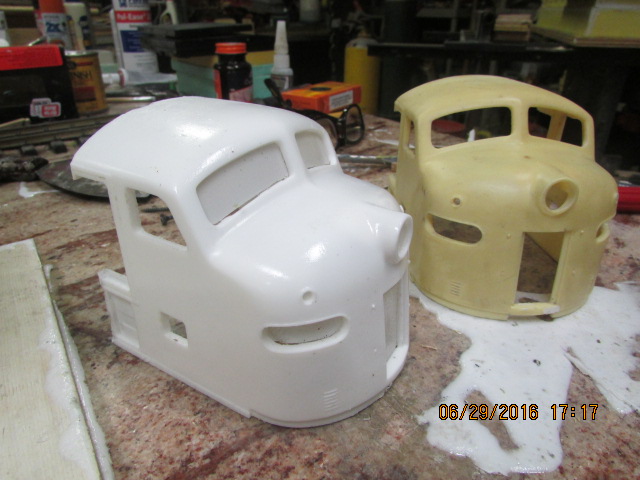
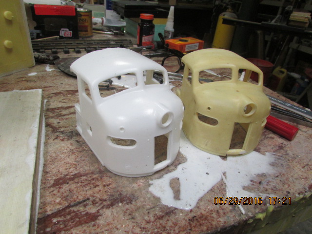
Thanks Paul. Attachment 12034Attachment 12035Attachment 12036Here are some pictures of the completed cab part from the mold. *I will also have to make a pattern for the straight type pilot. Note the amount of flashing, minimal, it just fell off and that's good, shows that the mold parts are fitting tightly. Bob.
Bob,
The EMD E and F locomotive castings are looking very good. I know it takes a lot of work but a great opportunity where you can have a hobby and business that is fun. Thank you for showing your progress.
Regards, Paul
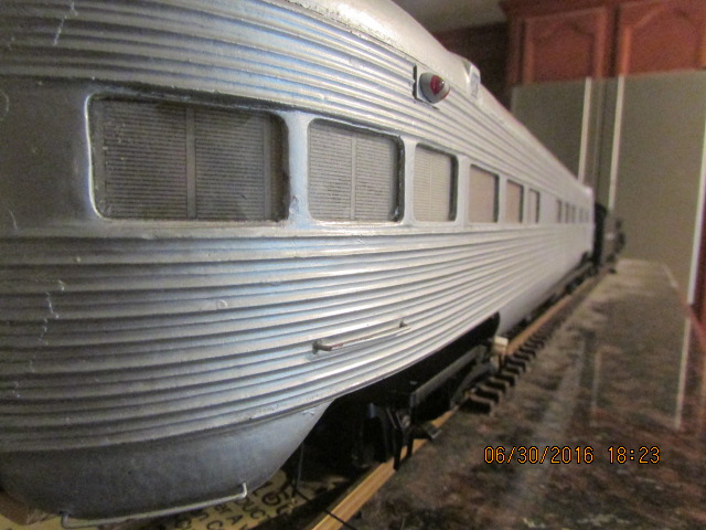
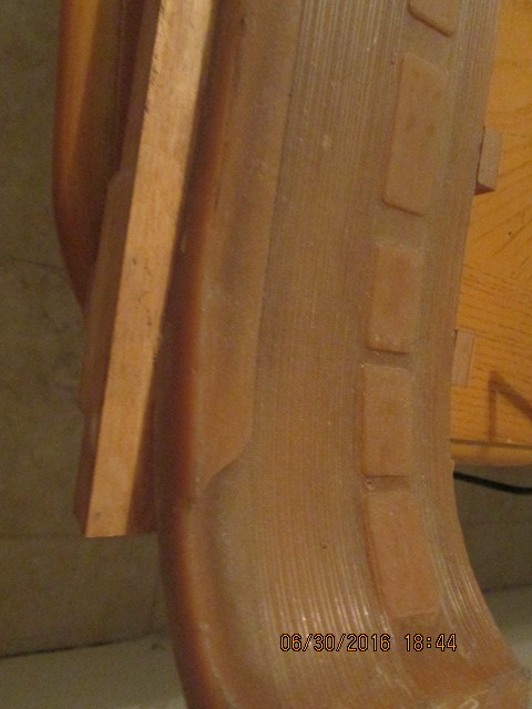
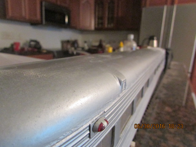
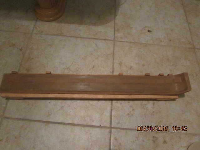
I wanted to share this with you. Back in the days when I didn't have any machines, such as, a lathe, a mill, a cnc router, or a 3D printer, which I still don't have, I made patterns out of wood with just a hand held router and a band saw. While this 1945 Pullman observation is not perfect, in my estimation, it still looks good. The fluting was made with a bullnose 1/8th inch router bit, spacing with different thickness plastic spacers on a jig that I made. The roof shape was made with 1 inch sections of wood. After the patterns of the sides and roof were made, an epoxy mold was made. I made the mold long enough for the round end and a straight roof, which I still use today. My point is, one can still make models without all of the fancy machines. Bob.Attachment 12050Attachment 12051Attachment 12052Attachment 12053
Some bubbles occurred in the last pour of the cab, so I added some some relief channels to the upper most part of the mold where the bubbles occurred, so I hope this cures the problem, I will know later on today, and also I have been taping paper, with vinyl caulking, since the tape won't stick to the waxed wood, to make the cleaning of the molds easier, works good. Bob.Attachment 12054Attachment 12055
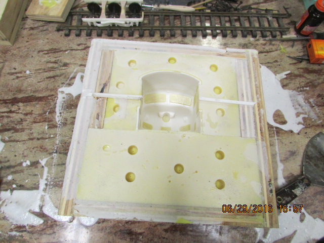
I couldn't wait, so I pulled the parts out of the molds, the chassis and the roof came out perfectly, but still having some small bubble problems in the cab. *None of the bubbles are bad enough that they can't be repaired, but I would like a bubble free part, here are some pictures. Bob.Attachment 12092Attachment 12093
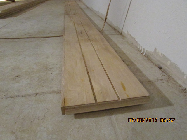
Thanks Paul. I am sure that some of you have done this before, but I haven't, so I did. I had to get my trains off of the floor, so I cut a piece of plywood, 4x8, into 8 lengths and grooved them for track, saved about 300.00. The eight pieces gave me 64 feet of shelving. Bob.Attachment 12114
Thanks Paul. Just an update. Poured another 15 lbs. of urethane today for another heavyweight side, some parts for the truck, pilot for the cab,**and*reduced a*three part piece for the truck to one piece, starting the mold today. I keep forgetting to tell you this. *I don't know how many of you are using urethane, but if you do, this procedure was recommended to*me by the seller. *Part A, that is the hardener, to keep water vapor in the air isolated from the urethane, after opening, a shot of nitrogen should be shot into the bottle to preserve the hardener and to give it more shelf life. I found out the hard way, without that shot of Nitrogen, the hardener will gel much faster. *The part B doesn't need this step. When they ship it, a shot of Nitrogen is already in the bottle, but once opened, you have to do it again. *The Nitrogen is heavier than air, so it isolates the urethane from unwanted moisture in the air. *Urethane, in contact with air, causes the moisture to get into the urethane and causes air bubles in the urethane, just something that I had to find out the hard way.*Bob
Bob,
Good advice for using nitrogen to slow down the aging.
Thanks for the updates, Paul
Thanks Paul, I have noticed that procedure helps. Attachment 12241Here are some more parts for the truck, still mocking up. *I combined the spring cross bars with the mounting plate, so it makes it a little easier to assemble. Bob.
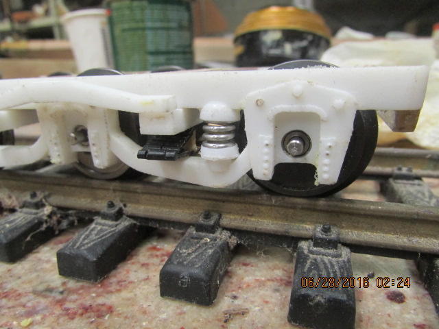
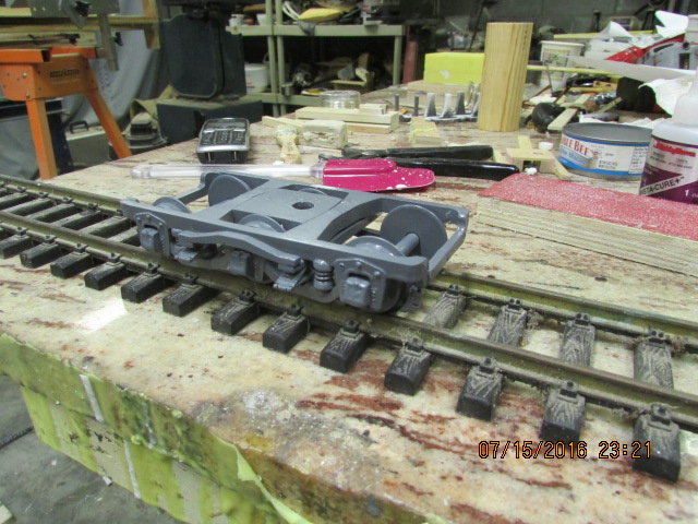
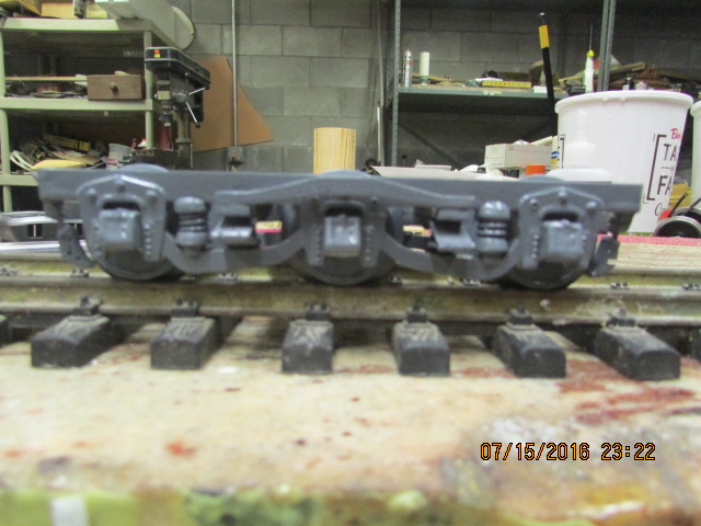
Thanks Paul. The mock up of the truck is finished, here is the truck. BobAttachment 12434Attachment 12435Attachment 12436
Bob,
The trucks look impressive. Looking forward to seeing these on the heavyweight passenger cars.
Paul
Thank you Paul. I am gearing up to make the cars shortly, Bob.
I have been trying to get the perfect shape for the F cab windshield and I made a pattern for a mold. The shape has been scaled from the full size to 1:32 and is made with the seal. I loaded the program on my Anilam controller and had to delete all of my other programs just to get this file on my machine, about 4000 steps.Attachment 12516 Here is the beginning of the operation. Bob.
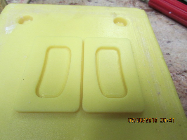
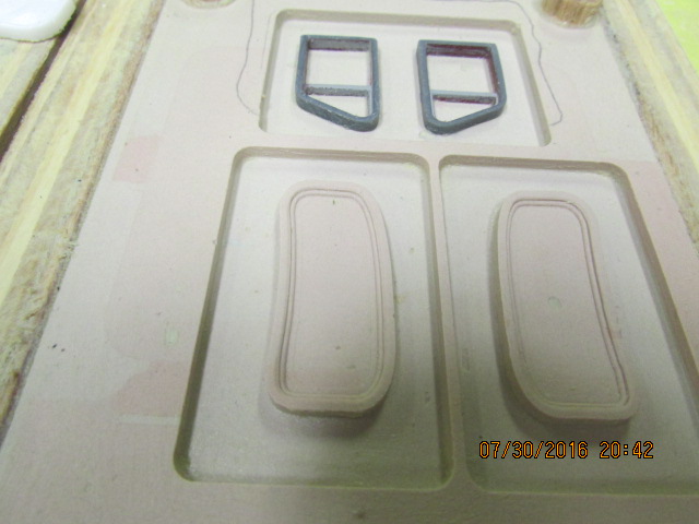
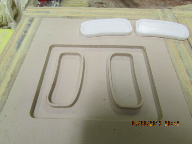
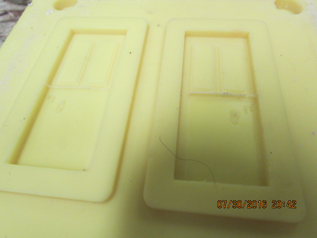
Here is what I have been doing in the last few days. I made a mold of the heavyweight doors so that they will open and be a split door. *I am still trying to make the perfect E and F series windshields. *I am trying to make the windshields, so that I may retro fit them into any one gauge E or F series loco. *I am designing them so that when installed in the loco, there will be no glass to make it easier for painting and then there will be a ring in the shape of the windshield, to be installed from the inside to hold the glass in. *I am using .020 Lexan for the glass, also making the side windows for the loco, and here are some pictures of the patterns and molds. Bob.Attachment 12766Attachment 12767Attachment 12768Attachment 12769
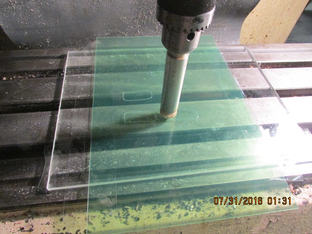
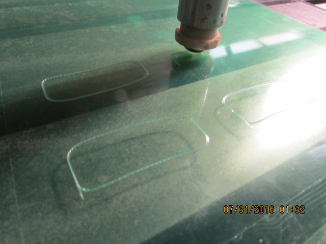
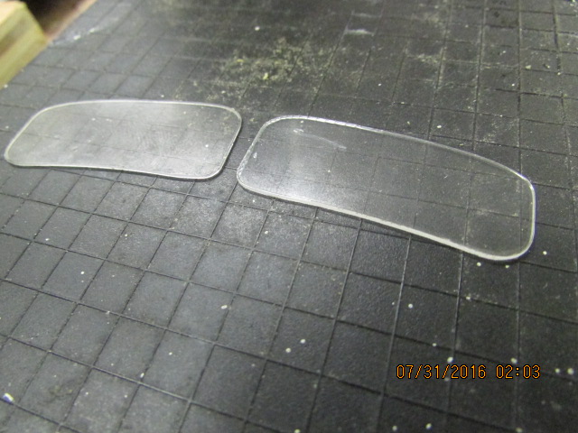
Attachment 12770Attachment 12771Attachment 12772 *Well here are the glass panels. *I cut them with a tool that I made, a vinyl cutter. *This tool was made to cut just .005 material, but I ran it through twice and it scored the .020 Lexan enough so that it broke away clean. They came out just like I wanted them to. *I have to draw just one more part to complete the assy. then I will attempt to install them in an MTH cab and the other cab that I made the mold for. Here are some pictures. Bob.
Bob,
I like your clever use of the "scoring" method with the CNC inscribing technique. This would be very precise for any type of model making.
Thanks Paul
I should have described the cutting tool a little better. The blade in the cutter rotates 360 degrees and protrudes about .005 in. The blade is mounted with a spring loaded pad and moves about .250 in. for uneven surfaces. The blade was purchased at a vinyl cutting supply store and adapted to my tool. Thanks Paul. Bob.