VERY VERY NICE!!!!! A labor of love for sure!!!!
Printable View
VERY VERY NICE!!!!! A labor of love for sure!!!!
That is awesome!!!
Great to see it get this far.
An engine removal thingie I made. 'Thingie' is a technical term for engine crane. XS650 engines are a very tight fit in the frame, only mms to spare, if you want to work on anything aside from the clutch and alternator,the engine must be removed from the frame.
The Thingie works quite well: Lifts the engine and tilts it forward so it can be rolled away from the frame without scratching or damaging the paintwork.
The thingie also doubles as a work stand for top end rebuilds.
When I've finished with the current work, I'll modify the stand so the engine can be mounted longitudinally in the thingie and rotated upside down to disassemble the bottom end.
Once the motor has been disconnected from all electrical inputs and front, rear and top engine mounts removed, the motor can be removed from the frame in around 5-10 minutes.
Very nice. Works perfectly...
Well that sure did take a bit thoughtful creative thinking!!
Wow, such a simple thingie ! I assume that just popped into your head and was made in an hour.
Some single use thingies: A cam chain holder to stop the chain dropping into the sump all the time. Better than string or wire because the motor will turn over.
A TDC finder. Made of an old plug which I threaded M10 internally, screwe a bolt in place, drilled and tapped that and screwed in a long M6 bolt.
The degree wheel is held in place by three rare earth magnets, it has marking for TDC and other markings 5 degrees apart up to 40 degrees. The short piece of tube, fits in the central hole and is a tight fit around the socket for centering. Once centred, it's removed to give the socket a little wriggle room.
When I got the bike the cases had been damaged (read - rooted) by an errant chain. Along with that, the alternator cables had also been cut by the chain and the chain deflector, or whatever you call that thing residing over the gear lever pivot, was also stuffed.
Rather than stick with the original design, I turned up a one piece Delrin bush which slides over the gear lever shaft. Rather than hide the alternator cabling behind the chain deflector, I rerouted the alternator cabling so it is underneath the gear lever shaft and held in place by a P clamp on the starter gear cover.
You may also be interested in making rubber grommets. In the pic you can see the rubber grommet through which the alternator cabling is routed. These, and other grommets, are super easy to make: A fibre cut off wheel and belt sander being all you need. Plus a good set of eyes, or in my case - glasses! The fibre cut off disks are good for cutting the slot, and either the cut off disk or belt sander to shape the outer circumference. Spinning rubber on a lathe does not work well, trust me!
After shaping the grommet, the groove or slot in the grommet is best made by mounting it on a piece of round stock and rotating it against the cut off wheel. Cut of wheels are generally available in two thicknesses 3mm and the much thinner ones used on small angle grinders. Obviously a good, solid rotating base will result in a better groove or slot. With a bit of practice , they are easy to make and come out as good as a bought one. In Oz, blocks of rubber are available from Clarks Rubber. I'm sure in whatever country you live there will be similar stores.
Never buy what you can make.
<!-- BEGIN /var/www/html/homemadetools/protected/modules/zeus/views/tool/postUpdate.php -->
Thanks th62! We've added your Cam Chain Holder to our Motorcycle Engine category,
as well as to your builder page: th62's Homemade Tools. Your receipt:
<div id="blocks"> <div class="block b1 pngfix"> <div class="bimg"> <div> <a href="https://www.homemadetools.net/homemade-cam-chain-holder"> <img src="/uploads/260791/homemade-cam-chain-holder.jpeg"/> </a> </div> </div> <div class="head pngfix"></div> <div class="left pngfix"></div> <div class="right pngfix"></div> <div class="blockover b1 pngfix"> <div class="title"> <a href="https://www.homemadetools.net/homemade-cam-chain-holder">Cam Chain Holder</a> <span> by <a href="https://www.homemadetools.net/builder/th62">th62</a></span> </div> <div class="tags">tags: <a href='https://www.homemadetools.net/tag/engine'>engine</a> </div> </div> </div> </div>
<!-- END /var/www/html/homemadetools/protected/modules/zeus/views/tool/postUpdate.php -->
<!-- BEGIN /var/www/html/homemadetools/protected/modules/zeus/views/tool/postUpdate.php -->
Thanks th62! We've added your Motorcycle Engine TDC Finder to our Motorcycle category,
as well as to your builder page: th62's Homemade Tools. Your receipt:
<div id="blocks"> <div class="block b1 pngfix"> <div class="bimg"> <div> <a href="https://www.homemadetools.net/homemade-motorcycle-engine-tdc-finder"> <img src="/uploads/260797/homemade-motorcycle-engine-tdc-finder.jpeg"/> </a> </div> </div> <div class="head pngfix"></div> <div class="left pngfix"></div> <div class="right pngfix"></div> <div class="blockover b1 pngfix"> <div class="title"> <a href="https://www.homemadetools.net/homemade-motorcycle-engine-tdc-finder">Motorcycle Engine TDC Finder</a> <span> by <a href="https://www.homemadetools.net/builder/th62">th62</a></span> </div> <div class="tags">tags: <a href='https://www.homemadetools.net/tag/engine'>engine</a> </div> </div> </div> </div>
<!-- END /var/www/html/homemadetools/protected/modules/zeus/views/tool/postUpdate.php -->
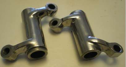
Coil bracket.
When I converted to a single,points system I had to install a dual output coil. I opted for a Honda 750 coil and welded tabs on the frame on which to mount it.
The coil lasted all of two weeks, so I ordered another the same and installed it. It's still ok, but I have heard this particular coil is known for a short life. With this in mind, I found another type, still for a Honda 750, and ordered one. When It turned up, I discovered it was about 20mm longer than the other, so, the tabs I welded on the frame were too close to allow fitment.
So, I cut the rearmost tab off the frame, jumped on the mill and machined this bracket. The bracket clamps around the short frame tube under the main top tube and can be slid forward or backward to fit either coil.
I've been ruminating on fitting the TX650.with a hydraulic clutch actuator for some time. Originally a plastic screw type actuator was fitted. The clutch action is a little heavy for my arthritic fingers and difficult to operate as my fingers are fused. At first I modified a spare screw actuator by lengthening the lever, it worked ok, but I'm not a fan of screw type actuators, so, I set about making a hydraulic actuator. I worked out I could fit a hydraulic slave to the inside of the side over with a max piston size of 25mm, requiring a master with a piston of around 10mm. That being the sticking point.
I finally found a master cylinder that 'should' do the job: Its for a KTM and has a 9.5mm piston. Its on order and should be here in a a couple of weeks, along with a couple of banjo fittings. Fitting the slave behind the cover seemed the best idea, as it provided a good solid stop against the clutch spring pressure and would be unobtrusive.
Unfortunately, I couldn't find a clutch master that matches the brake master of the right size, so I've decided to make a feature of having non matching masters. To that end, when the clutch master arrives, I'll polish the body, and then order a radial brake master and polish that, you can't get much different than these two masters.
So, the last couple of days I've spent on the lathe and mill building a slave cylinder and modifying the side cover to fit it: Lots and lots of setting up to ensure the holes are in the right place and everything fits. Lots and lots of swearing and cursing as well.
The piston is phosphor bronze, 25mm diameter and 28mm long, drilled 8mm to a depth of 20mm to take an 8mm ball and the 8mm push rod. Turning and milling the slave was a barrel of fun: I started with a small block of 50 mm 6061, faced it and bored it out to 25mm to a depth of 26mm, then enlarged the first 6mm to 33mm to take a hydraulic ram seal. The seal has a locating lip, so, I had to grind a tool to the ssame shape as the lip to turn a locating groove. And wouldn't you know it, in a moment of senility I turned the groove at the bottom of the 25mm bore, instead of the 33mm seal bore. Oh well, I fitted an O ring to the mistake groove and I'll tell anyone that doesn't know any better the O ring is to soften the rebound.
After the bore was done, I turned the slave around, chucked it and turned down the other end to 29mm for 18mm, drilled and tapped to 10 x 1.25mm, then faced the end.
I had to mill 3mm off the 50 mm diameter end so it would fit in the side cover. Once that was done, the side cover was mounted on the mill and the 26.5mm screw actuating hole was bored out to 29 mm to fit the slave cylinder. The slave was fitted and the two mounting holes marked on the slave, then the slave mounting holes drilled and tapped to 6mm x 1.00 to a depth of 10mm, a mm or two short of the ram seal bore . The slave mounting holes on the the front of the side cover were then milled for clearance to take the allen screw heads.
The slave is mounted where the original screw actuator sat, so space was tight. It's a rather dirty environment behind the cover, so I may have to fit a cover over the seal end to keep it clear of dirt and grease. I'll also have to turn up two half circle Delrin spacers to fill the gap between the slave and the cover to make it look a little neater.
Here's lots of pics of the build.
Very neat installation. Those Japanese screw clutch actuators are horrible, especially after a bit of wear from use. Hydraulic actuation wastes much less of your hand effort.
I get those "moments of senility" quite often.
I had a YZ250 from the early 80s that had to be adjusted about every week. It was brutal. I got really good at removing and reinstalling the clutch cover.Quote:
Originally Posted by tonyfoale
Yesterday I made another twin lobe points cam. The original I made worked fine, but was slightly out, so I did a little more filing, too much ask it turned out, a few swipes with a file took it past the midway point on the backing plate adjustment.. I've made a few of these points cam, very difficult to get accurate, one swipe of the file can ruin a hole days work. But this one I got spot on for both cylinders. Today, I made a clamp to hold a bit of felt to lube the cam, very small exacting work. After all that I polished the cam and backing plate, just because something isn't seen doesn'mean it shouldn't be shiny. I once polished the rocker arms on a Bonny.
I did the same polished rocker arms Attachment 47050on my T100SS just for the pleasure of knowing its in there looking good.
Polishing internal parts is much more than just visual obsession. It has profound effect on performance. When done properly it also makes parts stronger. This may be counter intuitive, since material is removed during the process. However, by removing surface imperfections, you also remove places where fatigue cracks can begin to form.
For reference, try to break a piece of glass, then scratch one just like it and notice how much easier it is to break. It also enhances oil flow. There is some research however to indicate that polished intake runners in carbureted engines can cause fuel to condense rather the stay atomized in the intake stream. I do not have enough information to say ya or nay on that..
Many connecting rods and other parts in modern high performance and race engines are aluminum, or titanium, forged or CNC machined from a forged billet, then polished in Giant Finishing Machines. Back in the day, us poor unfunded hot rodders would polish stock rods and other parts by hand to make them stronger.
We even polished entire engine blocks, cylinder head, rocker arm surfaces, etc to allow oil to flow more freely back into the oil pan. At high RPM it is possible to pump all of the oil out of the pan because it pumps out faster than it can drain back down.
Giant Finishing, has a whole series of videos on youtube about vibratory finishing. If you are interested, put Giant Finishing Episodes in the YouTube search bar. Then click VIEW ALL EPISODES. This will show you the whole list.
Two videos specifically related to this topic are;
66 Giant Finishing - How To - Finish Connecting Rods - Part 1 and 67 Giant Finishing - How To - Finish Connecting Rods - Part 2
There are many other videos of cylinder heads, crankshafts, valves, headers, etc.
After a while they get a bit repetitive, but at least for the 66 and 67, be sure you have the sound turned on and watch at normal speed. I won't tell you why, you can be surprised. Being pleased or not, will depend on your age :)
It's not stronger (you are not changing the composition of the material) but you are increasing cyclic fatigue life.
The morons have invaded.
Ultimate tensile strength increases as well. Probably doesn't help when a material is in compression, but tension, shear and bending can be improved. Surface imperfections cause stress concentrations when materials are mechanically loaded, which act as a "nucleation point" for failure.Quote:
Originally Posted by Saltfever
...but if you're running that close to the limit you probably have other issues. I have never polished something with the intention of making it stronger. Just make a better part.
Give it a rest morons, I think you have stroked your egos enough.
That's three more added to the idiot list. I really don't understand these morons that need to stroke their egos all the time, then move onto stroking something else.
For the morons, who obviously think they know something nobody else does, polishing conrods for example does not increase strength it simply removes defects from the surface thus preventing cracks starting. Shot peening does pretty much the same thing. Polishing rocker arms on the other hand is purely for aesthetics. Itnalso does notndecreasebstrength. By polishing the metal you are simply removing the high spots thus levelling the surface. The high spot have no value in terms of strength.
Don't bother replying and stroking yourselves any further, I have added you to the idiot list, ie, the ignore list.
More on the hydraulic clutch conversion. A total fup!
This is a new 20mm clutch slave cylinder I machined up for my 74 TX650 to replace the 25mm slave I made. The 25mm slave didn't work as the piston only had around 1mm movement using the 9.5mm master I bought.
The new 20mm slave was machined up from piece of 6061, the piston is 304 stainless and the seal used is from from a hydraulic ram. Instead of using a circlip to retain the seal, I machined a cover to both keep the seal in place and also to act as a dust seal.
To fit the slave I bored out the actuator hole in the clutch cover from 26 to 29mm and drilled the M5 threaded mounting holes out to 6mm and bored them to take allen heads.
The 9.5mm master I bought for it was advertised as using mineral oil, which suited me as I dislike using brake fluid. Unfortunately, the ad was wrong, I used mineral oil and the piston seals swelled up and jammed the piston. WhenI finally managed to get the piston out, one of the seals was damaged, rendering the master useless.
Replacement seals are unavailable for this master, so I decided to retain the screw actuator. This engails returning the clutch cover to original. To do this I turned up a couple of stainless 6mm T nuts and threaded them M5 and pressed them into position. I then turned up a Delrin spacing ring for a press fit around the screw actuator.
It all works as it should now with no obvious signs of the modifications I made. And now I have a 20mm clutch slave sitting in my useless parts bin.
So, all for nought... I'm now back to the original cable actuated clutch.
Great job! Looks perfect...
Superb job.
Beautiful! You've done a great job!
Very nice, though I'd recommend an oil filter guard, as a small stone puncturing it might only become apparent as the rear tyre loses grip and things go pete tong. Many BMW F800 owners can tell you that story!
A beautiful bike! What are the cylindrical parts mounted at the top of the rear shocks?
Air or nitrogen sealed pressure chambers. The gas pressure is to stop or reduce the tendency for cavitation in the damping oil. This is very common with any quality shocks but some incorporate the gas chamber within the body of the shock and some do it in a remote cylinder connected by a hose.Quote:
Originally Posted by Floradawg
And some of the cheaper ones are BS, just for show. Fortunately, mine are real.
Very well done! Your design concepts, even if they didnt work still benefitted us all. I certainly learned a bit from your hydraulic clutch attempt!
Thank you for sharing your beautiful project!
I made a fuel distributor a while back, its function was to level the fuel when the level in the tank dipped below the level of the tunnel and also to neaten things up. ,I had two online filters feeding fuel into the distributor.
The filters just kept cracking and leaking, so I decided on a combined fuel filter/distributor and this is what I came up with. The unit sits between the manifolds I made a while bike and is mounted in rubber grommets on a bracket attached to the cam chain tensioner.
The filter is sintered bronze and the body 6061. The bore is 18mm at the top to seat the filter and O ring, then expanded out to 23mm. There are three 6mm brass barbs pressed into the lower section, two for inlets for fuel, the third for purging debris. The top cap is retained by two M4 screws and is a push fit over the lower body, an O ring sits in a recess around the filter for sealing the top cap to the lower body.
Two 8mm brass barbs were pressed into the top cap and they feed the carbs via short fuel hoses. The cap is drilled 10mm underneath leading to a 5mm cross drilling which lead to the two brass barbs.
Very neat.
Deleted. Moving on.
Is the compression loss equal on both cylinders?
Yep, within two or three psi.
If the piston ring gap is a little too small it can cause the ring to distort if the ends meet as it gets hot. Nothing to lose by increasing it slightly, as the rings wear it gets larger anyway. You probably gapped them to spec but the problem you have exists so worth a try?.