WHY NOT, it is a joy to see how your progressing.Quote:
Originally Posted by th62
You are achieving a marvelous result with a CLASSIC motorcycle, please keep posting. :-)
Printable View
WHY NOT, it is a joy to see how your progressing.Quote:
Originally Posted by th62
You are achieving a marvelous result with a CLASSIC motorcycle, please keep posting. :-)
I would miss your posts as motorcycle rebuilds are what I am interested in. Its nice to see an XS 650 not being chopped for once and I am looking forward to the completion of your project. Its a fact that motorcycles are not of interest to many members but the techniques involved in restoring cover many areas of possible use to others.Quote:
Originally Posted by th62
Allen Millyards web site has a useful trick for finishing welds on exhaust pipes which may be of interest to you, about 9 mins in.
https://duckduckgo.com/?q=allen+mill...%3DT1aG63f_eEs
I have used this idea for refurbishing rusty kickstart levers etc.
Funnily enough, that's pretty much what I did, except I used an aluminium oxide grinding belt turned inside out. Only good for final finishing though really.
Since a couple are interested, Just a quick update: painted tank, front guard and headlight and made up a couple of headlight brackets. Paintwork yet to be polished, also have a couple of 650 stickers I'm thinking of applying to the tank. Not sure about them, don't want to draw attention away from the engine. If anyone is interested I can post some pictures and write a 'how to' narrative on making the headlight brackets.
Finally finished off the forks today, right side needed a final polish. These pics show how not to remove fork seals. Some people shouldn't be allowed near bikes, gouging the fork legs like that to get a seal out is criminal..
The damage is actually worse than the pictures show, both legs have deep gouge mark inside and outside the seal housings, one was cracked, but despite blasting the area and using a loupe I couldn't find it. I thought about cutting the top section down to the level of the top of the seal, then turning up an aluminium sleeve with a circlip groove and shrinking it over the seal housing, but, the seals were a damn tight fit and no more aluminium broke off the top. I might still remove the top section down to the level of the seal as the circlip really isn't needed, so tight is the seal fit. The stanchions have a bit of rust on them, hence the gaiters, but, I think the forks look better with them.
I had another shot at the left side engine cover. No matter how much I polished it before, the aluminium appeared stained. I've tried a nylon fibre wheel before with no luck, so this time I scrubbed it down with wet and dry then polished it, Still the same. It appears there is a fault in the aluminium, I must have scrubbed the aluminium down by at least half a mm, all to no avail. Still nice and shiny, but the staining is really annoying me. Strangely enough, whilst the other aluminium on the bike was in terrible condition, badly pitted and oxidised, nowhere else is staining a problem. It's only in sections rather than the entire cover. Nothing more I can do, so I'll have to hunt around for another cover. Japanese metals have always been of bad quality, too much junk in the casting I'd guess.
Attached Thumbnails Attached Thumbnails
I bought some modern CBX forks from a S/H parts place because I wanted the cartridge damping pieces. One pair of sliders were even worse than yours, the previous owner had actually drilled holes under the seal.Quote:
Originally Posted by th62
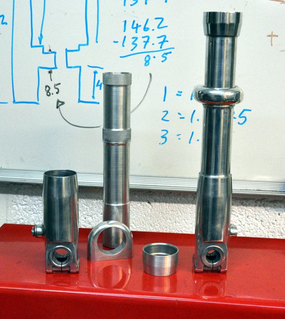
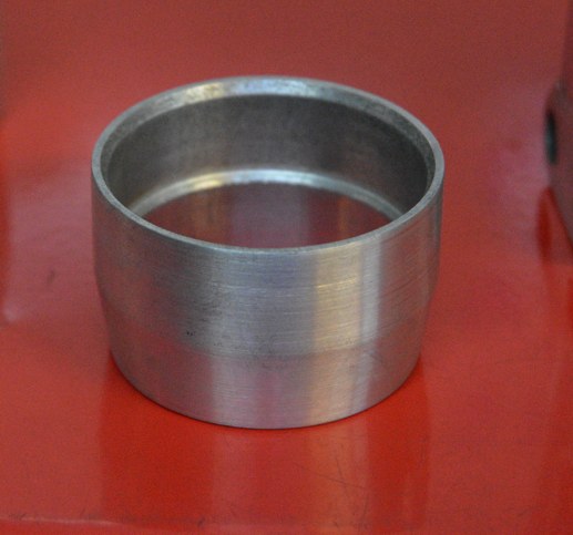
I do not know if you are familiar with the Ceriani forks of the 1960/70s (maybe earlier as well) but they were made from tube with extra pieces glued on. The glued pieces were the axle carrier, mudguard and brake torque arm mounting and the seal holders.
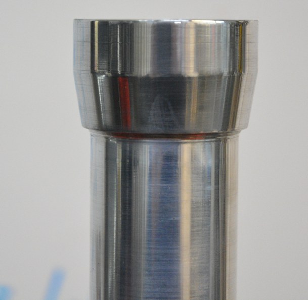
The damping pieces that I mentioned were for some replica Cerianis that I made for my classic race bike. I made the mudguard mounts and seal holders but for the axle carrier I cut the bottoms off the CBX forks which saved a lot of machining. Here are some pix.
Attachment 37791 Click thumbnails for full size
Attachment 37792 Attachment 37793
I used a size for size fit which I lightly knurled and glued the pieces on with Loctite. The knurling gave a slight interference but the main purpose was as reservoirs for the Loctite.
The Ceriani form of construction is a successful precedent to what you propose for the Yam forks. I agree about the circlip, I have never found them necessary. The only force trying to move them is friction and that should be minimal.
I agree, they look much better.Quote:
Originally Posted by th62
Shame about the imperfection in the engine cover thats the trouble with being a perfectionist I know because I am also that way. I had a similar issue with my Triumph timing cover which had a gouge across it from a probable spill. I ground a groove and used Lumiweld to fill it and flatted and polished it smooth, There is a slight colour difference in the two metals but only noticeable because I know its there. I would be interested in how you achieved such a neat bend in those headlamp brackets. I also prefer the look of fork gaiters on road bikes.
Here's how they were made. i started with two strips of 3mm ally, 50mm x 230mm. worked out PI for 34mm fork legs and did two 90 degree bends Pi apart. I used a bit of angle iron with the edge radiused for the bends as this aluminium fractures if bent to acutely. I then bent the ally around a 34mm dolly, bringing the 90 degree bends together with a 3mm gap between when clamped tight. Of course I had to stuff it all up when I shaped it, didn't I, made two right handers instead of a right and a left. The joys of getting old. Oh well, soon as I make a lefty I'll shape, drill and polish Some polishing was done beforehand for the areas I won't be able to get to after bending.. I'll post pics of the completed brackets when finished. . i started with two strips of 3mm ally, 50mm x 230mm. worked out PI for 34mm fork legs and did two 90 degree bends Pi apart. I used a bit of angle iron with the edge radiused for the bends as this aluminium fractures if bent to acutely. I then bent the ally around a 34mm dolly, bringing the 90 degree bends together with a 3mm gap between when clamped tight. Of course I had to stuff it all up when I shaped it, didn't I, made two right handers instead of a right and a left. The joys of getting old. Oh well, soon as I make a lefty I'll shape, drill and polish Some polishing was done beforehand for the areas I won't be able to get to after bending.. I'll post pics of the completed brackets when finished.
Interesting issue with the side case polishing, granularity from a cold spot during casting perhaps?
I have a fellow BMW boxer owner nearby who polished his engine (R80 sand cast casings) over a winter, had to repolish annually. Though the Ariel Red Hunter owner I met who did the same went so far the casings became porous and wept engine oil, ended up having to paint the inside with epoxy which stopped it to a degree, but as the metal was full of oil it didn't stick too well in some places. Modern water based engine paint is rubbish, my F800 has corrosion under all over, starting at any sharp edge where it's thinnest it creeps until it flakes it off, coat regularly with ACF-50 now to stop it getting any worse!
They didn't become porous they started life that way. It was a legal requirement for Brit bikes of that era to leak oil.Quote:
Originally Posted by NeiljohnUK
This afternoon I taught myself to mig aluminium. The key was finding the right volts, wire feed, stick out, speed and watching the heat build up, that had me stumped for a bit, wondered why each successive run was worse than the last - heat build up!. Oh, a steady hand also helps, but that's beyond this old codger now, hence the wobbly runs. Excellent penetration too, after welding an external edge joint, I ground it down flat then belted the hell out of it trying to separate the joint. Not too bad for an hour or so practice. A whole new world of aluminium fabricating has opened up now, should have taught myself to weld aluminium year's ago. Talk about messy though, splatter everywhere. And I burnt the crap out of my arm from flash, the flash is 10 times brighter than when welding steel.
Are you using the inbuilt wire feed or do you have a spool gun?Quote:
Originally Posted by th62
I am surprised at the dirty surrounds and splatter, are you using pure Argon or is Aluminium wire available with flux in wire like steel is? Although I have welded aluminium over 6 decades with Oxy/Act and TIG over 2 decades I have only used MIG for steel. I have seen some videos of Aluminium MIG but those showed a cleaner finish.
You have done a great job with such a small amount of practice. I relate totally with your comments on wobbly runs, being fairly ancient myself I am starting to have the same problem particularly with TIG where I have to hold the gun with one hand at least with MIG I can use both hands.
No spool gun, so I set the machine to operate properly without one: I used 5356, .8mm wire and drilled out the tip to 1mm, threw away the liner recommended for ally as too much birdnesting and used a steel liner, installed a ribbed feeder wheel and loosened off the wire reel preload.
I have tried before using a disposable argon cartridge with dismal results - not enough pressure.
Years ago I replaced the standard spiral type liner with a teflon version sold for Aluminium welding, I was welding steel but I thought that being teflon the wire would slide nicely. It did that OK but it only lasted about 1/2 day because the wire wore off a fine amount of teflon which formed a thin insulating layer in the tip preventing current flow. That was the second of two of life's lessons about teflon flowing.Quote:
Originally Posted by th62
Coming together slowly, still a lot to do, should be finished in around another 20 years at this current momentum.
I like the vise on the front disc, I'd never thought of that.
Saves on pads!
Finally decided to attach the side panels via rubber grommets inserted in the rear of the panels over the ally bungs I turned up and attached to the frame down tubes. They'll be attached to the front of the battery carrier. This gives space for pods or velocity stacks.
I did experiment with more acute angles on the side covers, a lot easier to form, but I didn''t like the look.
It's always a work of patience. I've got two Triumph on constant rebuit state because I am not always satisfied of the results hence I trash some of the work and try something else.
Welded up the battery carrier and made a security strap today. Reg/rect is mounted on a plate behind the battery carrier, solenoid is mounted underneath the carrier. Battery carrier is 3mm aluminium as is the the strap and reg/rect mount. Battery sits on an aluminium/rubber Sandwich. Front of the carrier is seen, so will be polished, remainder will be a blasted finish. Carrier sits on rubber grommets in the bracket I welded to the frame. Front mounts are bent up from 3mm steel and welded to 22mm tubes. Rubber mounts are inserted in the 22mm round tube. Still have to weld on some mounts for mounting side panels to.
This is a video of the first start up of the engine, it burst in to life, loudly, on first push of the button. This was the first rebuild, didn't like the silver colour so pulled it apart, repainted it black and reassembled. Once again, it burst into life on first push of the button. I made a wheeled stand with an ignition system cobbled together using the original regulator, a $4, ebay, three phase rectifier, a couple of Bosch coils I had lying around and a couple of switches all mounted on an ally plate and fixed to the stand. This thing vibrates, I had to tie it up to stop it jumping around the shop. https://www.youtube.com/watch?v=qm2jBGDRfPY
Since the second build I've fitted a PMA and a single points system.
This video shows my homemade manometer in use synchronising the carbs. I wasn't happy with this one, of course, since it used rubber chair stoppers to seal the acrylic tubes, so I made a second using neoprene gaskets sandwiched between to pieces of ply. The manometers are linked together at the bottom via a short plastic tube, this levels the water levels. Two long lengths of plastic tube emanate from the top of the tubes, these are fitted with .8mm jets I made up from Delrin, these even out the vacuum pulses, keeping the fluid levels steady and stable.https://www.youtube.com/watch?v=SWPGzy3BzCM
Polished the front of the battery box and the side cover, rest of the box was bead blasted. Just a rough job, but I wanted to see what it would look like on the bike. Not liking it so far, so I think I'll be making a steel box and painting the side panels black. I'll wait until the pods arrive though so I can see what the whole setup looks like together.
It is difficult to make any battery box look attractive but having made such a good lob of it if you dont care for the polished finish why not just paint it black and save re making it in steel. Same goes for me on the side panels as the polished finish draws the eye away from the nice looking engine.
I did a K&N pod conversion on my old 2001 ZRX1200 naked bike and the polished look didn't fit the bike, so I roughed it up and then painted it with black spray can bed liner. After a couple of coats, it looked just like a semigloss molded plastic box and fit nicely. Polished looks great on your bike, but it's an option for smaller parts that need to blend into the background.
Nice job on your bike BTW, been following it for awhile. I have a 1971 Honda CB175 that I have been thinking about turning into a cafe bike, but I don't want to cut the original frame. I may try to find a different frame to cut. Keep up the good work!
Finished both side panels, battery carrier, battery strap and mounted the reg/rect and solenoid. Very neat so far. Battery carrier is mounted in rubber as are the side panels. Took a bit of doing but eventually I got the side panels to mirror each other.
Here's a selection of positive stop grommet nuts. Whenever mounting anything in rubber it's important to ensure the grommet is compressed the ideal amount, too much and the rubber will distort and eventually destruct. Too little and the mounted item will move and vibrate, negating the effect of rubber mounting and also eventually destruct. Not a new idea, the Japanese have been using it for years on their bikes. Particularly helpful when mounting things on bikes prone to vibration, 360 degree twins are a good example. In this selection I turned up on the lathe, the bullet headed one on the right is thread for bolting to a frame tab, used for mounting side panels, the grommet in the side panel just slips over the bullet head in a tightish fit, the front of the panel has two grommets secured by grommet bushes and allen head bolts. Next one is a threaded, positive stop, through nut I used for a similar purpose. The third is a grommet bush with a 6mm through hole, this one is used for mounting the seat. The bush is mounted in the grommet in the seat and an allen head screw passes through the bush and threads into a tab welded to the frame. The last is a grommet bush with a 6mm through hole, turned up from delrin. This one is used for mounting the aluminium battery carrier I welded up. As the battery poles are very close to the side of the carrier, I didn't want it shorting out if a nut, spanner, or whatever, made contact between the battery pole and the carrier, the Delrin bush isolates the carrier from the frame, so if the positive battery pole is shorted across to the carrier, it won't result in the battery shorting out.
I always cringe when I see grommets bolted up tight without a positive stop.Quote:
Originally Posted by th62
What holds the rear of the side panels? On the front of them, there are two socket head screws but I don't see anything on the rear .
The bullet headed bushes are bolted onto a forward facing tab. The panels have grommet attached to them at the rear which is pushed over the bullet headed bush.
For smaller grommets you can just use hollow rivets. Ready made, work fine.
I bough a twin outlet coil for a CB750 for use on the TX, unfortunately it won't fit where the original coils were so I fabricated a mount and mounted it up where the flicker indicator relay normally sits. This necessitated turning the coil on it's side, so the plug leads follow different paths to the plugs, a bit untidy, but I think I can live with that. Rather than have the points lead snaking all over the place, I drilled a hole in the top of the points backing dish and took the wire straight up to the coil. I did originally make a coil mount that bolted to the horn bracket mount, the coil residing between the front down tubes, but that looked very untidy. For now, the coil is out of sight under the tank, looking much tidier. Shame about the plug leads following different paths and angles, but, you can't have everything. You'll notice I even polished the plug caps. Getting down to the nutty gritties now.
Re furbished a couple of ignition switches today, one is two position the other is single position. Unfortunately, the M4 threads in the bakelite surround were stripped, so I had to drill them out and re tap to 5mm, I also had to turn down the heads of the 5mm countersunk screws so they'd fit in the existing aluminium back clamp. The bakelite is in pretty rough condition: two big gouges and numerous scratches. So, I chucked it on the lathe and turned down the outer surface as much as I could, but the damage is still visible. I then soldered a bridge across a couple of terminals on the back of the switch and soldered another wire for feed on another terminal. That gives me one live feed in and two out.. The other switch is a two position, it's in better condition than the other, but open to the weather due to the open back design. The switch will be mounted on the right rear engine mount, so I've opted to go with the single position bakelite switch, which is better weather proofed than the other. The two out feeds and single position suit the electrics I've designed for the bike anyway.
And this is where it goes. Made the bracket for it this morning and mounted it, complete with grommet where the wires exit. I'll replace the philips heads with allen heads later. No philips head screws will ever reside on any bike I build, hate, hate, vomit. Positioning the switch here, allows the use of two less wires up the spine of the frame.
Regulator/rectifier plate done with a couple of panel mount, blade fuse holders on the side. Only need the one, but if I change my mind later on, I have two, plus I can add another two underneath the existing ones if I'm so inclined. The random orbital sander gives a nice finish on aluminium.
I've been scratching my head on how to join a few cables under the seat. first option was a few twin bullet connectors, but I thought that was a bit untidy, so came up with this idea: A few bits of Delrin machined up to take a piece of all thread, a couple of nuts, a couple of Delrin washers and a couple of dome nuts, which I'll later replace with nylon domes. This setup allows several cables to be joined and insulated, negating any accidental short circuits. In reality, it'll only join three, maybe four, cables. I call it 'attention to detail'...