6 Attachment(s)
2 cycle combustion chamber repair
This is more a process than a tool and is still being developed. I am seeking some input from others. I have tried to provide enough information to put the process into perspective.
I need some suggestions on restoring a 2 cycle combustion chamber.
Background-
I am rebuilding a Personal Water Craft engine. I purchased this rebuilt engine from a big name PWC engine rebuilder. I will never purchase anything from them again. The engine failed, due to incorrect parts being used to assemble it, damaging the pistons, cylinder head and cylinder walls. The damage was created by small locating pins that worked their way out of the crank bearings because the incorrect (too large) thrust ring prevented the case halves from pulling tightly together.
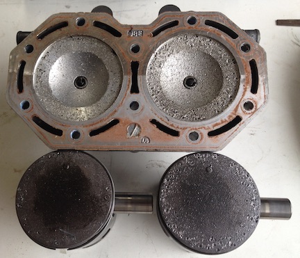
damaged head/pistons photo
Attachment 18727
Progress
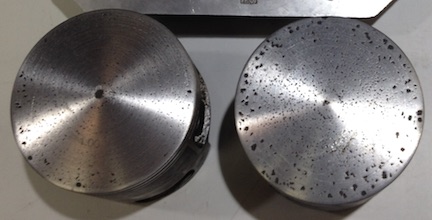
I was able to hone the cylinders so they are still within the specifications. I have worked on the pistons, they will clean up. I will need to balance them when I get finished with that. I will be able to account for the shorter pistons with a thinner base gasket for the cylinder or cutting the head.
pistons photo
Attachment 18729
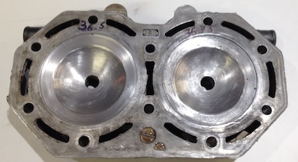
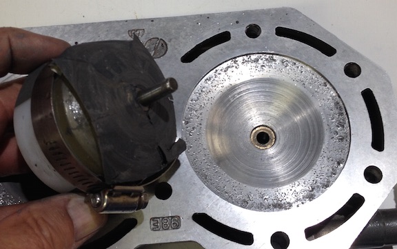
I am currently working on the head. Since the engine was previously rebuilt and I do not trust the rebuilder, I could not be sure the combustion chambers were the correct profile to begin with. I purchased another cylinder head with one good chamber, the other chamber was damaged by what I suspect was detonation. Possibly due to an air leak in the crankcase. I will also be able to repair this head to use on a spare engine I am also building
good chamber photo
Attachment 18730
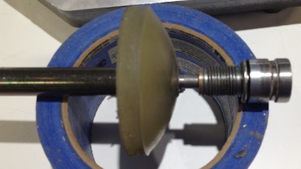
Making a form tool to fit the chamber.
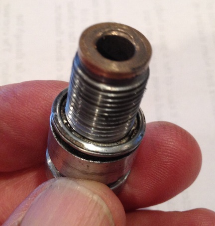
I polished and waxed the good chamber. Then removed the ceramic electrode from an old spark plug. Turned the ground electrode off the end. Then bored the plug to fit a bronze bushing inside.
Spark plug photo
Attachment 18731
Then I made a mandrel by cutting the head off a 1/2 bolt. Threaded 2 nuts on the end and jammed them tight against the shank of the bolt. The nuts give the resin something to grip to resist torque. Then turned the end of the bolt to fit the bushing I put in the spark plug. With the plug screwed into the head, I leveled the head so the resin will flow into the chamber level. Then inserted the mandrel into the bushing. Then mixed and poured polyurethane resin into the chamber to create a form tool with the correct shape.
form tool photo
Attachment 18732
The problem-
After the resin cured I was able to attach some sand paper to the form to remove the dings from the chamber. The process worked OK, but not great. I was quickly and easily able to remove the dings from the chamber. However it I am not able to get finer grades of paper to conform well enough to the shape of the tool. The little wrinkles in the paper causes grooves in the chamber. It needs to be smooth to prevent detonation.
chamber and tool photo
Attachment 18733
After I find a good way to finish the chamber I can use that technique to clean up the squish band. Then CC the head and cut the surface as required to bring it back into specification according to how the pistons and deck height come out.
I have tried valve grinding compound on the bare from tool, it might work, but I am not able to find various grit sizes here locally. If anyone has other suggestions for a better way to get the abrasive to fit the form tool
.I am listening.
Thanks,
John
combustion chamber finishing tool
Quote:
Originally Posted by
olderdan

Hi Hemmjo
Wow sure made a mess of that engine.
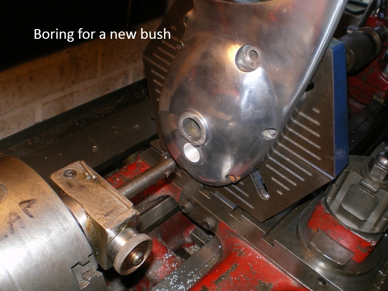
Unfortunately any form of purely circular lapping will always leave a grooved finish due to trapped debris and media, but you can certainly remove metal to a point. You could try gluing thin strips of emery radially to get over the wrinkling, that may help to give the debris somewhere to go, after that for me it would be down to hand finishing, a mirror finish is not necessary or even desirable, just smooth. Now I know what machinery you have, after finishing the chamber you could machine the squish band using an angle plate on the lathe crosslide and a boring head.
Attachment 18743
I have done more than a few jobs in this fashion using my drill table as a large angle plate.
The only problem I can see then is balancing the combustion chamber volume, you can do this using a measuring burette and paraffin but it takes a long time.
You seem determined so I am sure you will end up with a usable engine.
Just an idea for the resin,combustion chamber sanding tool.Eastwood(and others)sell loose grit for making buffing wheels.I'm not sure,but I think they sell the adhesive too.The idea is to spread the glue on the buffing wheel,then roll it in the grit of your choice and wait for it to dry.You could use the same principal,OR,the reverse.If you could think of a product to coat the combustion chamber that would lightly hold a layer of grit(say,hot wax?)then pour polyurethane in as you did before,grit would embed in the poly and wouldn't need glue?