Free 186 More Best Homemade Tools eBook:  
Get 2,000+ tool plans, full site access, and more.

User Tag List

Page 1 of 2 1 2 LastLast
Results 1 to 10 of 13

Thread: 20ft 14,000 lb trailer

  1. #1
    Supporting Member Frank S's Avatar
    Join Date
    Aug 2015
    Location
    Peacock TX
    Posts
    11,210
    Thanks
    1,982
    Thanked 8,784 Times in 4,206 Posts

    Frank S's Tools

    20ft 14,000 lb trailer

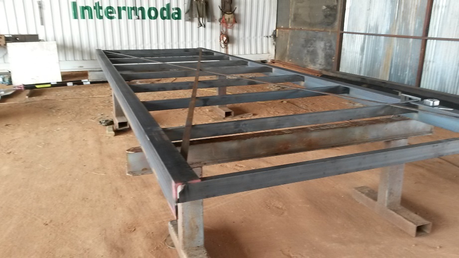
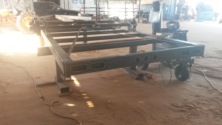
    My partner in a new venture we are entering into needed a trailer For the past few months I have been telling him we should just build one because he would never find a ready made trailer to suit him they would either be too heavy with things he didn't need or want or not have the capacity he wanted Finally after scouring 100's of trailer manufactures he agreed we should just build one. So I ordered a pair of 7,000 lb . axles with electric brakes on both a set of 6 leaf slipper springs 15,000 lb rated a 2 5/16" 15,000 lb rated coupler4 wheels rated for 105PSI tire pressure 5,000 lbs. and the steel to build the trailer. He searched and searched until he found USA made tires with a weight rating of 3640 lbs per tire
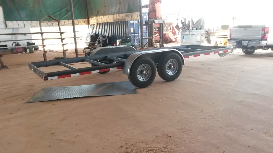
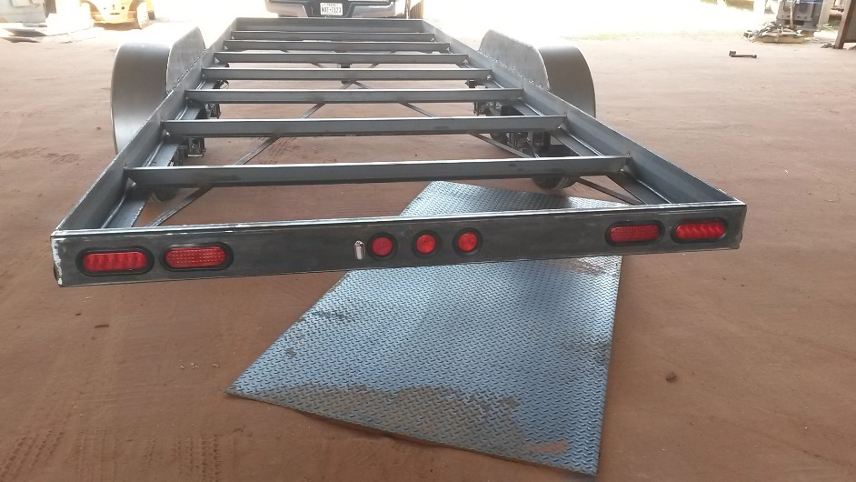
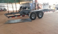
    This is what I built for him mostly while he filled a bunch of old tires with dirt for my retaining wall behind the shop.
    20ft 14,000 lb trailer-20210311_150937tl.jpg
    20ft 14,000 lb trailer-20210325_112510tr.jpg
    20ft 14,000 lb trailer-20210330_165716tr.jpg
    20ft 14,000 lb trailer-20210331_122212tr.jpg
    20ft 14,000 lb trailer-20210331_122227tr.jpg
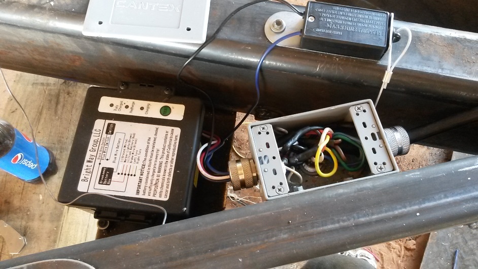
    For the wiring I ran a 7 conductor cord through the side beam of the tongue entering via a water proof electrical box where the front amber clearance lights and the breakaway battery is connected as well all connections are soldered and double wrapped in heat shrink tubing no wires are cut. the cable continues along the frame on the right hand side to the rear light bar bumper and continues across then up the left side to the front axle then the Positive and the ground wire are reversed back to the rear axle. All wiring connections for the rear lights are done inside the rear tube split twisted soldered and protected with 2 layers of heat shrink tubing every light is grounded to the white ground wire as well as grounded to the frame the lights are all LED

    186 More Best Homemade Tools eBook
    Never try to tell me it can't be done
    When I have to paint I use KBS products

  2. The Following 9 Users Say Thank You to Frank S For This Useful Post:

    baja (Apr 6, 2021), clydeman (Apr 5, 2021), IAMSatisfied (Apr 6, 2021), Jon (Apr 7, 2021), KustomsbyKent (Apr 5, 2021), mlcohen987 (May 10, 2021), NortonDommi (Apr 3, 2021), Rangi (Apr 5, 2021), Scotsman Hosie (Apr 6, 2021)

  3. #2
    Supporting Member NortonDommi's Avatar
    Join Date
    Jul 2014
    Location
    North Island, New Zealand.
    Posts
    990
    Thanks
    1,800
    Thanked 525 Times in 315 Posts

    NortonDommi's Tools
    Very nice especially the wiring. One of my pet hates is dodgy wiring - last time someone asked me to just check the trailer for a warrant of fitness, "I think it needs a bulb" ended up a complete rebuild, brakes, brake lines, coupler, tyres. many modifications, a new deck AND a rewire.
    One day I will learn aye.

    2000 Tool Plans

  4. #3
    Content Editor
    Supporting Member
    DIYer's Avatar
    Join Date
    Aug 2013
    Posts
    3,056
    Thanks
    772
    Thanked 1,852 Times in 1,653 Posts


    Thanks Frank S! We've added your Trailer to our Trailers and Towing category,
    as well as to your builder page: Frank S's Homemade Tools. Your receipt:


  5. #4
    Supporting Member Frank S's Avatar
    Join Date
    Aug 2015
    Location
    Peacock TX
    Posts
    11,210
    Thanks
    1,982
    Thanked 8,784 Times in 4,206 Posts

    Frank S's Tools
    Quote Originally Posted by NortonDommi View Post
    Very nice especially the wiring. One of my pet hates is dodgy wiring - last time someone asked me to just check the trailer for a warrant of fitness, "I think it needs a bulb" ended up a complete rebuild, brakes, brake lines, coupler, tyres. many modifications, a new deck AND a rewire.
    One day I will learn aye.
    My Partner asked me why I ran the wiring in the way that I did.
    For one thing 90% of all wiring problems seem to start with a faulty or failing ground and since every thing requires a ground this wire receives the heaviest current loading it also happens to be a ga. larger in diameter in most 7 conductor trailer cords. Obviously on a trailer with so few lights and being LED the amperage draw is minimal compared to a 53 ft semi trailer with dozens upon dozens of lights strung along the sides and rear. There is still no reason not to try and wire it the best way possible. I detest using crimp connectors when ever possible, even when I do use them I use the non insulated ones if I can get them or remove the plastic insulation so I can solder as well as crimp then insulate with heavy duty shrink tubing for a water proof connection. When making branch connections off of a main conductor I remove only enough insulation to be able to separate the strands then pass the branch wires through these then twist the tail of the branch wires half along one side of the split and half along the other side then fold the connection tightly so the shrink tubing will slip over it My reason for using a double layer is probably a bit anal but I feel it makes for a more factory molded looking connection. I also use only 3m or greenbrier brand tubing because it is thicker and makes for a more rubberized coating. My reasons for leaving the main cord continuous from beginning to end also insures there are no possibilities of a loose connection happening throughout the cord .
    Lastly once he decides on the color of the trailer and we paint it I will spray a Military grade coating inside all hidden cavities on the trailer I will be using the KBS cavity coater this is just one more defense against moisture intrusion.
    One thing I failed to mention the trailer currently weighs only 2200 lbs by the time I add ramps and the extruded aluminum runners for the floor and a nose guard to protect the grill and headlights of his pickup for when pulling it behind his Prevost's Motor coach it will still only weigh 2600 lbs or less leaving him with a trailer capable of hauling 11,400 lbs.
    Never try to tell me it can't be done
    When I have to paint I use KBS products

  6. The Following 4 Users Say Thank You to Frank S For This Useful Post:

    baja (Apr 6, 2021), EnginePaul (Apr 11, 2021), mlcohen987 (May 10, 2021), NortonDommi (Apr 4, 2021)

  7. #5
    Supporting Member NortonDommi's Avatar
    Join Date
    Jul 2014
    Location
    North Island, New Zealand.
    Posts
    990
    Thanks
    1,800
    Thanked 525 Times in 315 Posts

    NortonDommi's Tools
    That 90% fault rate sounds about right. Totally agree with the reasoning except the solder only because I questioned the ex-Air Force avionics guy who did the electronics on the fishing boats I used to work on why he didn't use solder and he explained why I should use top quality non-insulated crimp connections with top quality crimping tools.
    When done properly the crimp creates a molecular bond between wire and terminal which minimises voltage drop. Solder also creates a hard, ridged area at the cable/solder junction which will cause a break. I use liquid tape,(different colours are handy for keeping track of things and useful for bundling as a few spots hold wire together in a loom),and heat-shrink over the top, leaves the cable flexible right up to the terminal but with extra support i that area. Totally sealed except for the bit of terminal that is being connected and I use dielectric grease there. I have just assembled a self-powered wood chipper for a friend and cleaned up and relocated all the wiring plus added a lot more support around the engine bay. Thing does vibrate in use and there was a lot of potential for problems. Still got to change the lights and add a few more markers. Nice unit but came with crappy BULB lights! Had a good downpour overnight and when I took one off to measure for L.E.D. lights one already had water in it. Added another coolant temperature sensor in the bottom radiator tank as well as if a leak occurs the normal gauges read low right up until they peg from super-heated steam just before the engine seizes.
    I will have to look up the KBS cavity coater but probably can't get it here. I use a long wand of 6 mm PVC air tube with a homemade nozzle adapted to an underseal gun and spray a Tannin base rust converter followed by fish oil which seems to get into every tiny recess and seal things up good.
    Sounds like your friend will have a trouble free run with that beast you've built .

  8. #6
    Supporting Member Frank S's Avatar
    Join Date
    Aug 2015
    Location
    Peacock TX
    Posts
    11,210
    Thanks
    1,982
    Thanked 8,784 Times in 4,206 Posts

    Frank S's Tools
    My connections are solid mechanical with the branch wire passing through the main cables then a few strands are laced and twisted in one direction while the rest are done in the opposite direction this makes a T connection then the T is folded in on itself tightening the connection even further the solder is really unnecessary
    but I apply just enough so none of the strands can fray by using 2 layers of the shrink tubing the protective insulation extends well beyond the connection point and is thicker than the original wiring insulation this makes for a ridged but still flexible protective coating a ways away from the connection.
    The thing I don't like about crimp terminals (and even though I don't like them I still have about every size and configuration of them ever made), is you are introducing a dissimilar metal to the conductor which can create a resistance to current. crimp connectors are a crap shoot when it comes to crimping them too much crimp and you crush and weaken the wires too little crimp and the connection will not be sound all stranded wires are different some have very fine micro hair thicknesses while others of the same gage may have fewer than 1/3 the number of wires for a given gage and be much larger in diameter.
    I like using a 10x diameter rule when making connections then lacing and twisting this insures that every wire makes contact several times with the strands in the parent cable the solder is nothing more than a binder and has nothing to do with the actual connection. it it did I would use a copper to copper fusion method similar to spot welding, but the key factor there for making those connections last forever is to have a good thick insulation covering the connection for some distance beyond the connection.
    U sometimes will use the liquid tape on older wiring where the insulation has become cracked or scraped away then wrap over that with a high quality electrical tape that can be heated to melt it to itself.
    Dielectric grease is good but just like colas not all brands are the same. and it can be rubbed off even the Cavity coater may need to be re applied every few years
    A product by the name of LPS3 is a reasonable alternative to the cavity coater not the same exact formulation but as near to the same grade as anything else on the market
    Never try to tell me it can't be done
    When I have to paint I use KBS products

  9. #7
    Supporting Member NortonDommi's Avatar
    Join Date
    Jul 2014
    Location
    North Island, New Zealand.
    Posts
    990
    Thanks
    1,800
    Thanked 525 Times in 315 Posts

    NortonDommi's Tools
    I hear you on the connections, I was just repeating what a guy with over 20 years experience wiring fighter jets told me and showed me. Any solder creates an increase in resistance. Might be important in high-end super critical electronics but probably doesn't matter a jot in the world thee and me live in. We have a local firm called Utilux and they make a huge range of terminals. I buy the brass non-insulated ones. I tested some crimps years ago at Auckland Unitech where they test welds and with a good crimp you can see the melding of the Copper and the Brass after current has flowed through it, looks like a friction weld.
    I reckon crap connections, dirty connections and vibration are the worst enemies of the Blue Guys and generally find that just addressing those things stops problems.
    Had a friend years ago who used to build insanely fast bikes but they kept breaking down due to him twisting bits of wire together and wrapping with whatever was handy, insulation tape, sellotape, sticky plasters whatever.
    Well just happened one fine sunny Summer day a bunch of us were tootling down the motorway on the way to the classic races when Richard stood up on his pegs and started punching and whacking his groin!
    He veered across two lanes, across the ditch at an angle and up a bank while doing marvelous stunt riding! Up he went, up, up and SMACK into the wooden fence at the top. Tumbling down he came while we all stopped and ran over to see what had happened.
    As we got close to his bike we saw it was on fire. Turns out that he had been in a hurry to get his bike together and hadn't tightened up the fuel line, a small leak had developed and wind had blown this into his crotch were it puddled, one of his famous bits of sticky tape had come off and the bare wire banged against the frame.
    What are the odds that a small spark could ignite fuel on a motorcycle at 60-70 MPH?

    He got serious about his wiring after that.

  10. #8
    Supporting Member Frank S's Avatar
    Join Date
    Aug 2015
    Location
    Peacock TX
    Posts
    11,210
    Thanks
    1,982
    Thanked 8,784 Times in 4,206 Posts

    Frank S's Tools
    Agreed dodgy wiring has been the ruination of many a projects. poor insulation practices maybe even more so.
    I have a group of friends who build a wide range of home made wind turbines while making their coils for the generators they pot them in resin. Their connections are done in a telegraph lineman's fashion tightly twisted then brass sleeves slid over them and crimped. then insulated with that liquid rubber stuff that you can buy to dip the handles of your pliers in to form a thick insulated grip.
    I learned a long time ago that the most important part of making a connection was to first make a strong mechanical connection before using any holding medium be it solder or metal crimping then insulate to prevent any humidity from being able to cause corrosion.
    Once I was making up a string of battery cables for a bank of batteries I had crimped the terminal lugs on the ends of the 350 MCM cables with a hydraulic crimper but didn't coat with any form of insulation just used liberal amounts of dielectric grease on them. Due to the out gassing that happens during charging cycles it wasn't long before I had corrosion issues to deal with on a monthly basis during the winter months. I finally got everything cleaned up nice and bright then poured rubber over all of the terminals that stopped the problem
    Never try to tell me it can't be done
    When I have to paint I use KBS products

  11. #9
    Supporting Member IAMSatisfied's Avatar
    Join Date
    Apr 2017
    Location
    The desolate ranch country of Northeastern corner of New Mexico, USA
    Posts
    394
    Thanks
    269
    Thanked 236 Times in 125 Posts

    IAMSatisfied's Tools
    Frank, you had me at "...every light is grounded to the white ground wire as well as grounded to the frame... "... I like the way you think.

  12. #10
    Supporting Member Frank S's Avatar
    Join Date
    Aug 2015
    Location
    Peacock TX
    Posts
    11,210
    Thanks
    1,982
    Thanked 8,784 Times in 4,206 Posts

    Frank S's Tools
    Quote Originally Posted by IAMSatisfied View Post
    Frank, you had me at "...every light is grounded to the white ground wire as well as grounded to the frame... "... I like the way you think.
    Well the white wire on the pigtails had an eyelet already crimped to them so why not take advantage of it. when I made the connections I did so in a way that allowed the eyelet to be utilized. This not only serves to allow the white ground wire to share the grounding load with the trailer frame and at the same time almost guarantees there should never be a grounding issue. Since the electric brakes also use the white ground wire if none of the lights or the white wire were grounded to the frame during braking the lights could dim or the brakes not receive sufficient current to assist in stopping.
    I've seen a lot of smaller trailer at night that only had the 4 wire conductor and no ground wire at all these rely on the ground being transmitted through the coupler and ball often times when following them on a rough road the lights would wink at me going on and off or dimming than becoming bright again A sure fire recipe for a failed or burned out light, especially incandescent lamps as they like to be left on LEDs suffer their own demise due to varying voltage and current
    Never try to tell me it can't be done
    When I have to paint I use KBS products

Thread Information

Users Browsing this Thread

There are currently 1 users browsing this thread. (0 members and 1 guests)

Bookmarks

Posting Permissions

  • You may not post new threads
  • You may not post replies
  • You may not post attachments
  • You may not edit your posts
  •