Attachment 35939
.
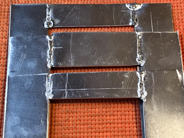
Set up a couple of digital generators to my old analogue TIG welder this spring, in an attempt to optimize its wave forms of welding current, to help my self when I make some butt-welding to thinner aluminium sheets.
Printable View
Attachment 35939
.
Set up a couple of digital generators to my old analogue TIG welder this spring, in an attempt to optimize its wave forms of welding current, to help my self when I make some butt-welding to thinner aluminium sheets.
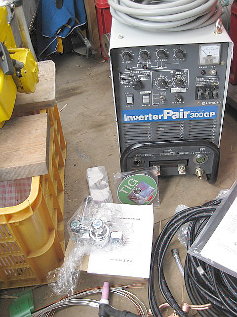
Here showing my old TIG welder;
Attachment 35940
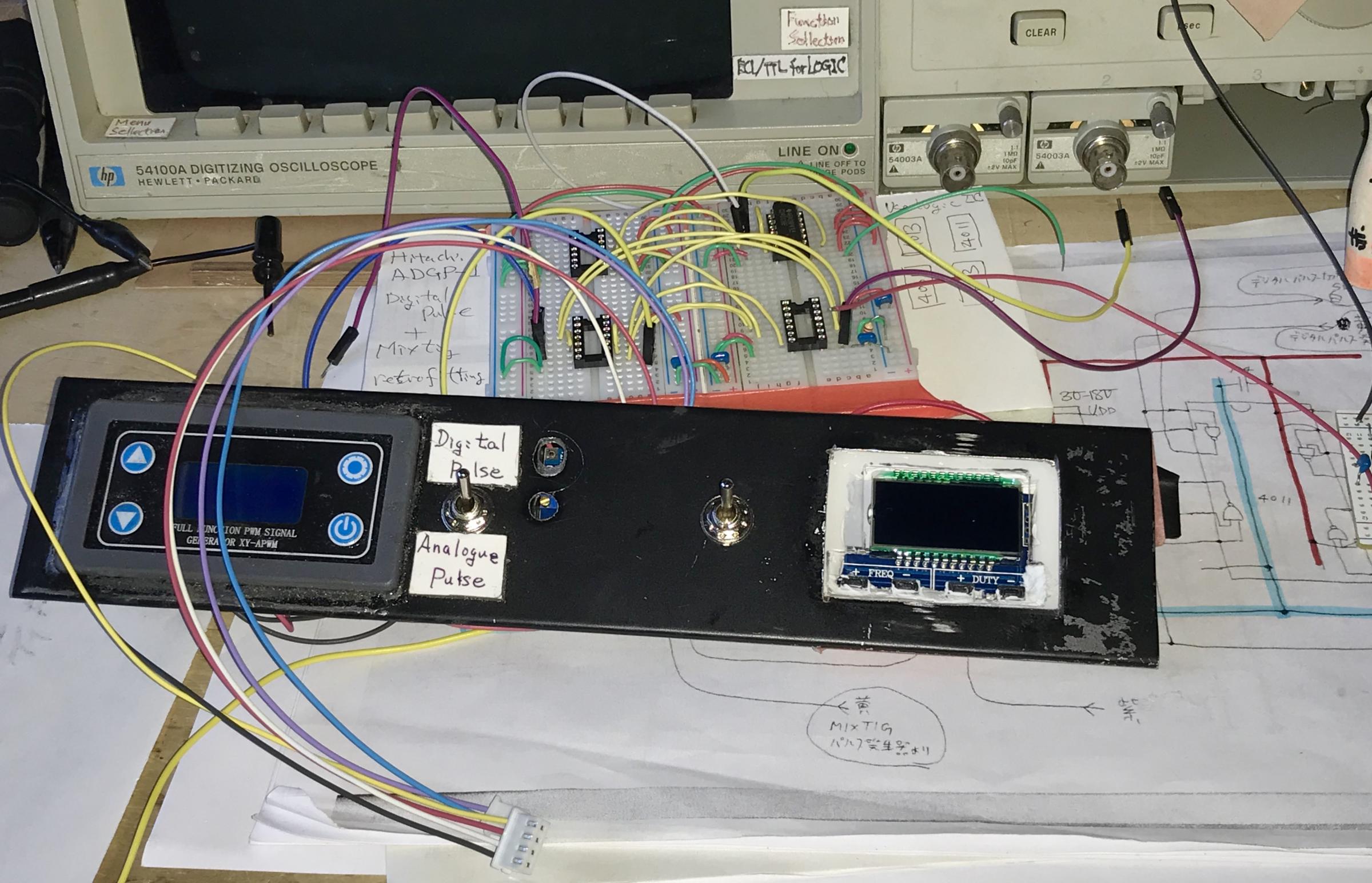
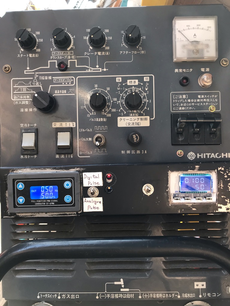
The digital unit above is set up on the front panel;
Attachment 35941
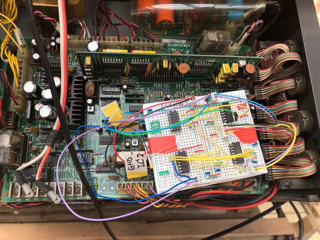
Several logic-chips are placed on a small additional board, and is placed on the main circuit board of the welder;
Attachment 35942
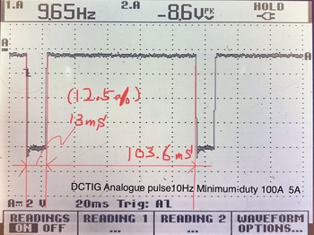
The default setting only provides the minimum duty ratio of welding pulse as 12.5%
.
Attachment 35943
.
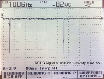
but I wanted smaller duty as small as down to 1.0% for each welding pulse frequency,
showing one sample I got after this retrofit;
.
Attachment 35944
This old welder has a pulse-range from nearly 0.5Hz up to 500Hz done by analogue frequency generator by default. This old set-up of analogue pulse is not replaced with the new, it can be used if I want.
One of the features I love is that this new set-up can provide higher pulse frequency from 500Hz up to 900Hz, which I found useful in welding thinner steel sheet.
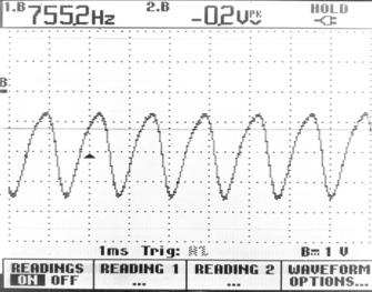
The arc sometimes wonders when the welding amperage is set low, like 30A for welding current and 5A for base current.
But I feel like this problem has nearly gone since I added this new digital generator by applying DC welding pulse frequency higher than 750Hz;
.
Attachment 35945
.
with this frequency the arc shows somewhat better stability to the aimed point.
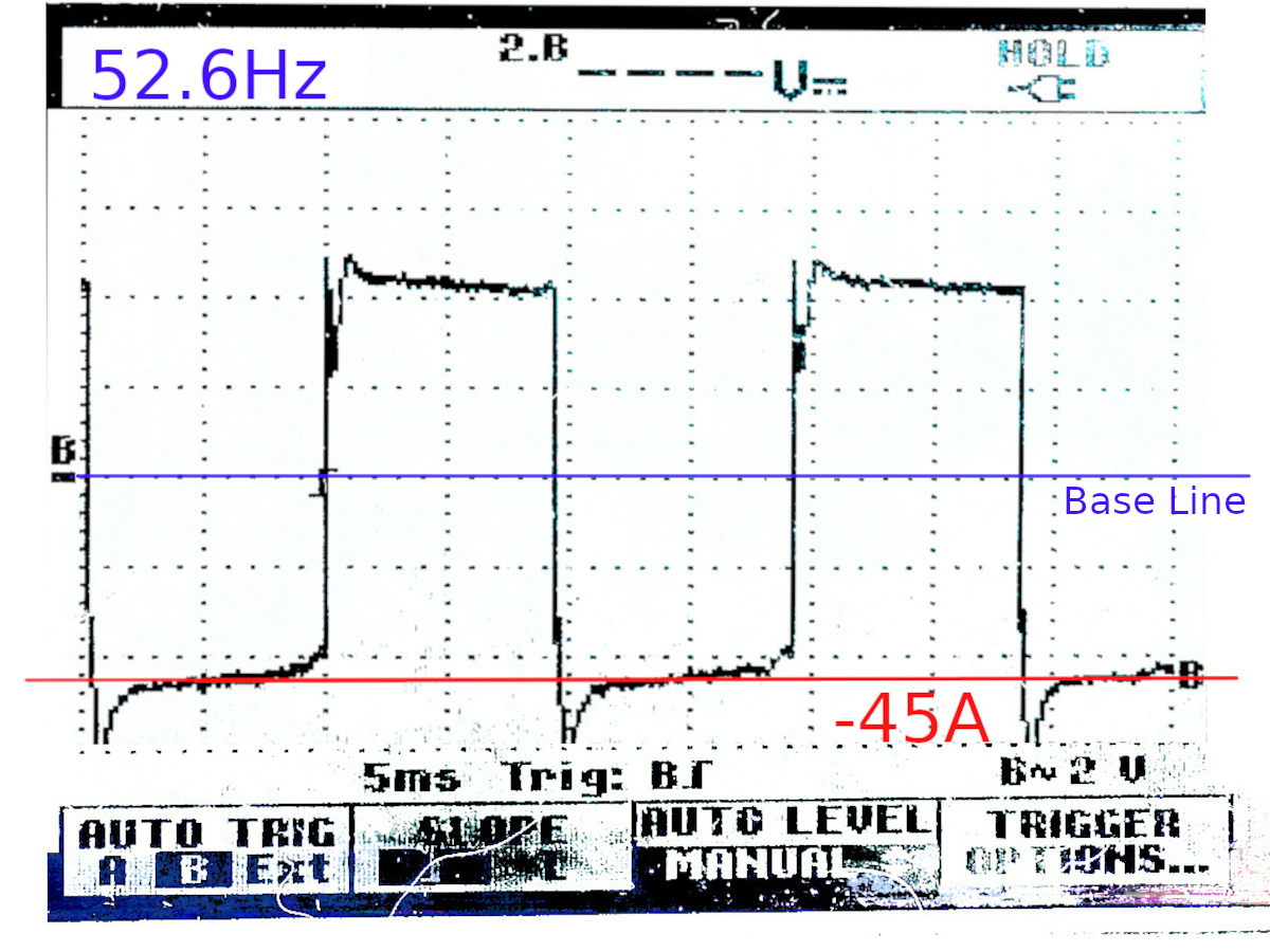
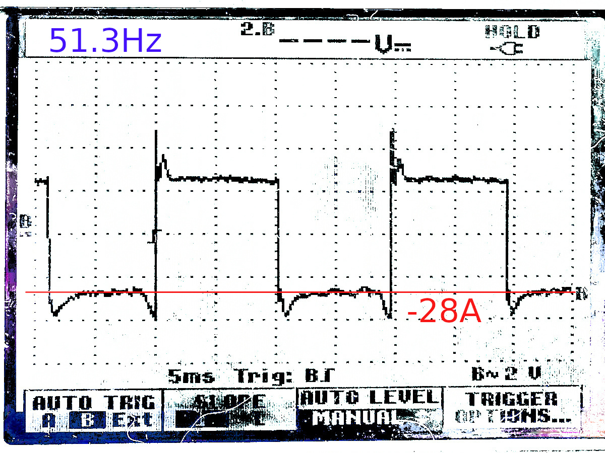
Below is a default wave form of Alternative Current welding, aluminium for example, showing the minus peak as 45A besides overshoot.
Output power is set to 50A for welding;
Attachment 35947
This shows the real welding power is a tad lower than the setting value.
Here is another wave form attained with the same setting but the output power was set to 30A;
Attachment 35948
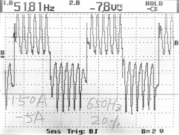
Now I'm going to replace the rectangular wave forms of the both sides (of plus and minus domains), with a couple of pulses of arbitrary frequencies given by this new addition;
Attachment 35949
Replaced the rectangular wave with 650Hz pulses, setting power 150A for welding.
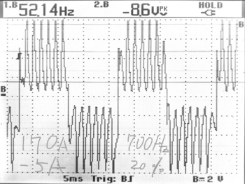
Attachment 35951
also with 700Hz pulses, setting power 170A.
<!-- BEGIN /var/www/html/homemadetools/protected/modules/zeus/views/tool/postUpdate.php -->
Thanks chy_farm! We've added your Digital Generators for a Welding Machine to our Metalworking category,
as well as to your builder page: chy_farm's Homemade Tools. Your receipt:
<div id="blocks"> <div class="block b1 pngfix"> <div class="bimg"> <div> <a href="https://www.homemadetools.net/homemade-digital-generators-for-a-welding-machine-2"> <img src="/uploads/234725/homemade-digital-generators-for-a-welding-machine.jpeg"/> </a> </div> </div> <div class="head pngfix"></div> <div class="left pngfix"></div> <div class="right pngfix"></div> <div class="blockover b1 pngfix"> <div class="title"> <a href="https://www.homemadetools.net/homemade-digital-generators-for-a-welding-machine-2">Digital Generators for a Welding Machine</a> <span> by <a href="https://www.homemadetools.net/builder/chy_farm">chy_farm</a></span> </div> <div class="tags">tags: <a href='https://www.homemadetools.net/tag/welder'>welder</a>, <a href='https://www.homemadetools.net/tag/electronics'>electronics</a> </div> </div> </div> </div>
<!-- END /var/www/html/homemadetools/protected/modules/zeus/views/tool/postUpdate.php -->
As far the schematic, I am thinking of asking a buddy who guides me to attain this job with a lot of information on welding machines if he gives me permission to open his schematic design of this unit.
A nice addition to your old welder. A You have indeed created a much easier to use welder for thinner materials. How does the overshoot work? I'm guessing that your initial arc will be a little bit easier to strike with your settings.
Hi mwmkravchenko, shame but I yet did not think of the overshoot. Thank you for your comment. I am glad to hear something informative from you on this if you do not mind.
Chy
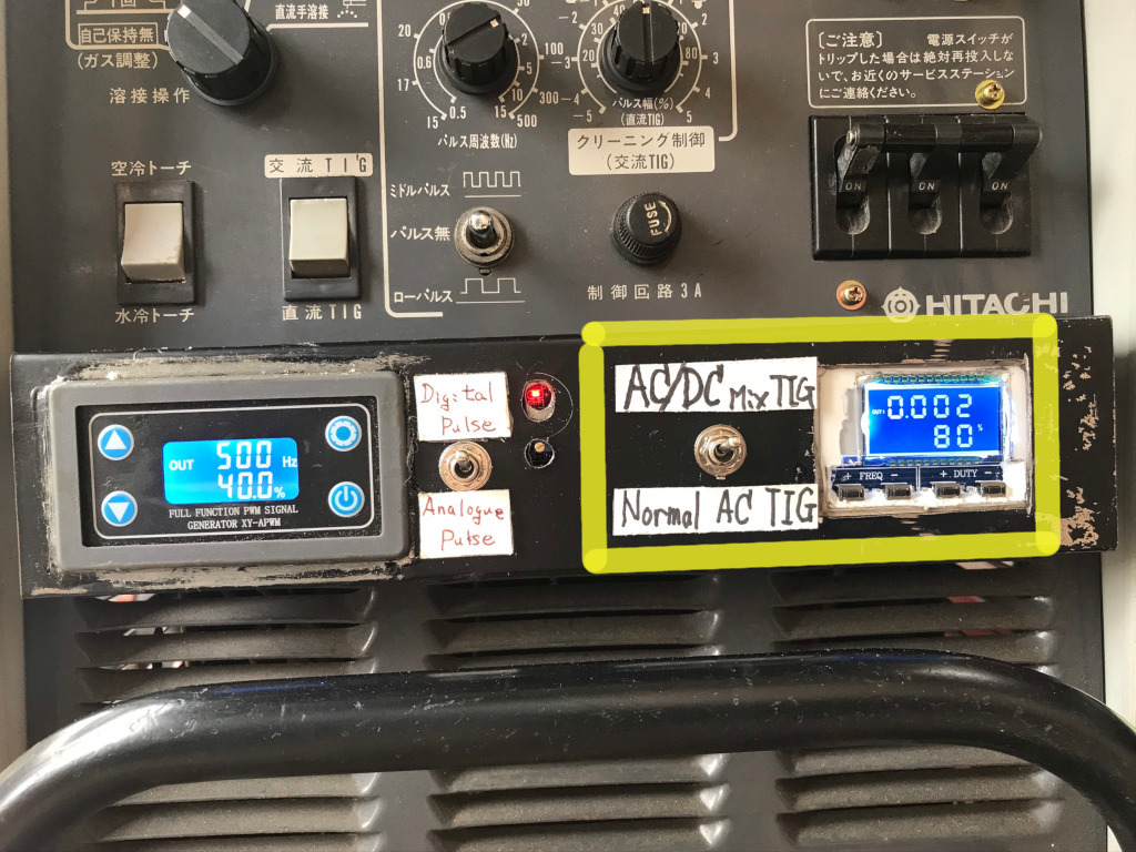
One more feature I love about this new generator is that this can replace arbitrary legth of AC welding current with DC welding current.
This method is named "MIX TIG" by a domestic manufacturer Panasonic.Co. to their TIG welders.
My old machine is of mid 90's so is actually an older type built by Hitachi Co., which did not have this tool.
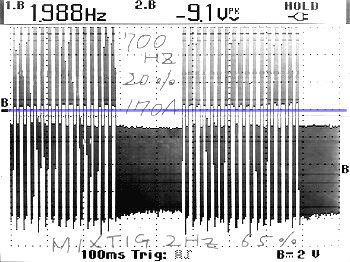
Attachment 35981
Above monitor in the right with yellow marking is for this "MIX TIG" method, showing it generates 2Hz frequency with 80% duty, for AC welding current, so this means 20% is for DC welding current.
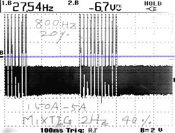
Showing a "MIX TIG" wave form of a couple of another setting, 2Hz frequency with 65% duty, 2Hz frequency with 40% duty, either for AC welding, as follows;
Attachment 35984
Attachment 35985
Chy
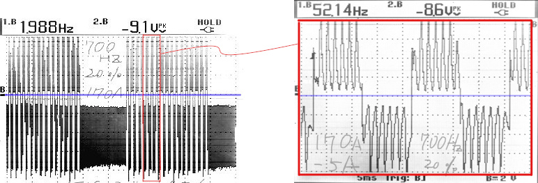
The former wave form I posted above can be illustrated in another way like one below;
Attachment 35986
Large red rectangle in the right is an enlarged view of the small red rectangle marked in the left. This part shows how the AC welding current with 700Hz pulse runs.
Chy
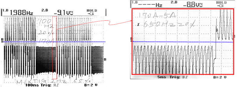
Again a large red rectangle in the right is an enlarged view of the small red rectangle marked in the left, but this is not of AC current.
Attachment 35987
Frequencies of the pulses of the two are a tad different, 700Hz for the left, 650Hz for the right. I did not monitored an enlarged view for 700Hz so instead used another but nearly the same view of 650Hz in the place of the true one.
This enlarged part shows how the DC welding current with 650Hz pulse runs.
Chy
What I see is a very useful add on circuit. I have no real comments to improve the waveform. If you want to tune the overshoot, generally it is a change in capacitance that will make the most effective difference.
My guess is that is practical use it will have no bad effects on the usefulness of the added functions that you have created for your welder.
Good morning mwmkravchenko, will keep your information in mind, thanks.
Chy
This buddy gave me OK to open his schematics on this project, will compile a bit and post here soon.Quote:
Originally Posted by chy_farm
(Note he says the schematics are only for Hitachi's welder, version name 'ADGP' and some series after this. )
Another great project. Well done. I love hacking old things to make them better.
When I was in high school I bought my first welder. There were two options when I bought it. I could have the 70 amp welder, or for more money (that I didn't have) I could buy the 90 amp welder. I bought the 70 amp. The 70 amp and 90 amp looked identical in the store. After using it for a while I noticed a different set of screw holes on the bottom of the machine. I noticed that the isolation plate between the primary and secondary on the transformer wouldn't come out all the way. All that needed to be done to gain the extra 20 amps was unscrewing the transformer, moving it over to the other screw holes, and putting it back together. It was a 30 minute job.
Your welder hack is obviously way more impressive. Keep up the good work and thank you for sharing. You should consider putting up a Github page.
Good morning Nova, thanks. I'v been thinking of Github too, where I have an account too.Quote:
Originally Posted by nova_robotics
This welding thing happened to you is funny, you did a good job!
Chy
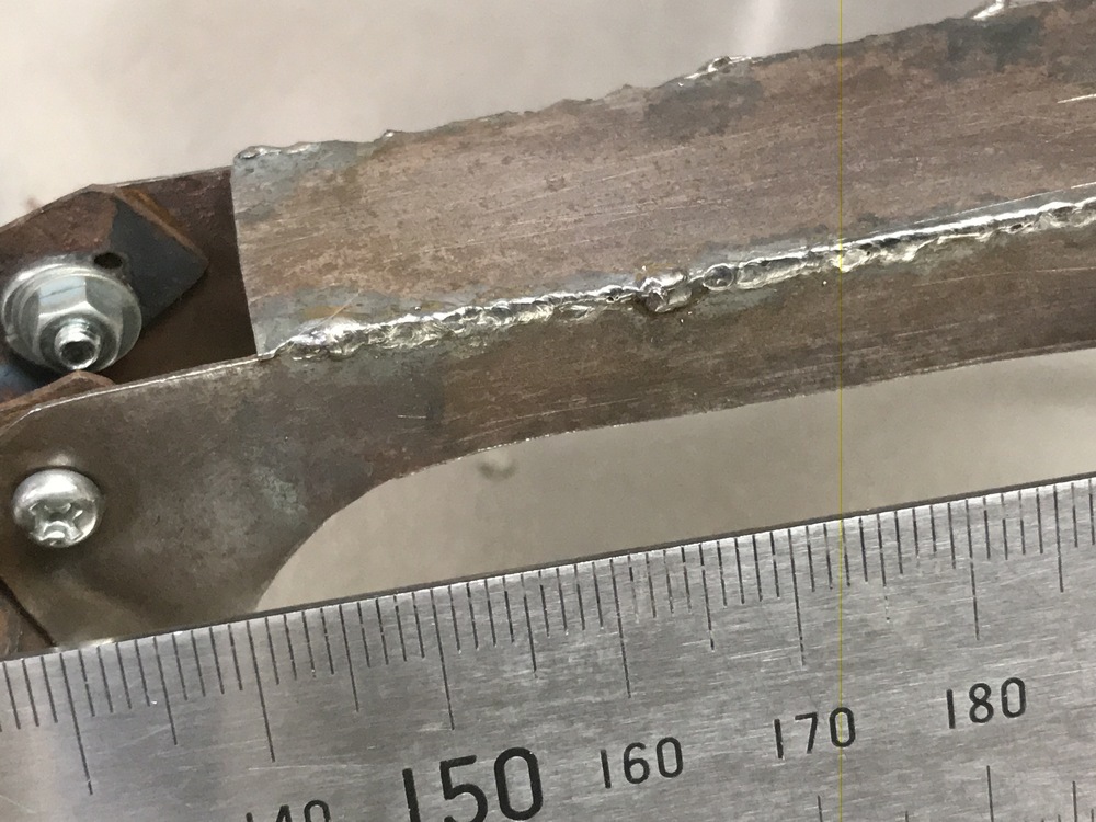
A result of this retrofit, tried angle-butt-welding with 0.5mm steel sheets by using 800Hz pulse, with setting of welding current 100A, base current 5A.
Attachment 36060
I think I did it better than ever as a green hand.
Good feature to me is that the arc does not wonder, may be because both the welding current and pulse frequency are high.
Chy
Making your welder a much more useful tool. What an improvement!
Good Sunday afternoon mwmkravhenko, glad you like it more!:hattip:Quote:
Originally Posted by mwmkravchenko
Chy
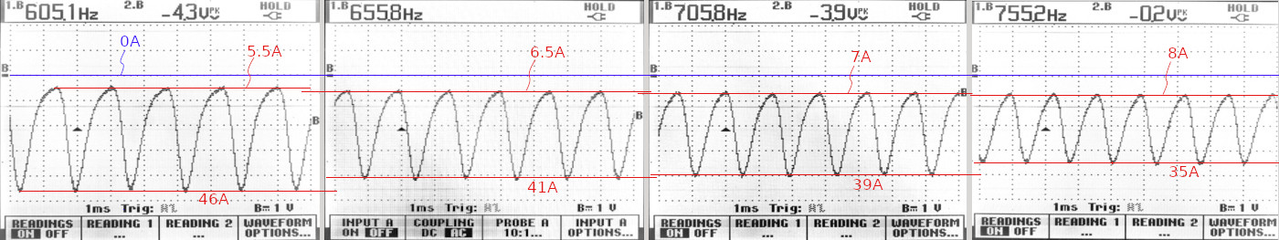
This data-comparison helps us to determine what the current should be and what the frequency of the pulse, especially for welding thinner steel sheets with butt-welding.
The setting welding current is 100A, base current 5A.
Attachment 36061
In my opinion, up to 900Hz from 500Hz, the higher the frequency of the pulse the easier the control of the arc.
This comparison tells we can raise the welding current safely in higher frequency, since the actual peak welding current does not go up too big for thinner sheet.
Chy
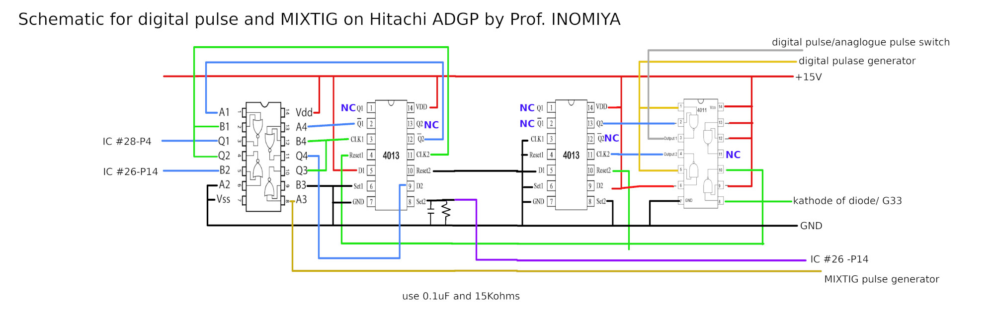
Attachment 36289Quote:
Originally Posted by chy_farm
This schematic is just for Hitachi's TIG welder, ADGP series. Hope you can apply this for yours thanks.
Chy
Long time since I had to deal with pulse generators like that. Something to watch out for is newer parts switch a LOT faster than the originals, can break the circuit.
Take it easy mate, the generator-band to be applied to this old welder is not so high, only 0Hz to at maximum not over 1kHz, they dont do any harm to the primary inverter board.Quote:
Originally Posted by jdurand
Chy
I just wanted to warn that trying to duplicate an old circuit with modern chips can lead to unexpected problems. If you don't know about the speed change it can be very confusing to you. I had to go through some old product designs done by another engineer and replace all the circuits like the above with stable ones. Where possible I used digital timing so it's exactly the same every time, but at least using parts with known Schmidt trigger inputs or analog parts makes one happier at the end of the day.Quote:
Originally Posted by chy_farm
Because of that same issue, I started adding an extra resistor to all my crystal oscillator circuits. The old design started randomly jumping to third overtone which isn't at all what was intended.
I know a little about it so this is not my case though.Quote:
Originally Posted by jdurand
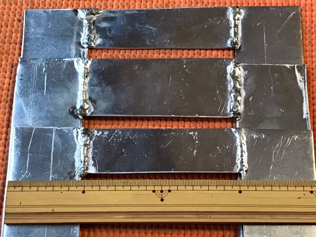
Attachment 36293
Attachment 36294
Setting means a lot to this retrofit-unit, for this MIXTIG setting better use 70% to 80% alternative current wave, and 30% to 20% dirrect current especially for thinner aluminium like above case, 1.5mm thick.
Several hits and errors made me get information of better setting.
Hope you can do it better than these above!
Chy