
 LinkBack URL
 About LinkBacks


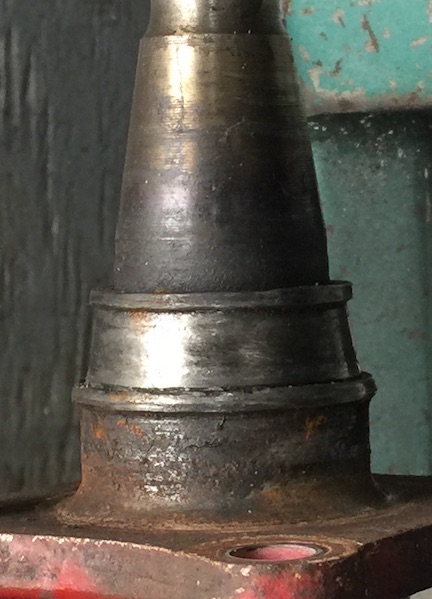
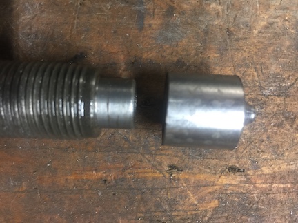
I had a bearing failure on a trailer which which damaged the hub (Trailer Wheel Hub Repair)
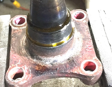
and left the cone stuck on the spindle.
I had an idea I might be able to cut the cone off with a carbide insert.
Not a good idea, but, you live and learn.
My bearing puller does not have enough reach for this job. Even if it did reach,
I am not confident it would be able to grip the rounded edges of the cone.
I do not have a bearing splitter. Every time think I might really need
to get one, I find another solution.
I still have the main bar of a puller I made almost 60 years ago in high school.
The screw and fingers have long been converted into something else. I do not
even remember what. I have been using the heavy steel bar with the magnetic
base for my Dial Indicator
I tuned a new 3/4-16 screw from some 7/8 hex bar. This one turned out better
than the one made from 1 square in high school. The new one also has a removable
end cap to protect the screw threads and whatever shaft it is using on.
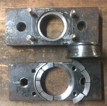
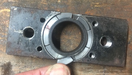
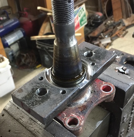
To grip the bearing cone a base plate is bored to just slip over the cone. A recess cut in
the plate allows retaining segments to slip under the bearing lip and prevents them from
being pushed out. The large hole in the base makes it too weak to apply much force without
bending. A top plate is bored to just fit over the spindle and drilled to bolt to the base.
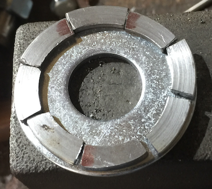
The retaining segments were made from a washer. It was first bored just large enough
to allow my 3 jaw chuck to hold it internally to turned the OD to fit the base groove and
faced to proper thickness to fit snug under the cone lip. Then held on the OD to bore
the ID to fit snug under the cone lip. That ring was then segmented on the bandsaw.
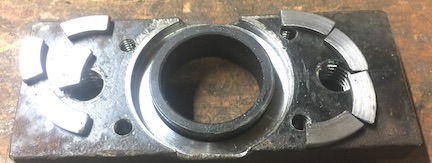
The base fits over the cone. Shown here after being removed
from the spindle for clarity
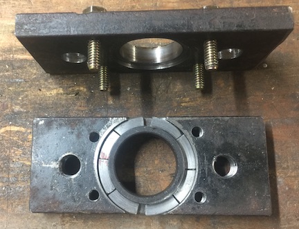
The retaining segments slide into slots on the side of the
base and fit snug under the cone lip.
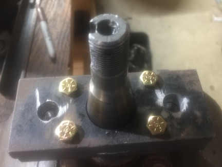
The top reinforcing plate bolts over the base. The holes were match drilled.
The base is tapped for both the small bolts and the large pulling bolts.
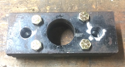
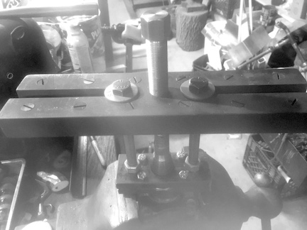
In use the puller bolts are threaded into the base until nuts tighten down onto
the reinforcing plate. This makes the plate assembly more rigid to reduce the
bending force at the center where the plates are the weakest.
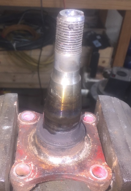
The spindle had been soaking with some PB blaster
The base plate over the cone.
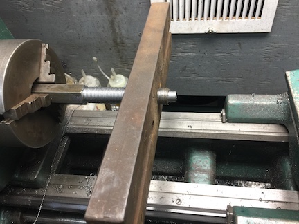
After sliding the segment into the slot, the reinforcing plate is bolted on.
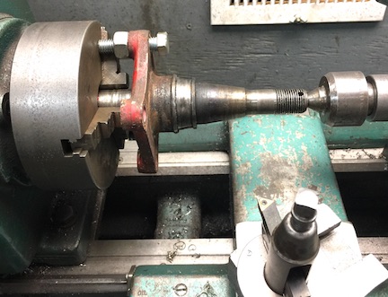
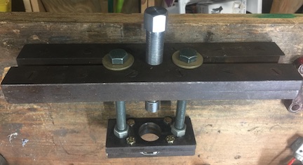
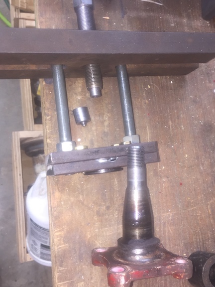
The puller bolted in place ready for the pull.
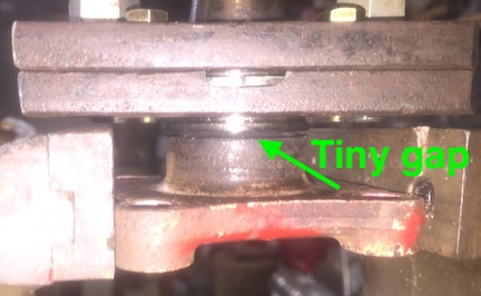
It took a bit to torque, but eventually I heard a POP sound. You can never
be sure at first what made that sound. Peeking under showed a tiny gap forming.
After the initial pop, it was not difficult to pull it off the rest of the way.
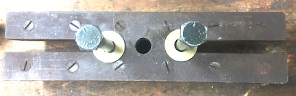
The puller and parts
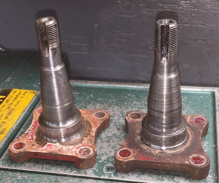
The cleaned up spindles. Waiting for speedi-sleeves for the seal surfaces.


 Reply With Quote

Bookmarks