
 LinkBack URL
 About LinkBacks


This covers the build and use of a device I built to help me in the shed. I hope it helps some of you. I live in a metric country, so the units are metric unless specifically mentioned otherwise.
The problem I am trying to solve getting older and weaker (either via age, or by trying to work smarter)
Since I dont have an easy solution for that problem, I figure I can design and build something to reduce the impacts.
One of those impacts is lifting heavy things, such as chucks on to the spindle of the lathe, or lifting a vice or universal dividing head on to the table of a milling machines, etc.
The tasks Ive mentioned above would require a crane with very fine levels of adjustment on the crane hook, especially when handling a chuck on to the threaded spindle of my big lathe.
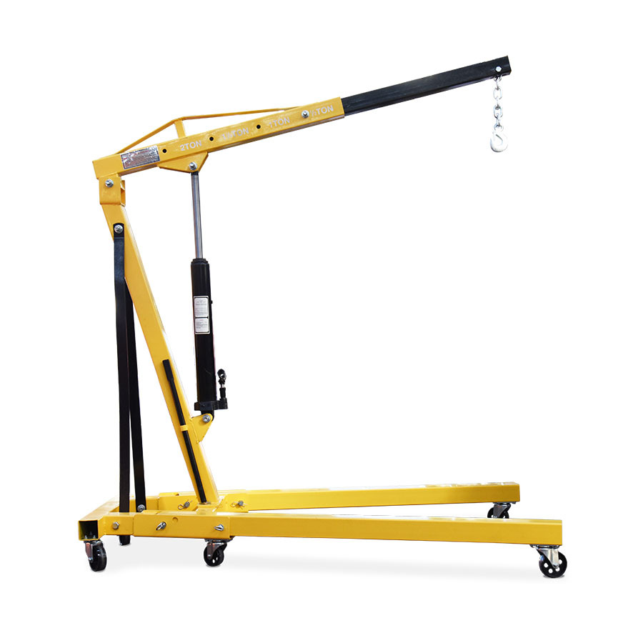
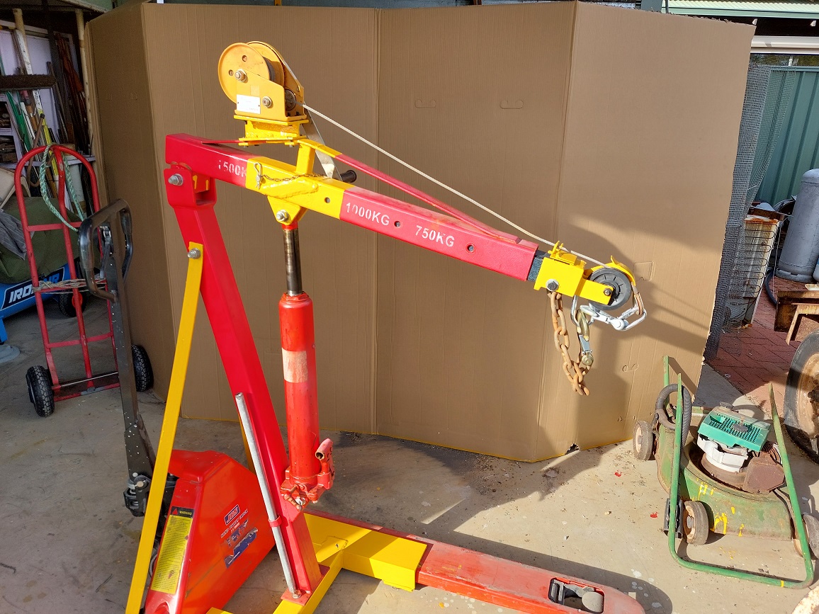
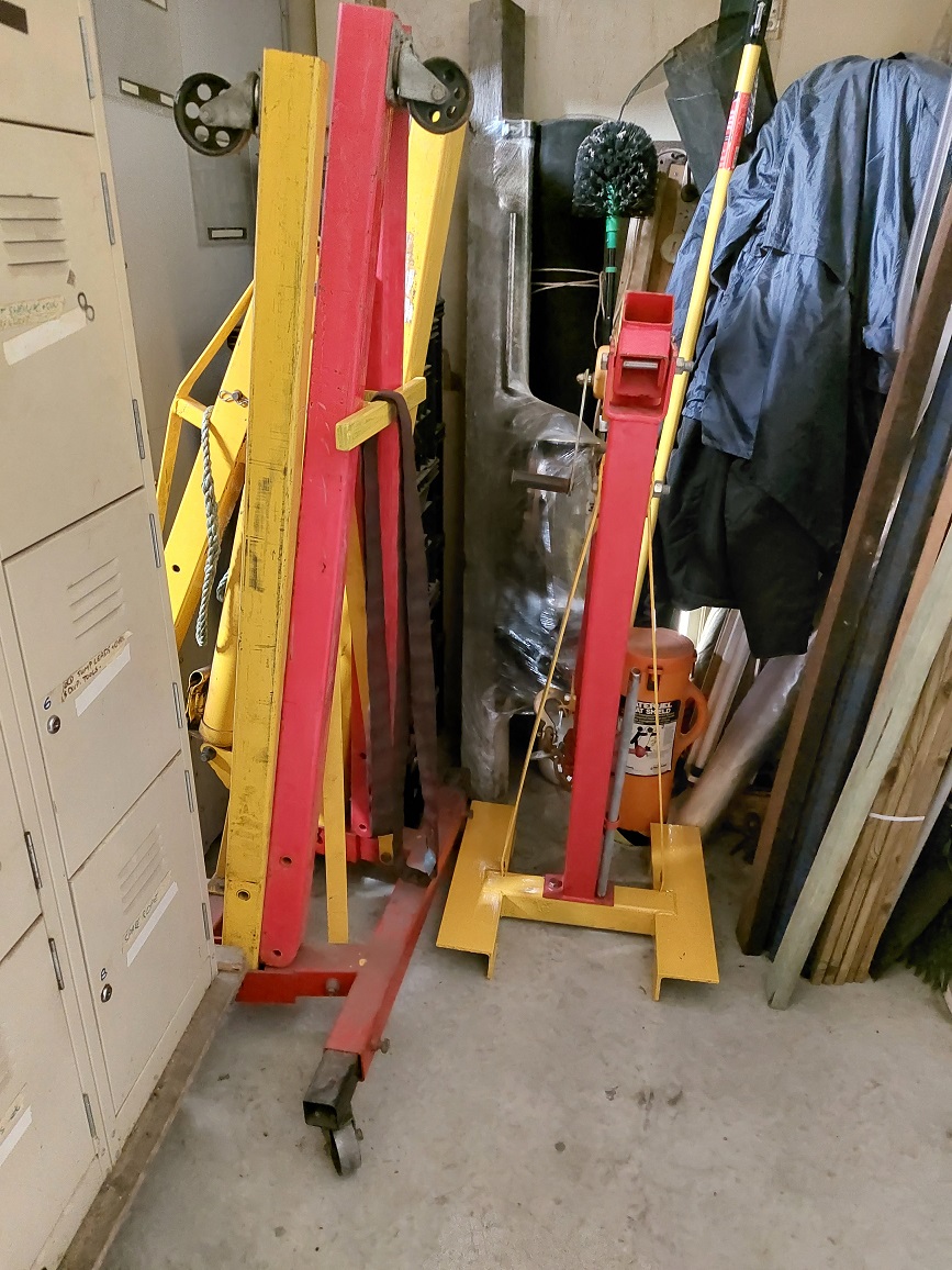
I already have an engine crane, and it is quite capable of lifting weights exceeding 2T, and it has limited mobility when something is on the hook due to the large footprint of the fold out legs, and the small diameter steel castor wheels do not lend themselves to fine movement when under load. An example engine crane is shown in photo 1.
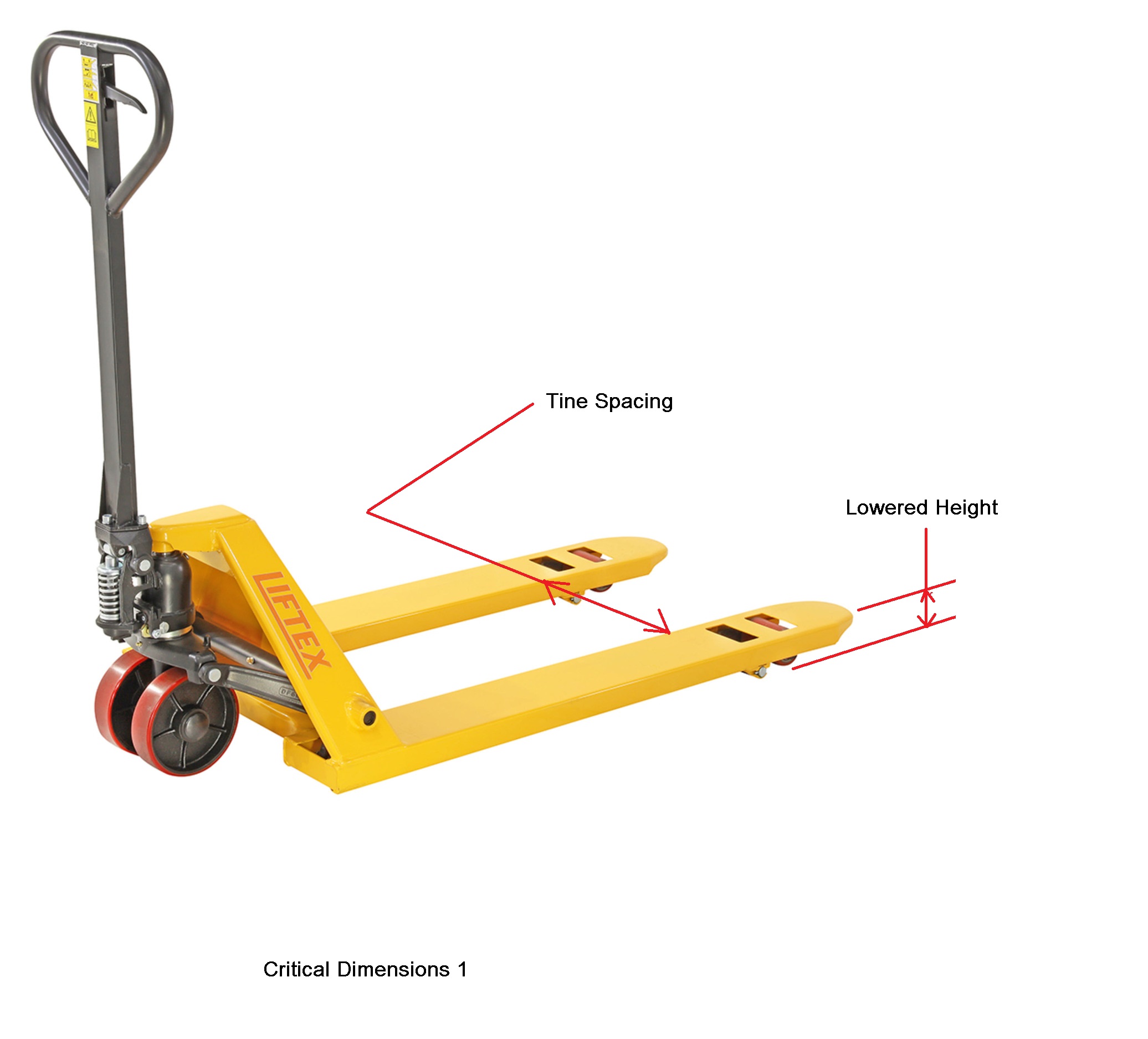
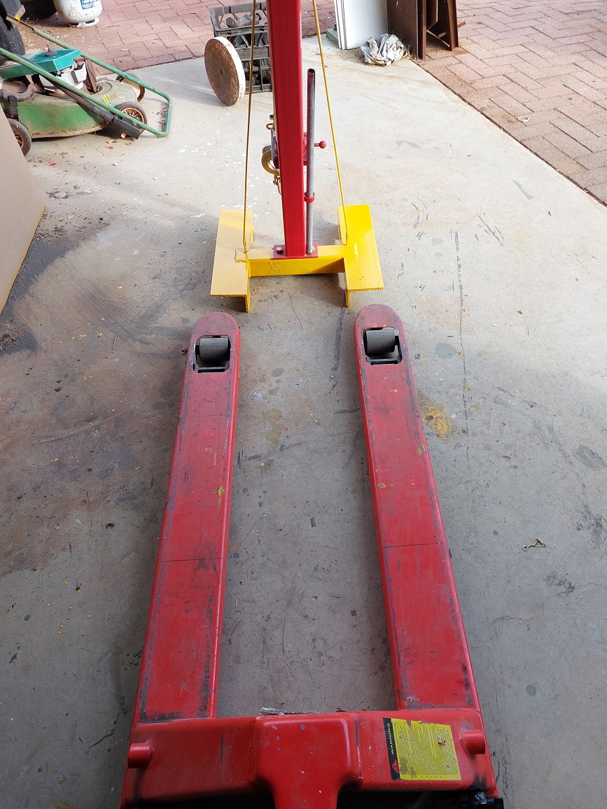
I already have a pallet jack in my shed, and a number of my benches, my big lathe, and my big milling machine are able to be moved with a standard 2.5T pallet jack. One thing pallet jacks are designed for is their maneuverability even when fully loaded.
Some years ago I saw a webpage where someone had grafted the mast and jib of an engine crane to the shortened base of a pallet jack to create a maneuverable crane, and it looked like a good marriage of the benefits of both machines, but it had some limitations. One of the biggest limitations was the modification was a permanent modification which prevented the pallet jack from being fully utilised in its original purpose.
My design is to make the incorporation of the crane to the pallet jack as a temporary attachment which can be added or removed with minimal effort, and no modifications which impact on the original utilisation of the pallet jack. This design not only retains the functionality of the pallet jack, but also allows the crane to be stored with a minimum footprint of valuable shed floorspace.
My design also includes a small winch as an auxiliary lifting point, this has use for items less than 500kg, and at maximum jib extension. You could consider the addition of the winch as optional, but I include it in the description so you know how to add it if you wish.
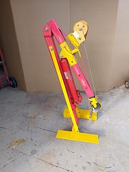
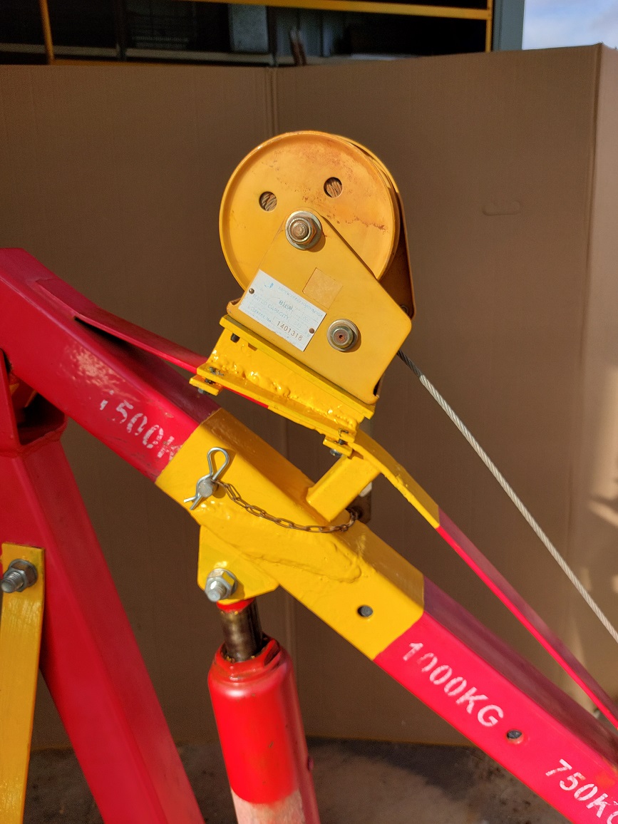
Step one obtain a pallet jack, and an engine crane. My engine crane was a damaged one found in a garage sale for a very modest sum, and as mentioned, I already have a pallet jack which a number of shed items were designed around. I repaired the damage to the engine crane, and obtained a 500 kg winch which will be incorporated into the design. I salvaged a few pulley sheaves from wrecked exercise machines, and purchased a clevis hook to suit the winch cable.
Step two measure some critical dimensions. Whilst both pallet jacks and engine cranes are fairly standard, there are often subtle differences in design and materials. ALL of the dimensions given in this article are based on the equipment I have, and I will explain where those critical dimensions are used so you can determine what the equivalent adjustments would be on yours.
Some critical dimensions are need to ensure pieces will fit together these include;
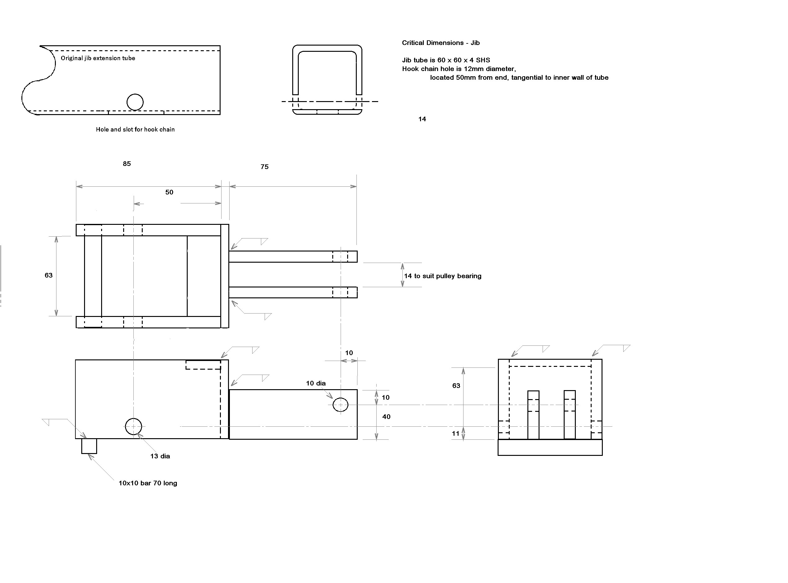
the dimensions of the end of the jib (material size, and size/ location of the hole which secures the short hook chain often fitted),
the mount for the mast to the base (hole size and centre to centre distance),
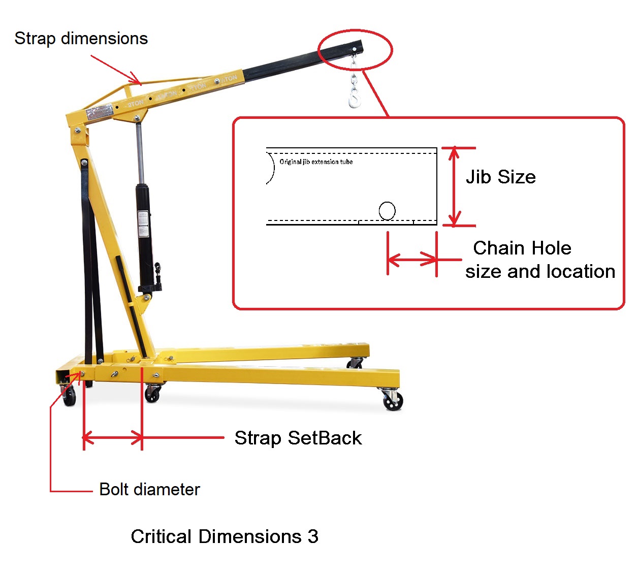
the dimensions of the top strap on the jib sleeve,
the hole size of the crane straps at the base connection,
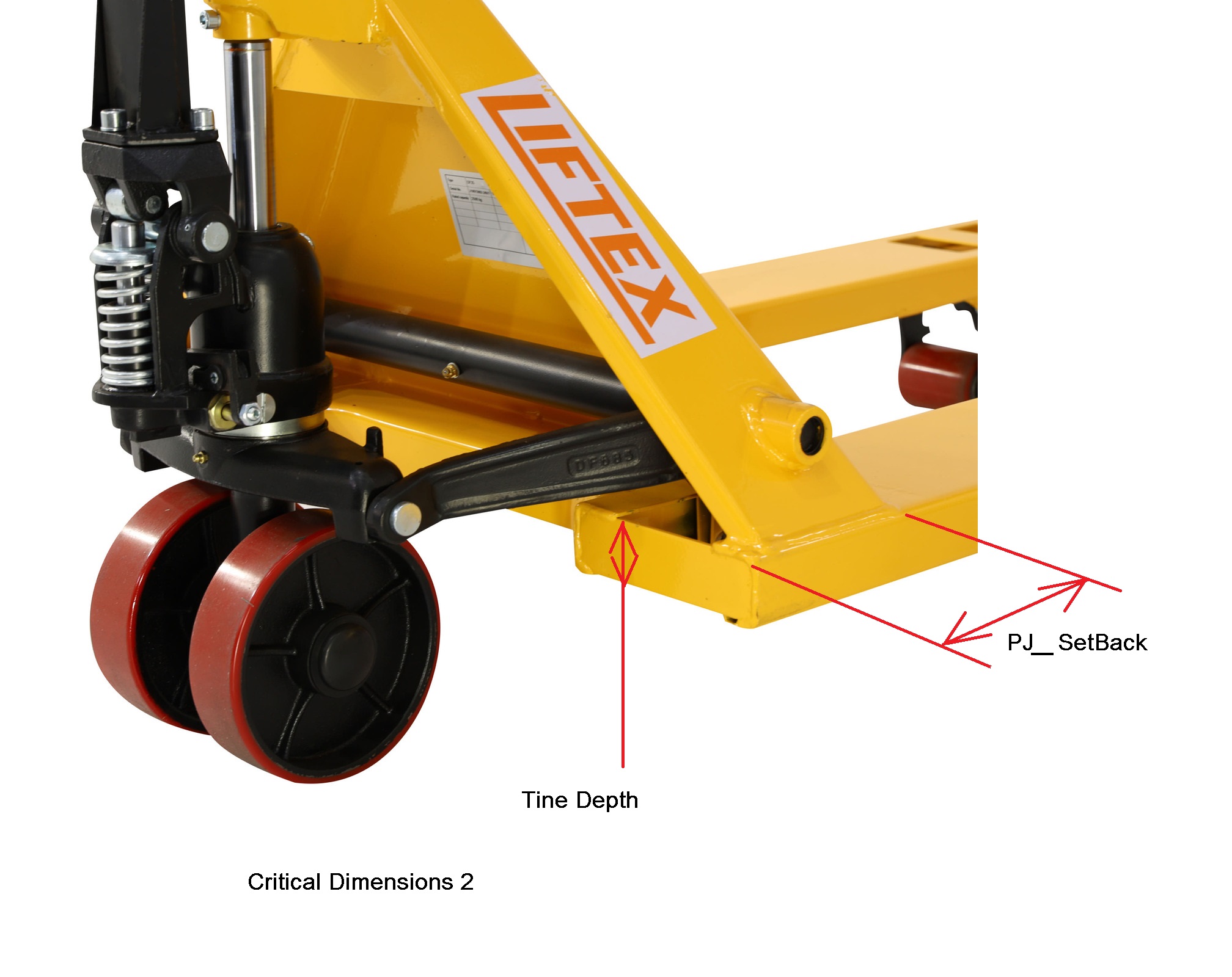
the distance between the pallet jack tines,
height of the tines when in the lowest positions (top of tine to ground)
the details of the winch mount (bolt sizes and centres)
and the dimensions of the pulley sheave (axle bolt size, hub width, and overall diameter).
Other dimensions are needed for stability these include;
the dimensions of the rear of the pallet jack,
and the distance of the setback on the crane straps compared to the mast base.
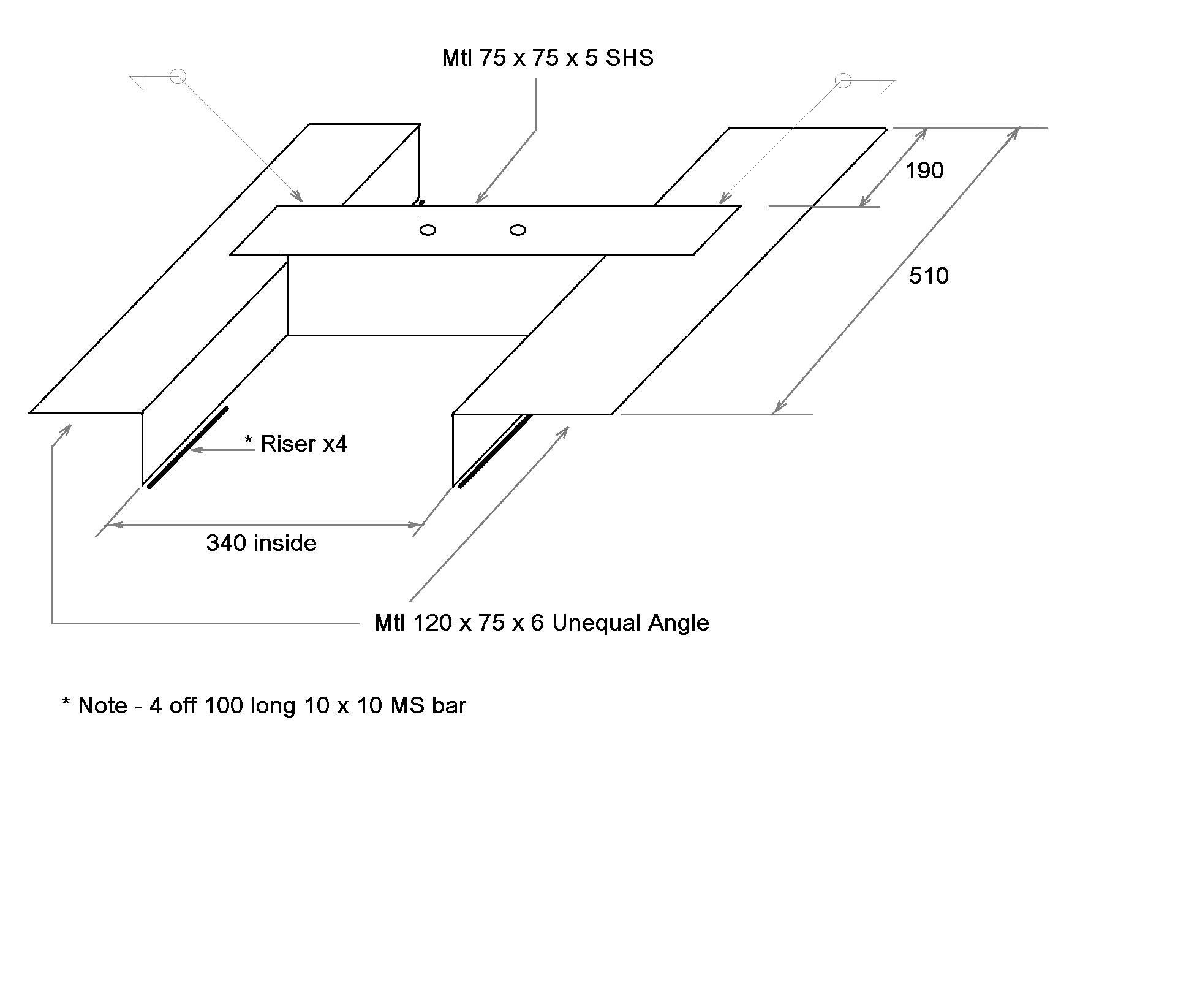
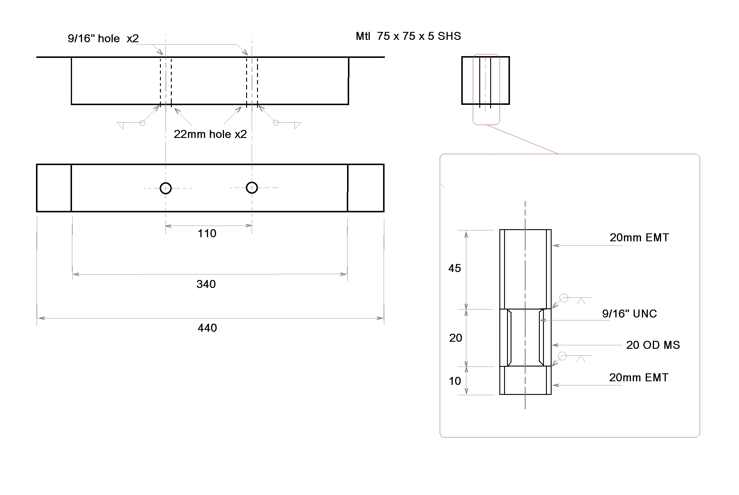
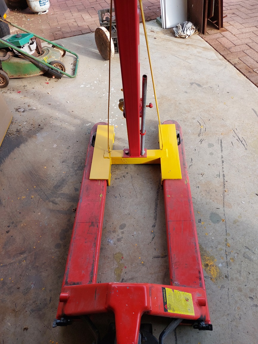
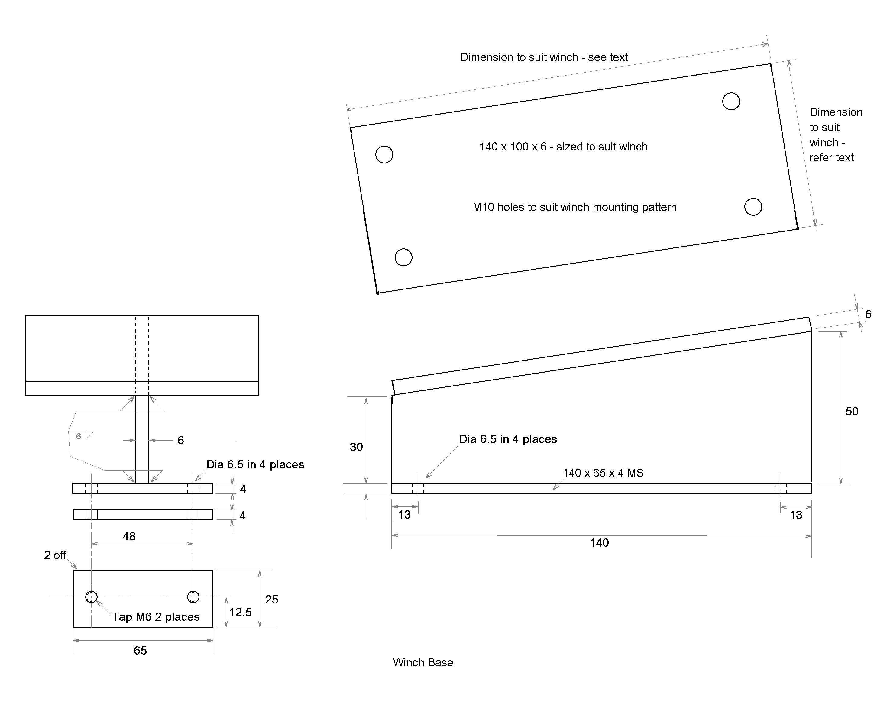
Step three make the base. The base of the device is a H shaped piece which sits on the shed floor whilst in storage, and the tines of the pallet jack can fit around/ under it to move it in and out of storage, and support the crane during operation. The distance between the tines of the pallet jack will dictate the length of the cross piece (minus allowances for material thickness, and operating clearances) and a suitable piece of SHS tubing was marked out to suit. The original crane base was made of 70x70x3 SHS, and I had some 75x75x5 SHS offcuts of a suitable length to make the cross piece. I marked and drilled the holes for the mast attachment bolts, and cut out the steel in preparation for welding. Refer sketch SK 1 for details.
The original mast base had 14mm bolts which passed through the SHS with exposed thread and a hex nut on the bottom surface. In my application, the thread and nut would cause issues with ground clearance, so I made up 2 sleeve nuts so the thread was contained within the SHS tube. Sketch SK 2 has detail on these sleeve nuts which were made using some common black steel bar, and some short lengths of round tubing (electrical conduit, or water pipe will suffice).
I drilled, bored and tapped the 9/16 UNC thread in the 20mm bar on the lathe, and faced the short lengths of pipe so I had good surfaces for welding them together. I then turned the welds down to nominal size to keep the sleeve uniform diameter. I could have used 14mm bolts, but did not have the appropriate tap in my set.
The holes drilled in the SHS were 9/16 clearance on the top wall of the SHS, and loose clearance holes for the finished sleeve nut diameter in the bottom wall. I bolted the mast base to the SHS using vice-grips to hold the sleeve nuts whilst the bolts were spun tight, and then fillet welded them in place on the bottom wall of the SHS. After disassembly, I ground the protruding sleeve down so it only protruded by ~4mm. The bolts used to secure the mast to the base were 3 long (75mm), so no thread from the bolt protrudes below the SHS bottom wall regardless of the mast base plate thickness.
The cross piece is positioned between 2 angle iron pieces such that the vertical legs of the angle have a clearance fit between the tines of the pallet jack, and the horizontal legs rest on the top surface of the tines. I used a clearance on the tines of 5mm. The cross piece is tacked in place and fit and squareness checked before completely welding in the piece.
The dimensions of the angle iron section used will need to be determined this is the process I used.
The overall length of the angle sections was to be the same or longer than the wheelbase of the original crane base, that would provide similar stability whilst in the folded (storage) configuration.
The width of the vertical leg was to be within 10% of the width of the walls in the original SHS since the resistance to bending in a beam is mostly influenced by the depth of the beam. The tines of the pallet jack contribute to that, but rather than calculate something that complex, I choose to remain close in size. The thickness of material in the angle section was to be close to twice the wall thickness of the original SHS base, since the new base had 2 less walls in the beam structure to reduce deflection. Luckily, I had some offcuts of 120x75x6 unequal angle which met all of my criteria, but I could have used 75x75x6 equal angle and still been comfortable with my material choice.
The offset from the rear of the pieces to the cross piece was to ensure that the back straps contacted the back of the pallet jack with an angle which prevented peeling forces on the mast base. The distance between the original crane mast and straps was used as a guide, and increased marginally to allow some ease in fitting. The straps have to be vertical, or angled so the top of the strap is towards the front of the pallet jack to achieve this. Essentially, if you copy the angle of the original straps, the forces on the mast base should be manageable by the mounting bolts.
Once the base was welded up, I then added some small feet on the lowest edges of the angle to ensure the tines of the pallet jack (when in the lowered position) could slide underneath the base with a clearance of approx. 5mm. This clearance allowed for any deviations in the floor of the shed, or debris adhered to a wheel of the jack. This clearance, plus the inherent stability of the base when folded means I can use the tips of the tines to pick up the finished unit from its storage location in the shed, move it out into the centre of the shed floor, put it on the ground and then slide the entire length of tines in to position it on the jack properly before attempting to use the machine.
NOTE - The feet were 100mm lengths of 10x10 square bar, but had they could have easily been adjustable screw feet, or offcuts of some other steel section. Looking back, if I was to make another version of this machine, I would use short lengths of angle section with the feet on the inside, and that would allow the machine base to be easily positioned with a standard moving trolley, as well as the pallet jack tines.
Step four the strap connectors. At the conclusion of Step three, the base is fabricated, and if the crane mast (with jib and boom) was bolted in place, the unit is quite stable in the folded storage configuration, and testing showed that my unit was stable with the jib extended to horizontal, with the boom fully extended. HOWEVER, it only took a heavy touch (say 2 kg down force) on the boom tip and the machine would attempt to topple off the pallet jack.
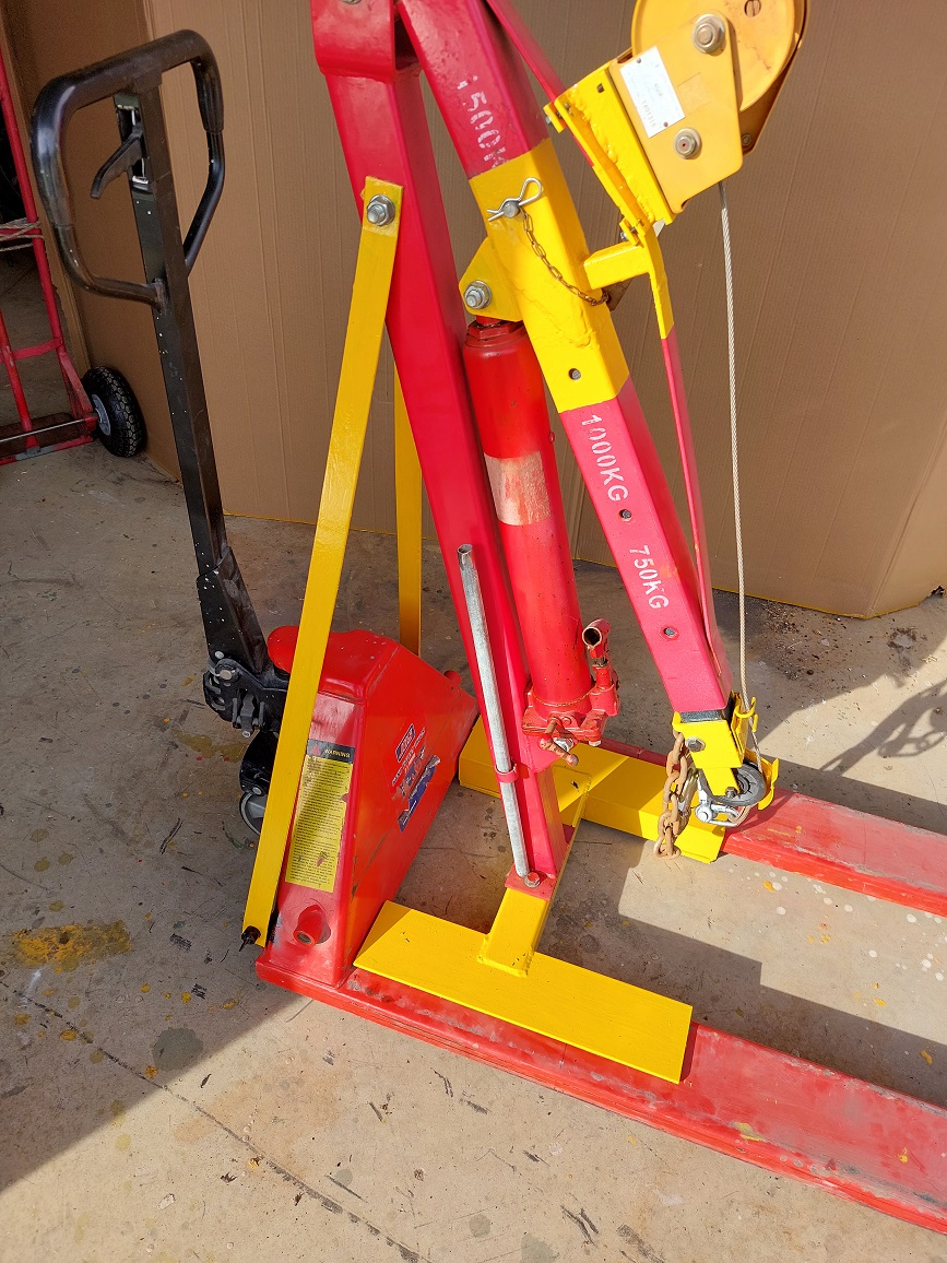
The original crane design has two 40mmx 4mm straps which are bolted high on the mast, and connect to the base some distance behind the mast base plate. These straps prevent the forces on the mast from peeling the base plate bolts, and add incredible stability to the mast when it is loaded.
The straps from the original crane are retained at the mast connection by a single bolt at the top which connects a strap on each side of the mast, and one bolt per strap at the bottom. The bottom of the straps is splayed out to add rigidity against sideways movement. In order to retain that effect, the bottom of the straps is brought to the rear of the pallet jack, one on each side. NOTE if you are planning to reuse the straps from an original crane, take note of the bolt hole size at the bottom connection my crane was 16mm bolts, with clearance holes to suit.
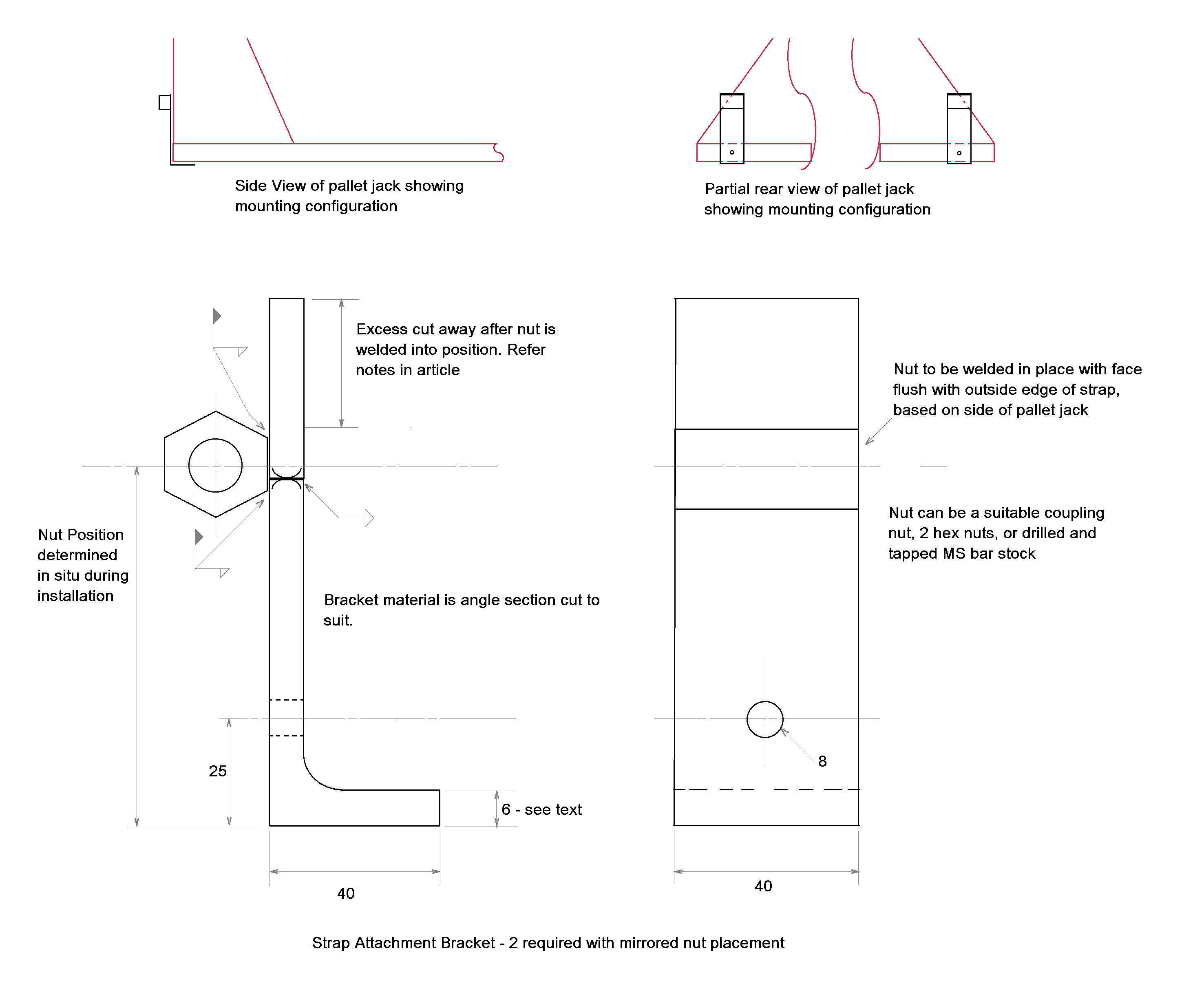
Two L- shaped brackets are made up with a short (40mm) leg designed to sit underneath the rear of the pallet jack (the back of the welded tines), and sit flush with the rear surface of the jack. I made my brackets from 40 wide cuts of the angle section used to make the base, and I cut one leg at 40mm long, and then welded the cut of pieces to the other leg to make it longer for the fitting stage. A single hole (8mm is what I chose) is marked and drilled so it intersects the centre of the tine depth. My tines were 35mm deep, and the thickness of the leg was 6 mm, this means the 8mm hole would be positioned at 6mm, plus 18mm (6 + 18 = 24 which I rounded to 25) up from the corner of the bracket. Refer to sketch SK 3 for an overview of these brackets.
A pair of bracket nuts will need to be sourced or made. These are to receive the bolts which retain the strap, so in my case should be M16. Since I did not have any long (coupling) nuts in M16, and no tap in M16, I chose to use a pair of standard M16 hex nuts to make up each bracket nut. It is better to use a coupling nut or fabricated deep nut (drilled and tapped bar stock), since 2 hex nuts welded together are prone to binding due to welding distortion which can only be eased by passing a tap through the finished nut.
With the crane mast bolted to the baseplate, and the pallet jack lifted high, a pair of clamps can be used to stop the crane toppling as you position one strap to the back of the pallet jack, and mark an approximate intersection with the angled rear of the jack. (I used a strip of masking tape on the side to mark the hole position)
Position the bracket (L piece) so it intersects the mark so a nut flush on the bracket would be completely proud of the rear of the jack when viewed parallel with the tines. Drill the mating hole through the rear of the jack tine, or use a clamp to secure the bracket in place.
Place a bolt through the bottom hole of the strap, and affix the nut so it is tight. Position the nut against the back of the bracket ensuring that the face of the nut is flush with the bracket, and the strap is not binding against the sloped side of the jack, and tack weld the nut into place on the bracket.
Repeat for the other side strap the alignment of the nut to the outside edge of the bracket will make each bracket a mirror image of the other.
Remove the bolts and remove the brackets from the pallet jack. The nuts can now be fully welded to the brackets, and any excess metal removed from above the nuts.
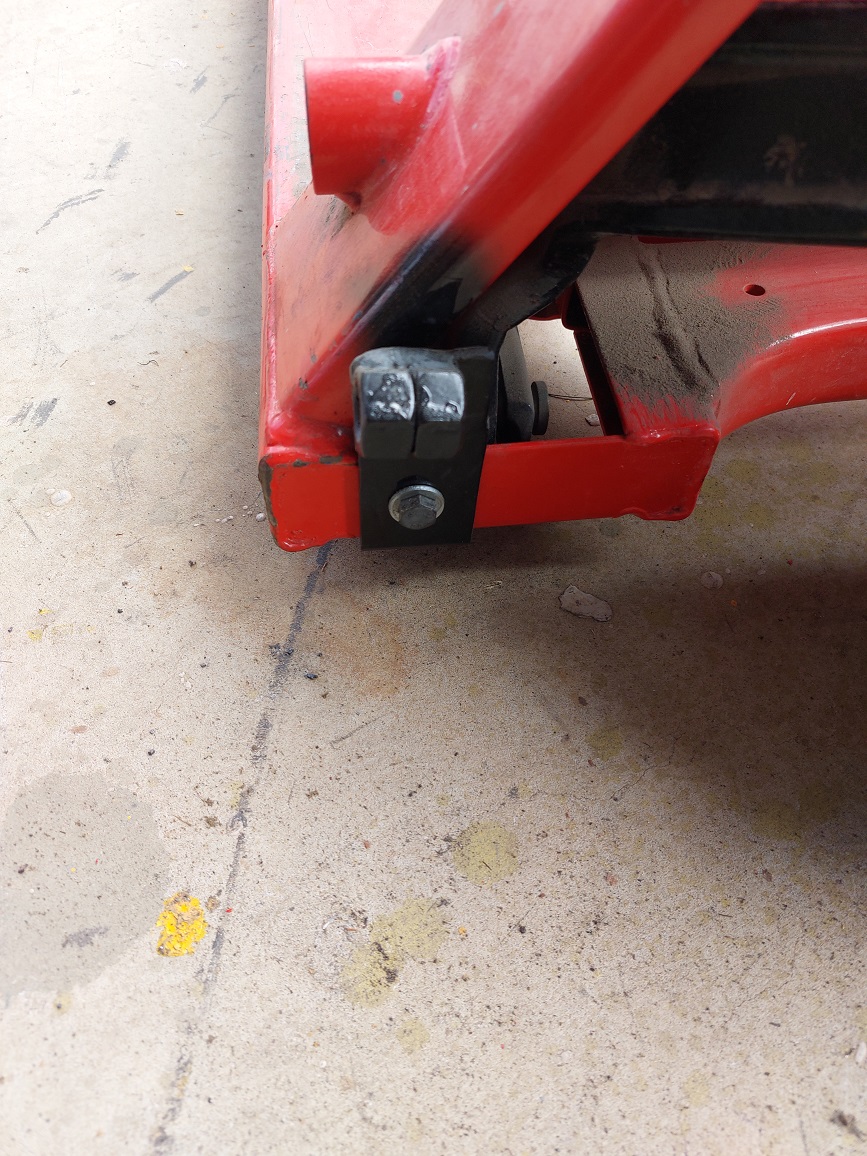
The two holes (M8 in my case) drilled into the back of the jack tines are the only modifications made to the pallet jack, and the brackets can be left in place with no impact on operation or footprint of the pallet jack. I recommend the use of lock nuts or nylock nuts to ensure the bracket retaining bolts do not come loose in normal operation of the jack. Photo 7 shows the bracket in place on the rear of the pallet jack.
My installation uses M16 bolts for the lower strap connection, in order to make this a tool-less installation, I welded thumb tabs on a pair of M16x50 SHCS. The tabs are short enough that they do not stick out the sides of the jack footprint, and approx. 45mm wide, enough for me to tighten into place by hand.
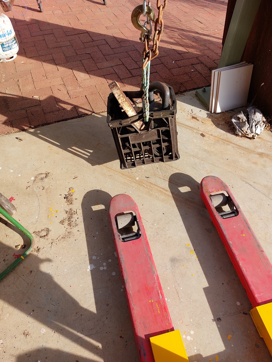
As noted earlier, an approximate 2kg load on the boom tip was enough to topple the unit without the straps connected, but with the straps connected to the brackets, the crane should be able to perform at original design capacity (typically 2T). At the time of writing, the heaviest load I have lifted has been just over 380 kg, and the unit was quite stable through all motion tests. The photos will show a test load of 120Kg (milk crate filled with lathe chucks, faceplates, steel offcuts, and kettlebell weights), but I've since used this to pickup my 12" Douglas shaper which weighs approx 400kg.
NOTE Step 5 and 6 are about the addition of a winch to increase versatility of the unit, these additional steps could be considered optional if the range of motion required is already met with the hydraulic jib and pallet jack movements. The other advantage of the winch installation is that I can use the winch independently of the hydraulic lifting, allowing me to use it for trimming a lifted load for alignment should the situation require it.
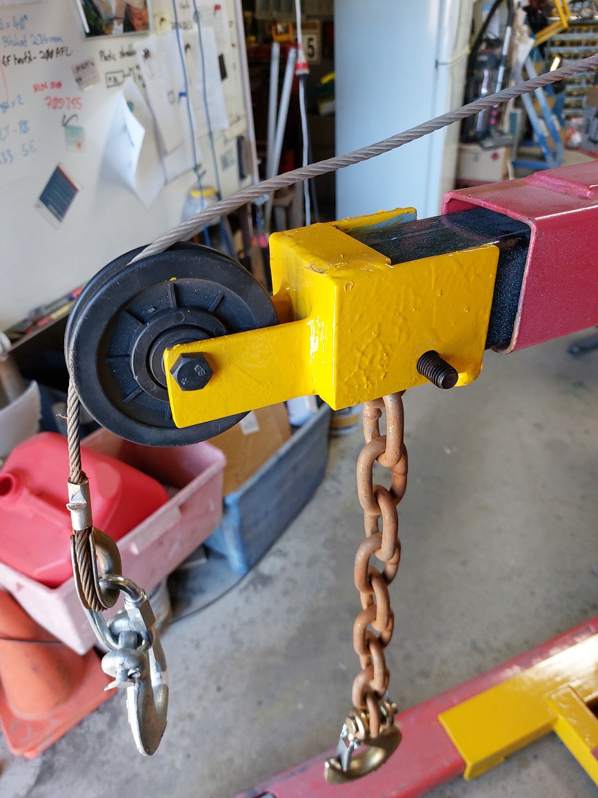
Step five the nosepiece. This is fabricated piece which is a slip fit over the end of the extending boom section of the jib. In most engine cranes, this is a SHS piece with a single bolt and slot arrangement to connect the hook chain to the crane. Since I utilize this bolt hole to retain the nose piece, some measurements need to be taken from the donor crane.
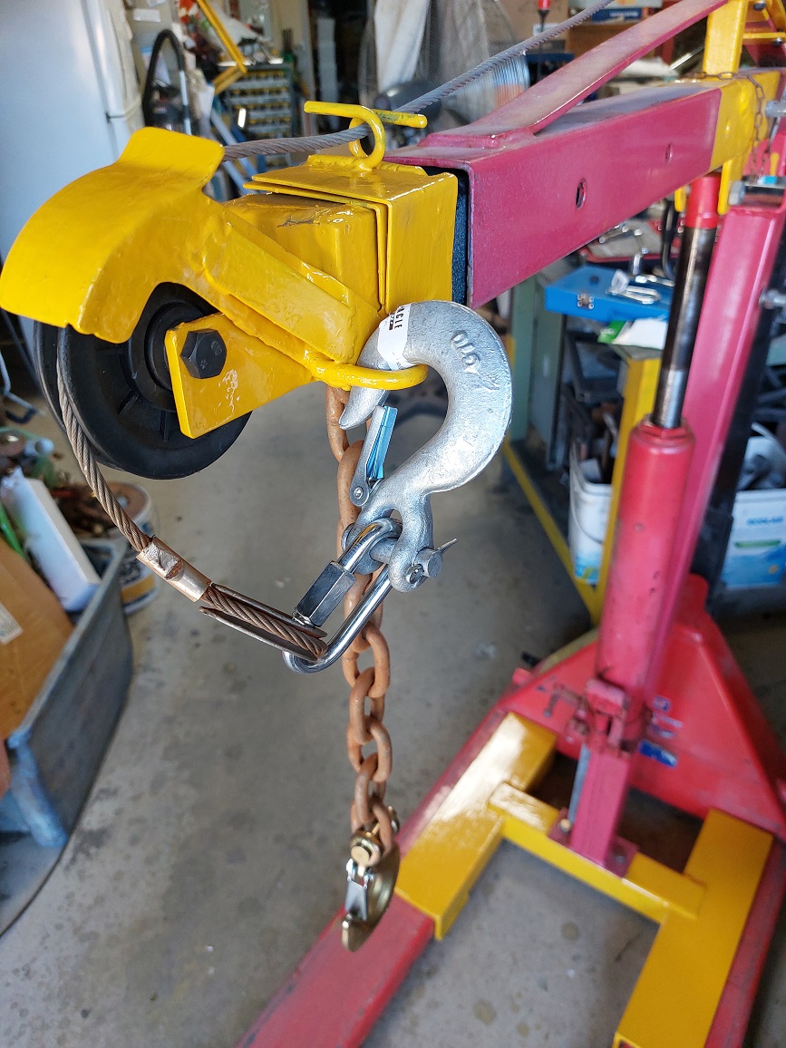
The fabrication is simply built up around the SHS, with a suitable clearance (I added a couple of millimeters). The pulley sheave from an exercise machine was used to redirect the winch cable, and a pair of stand-off pieces made to support the axle bolt. I positioned these stand-off pieces such that the pulley rim sat approximately 10mm above the top of the nose piece so the cable would not rub on anything along the path of the jib. Photo 8 is a good overview of this piece.
The original hook chain bolt may need to be replaced with a longer one to compensate for the thickness of the cheeks of the nosepiece.
I have supplied example drawings of the nosepiece I made with dimensions which suited my donor crane, you will need to determine any adjustments to suit your crane, and pulley dimensions. Refer sketch SK 4.
You will see in photo 9, I also fabricated a 2-piece guard which provides a cable guide between the winch and pulley sheave, and then forms a cover over the pulley sheave to reduce the stiff winch cable from rising out of the pulley when unloaded. There is also a loop mounted on the side which allows the hooks to be clipped to it so they arent flapping around when the machine is in storage.
This guard is retained by the same hook chain bolt, and both pieces are mounted from the same side to make it easy to fit. I have not included any sketches of these guards since they were simply fabricated on the fly from light weight gal sheet.
Step six - the winch base. I selected a 500 kg winch and made up a base plate to suit it, ensuring I did not utilize any mounting holes in the centre line of the base plate. My base plate was 140 x 100 x 6 MS, with 4 x 10mm holes for attaching the winch. Check your winch to ensure it is pointing the right way since most winches have a direction marked for the cable to operate in. This is particularly important with any type of brake winch.
I then determined the angle to mount the winch so the cable would not rub on the job/ boom at any extension setting. I did this by holding the leading edge of the winch against the strap, and lifted the back edge until the cable was clear. I measured the lift and used that as a rise vs run to determine a starting angle. The determined angle was then offset by an additional distance to allow room for bolts, tools, and welding operations to occur between the plates which will be above and below the centre web piece. I then made a wedge-shaped piece to go between the base plate and the tension strap on the top of the jib.
The strap on my crane jib is 40mm wide, so I made a clamping plate from 140 x 65 x 4 MS, with 4 off 6mm clearance holes spaced on 48mm centres, spaced 13mm from each end of the plate. Two matching straps were made from 25 x 4 MS strip in 65mm lengths with M6 tapped holes on the same 48mm centre spacing. These dimensions are outlined in sketch SK 5.
The wedge shaped web was welded to the centreline of the plates with a fillet weld on each side of the web.
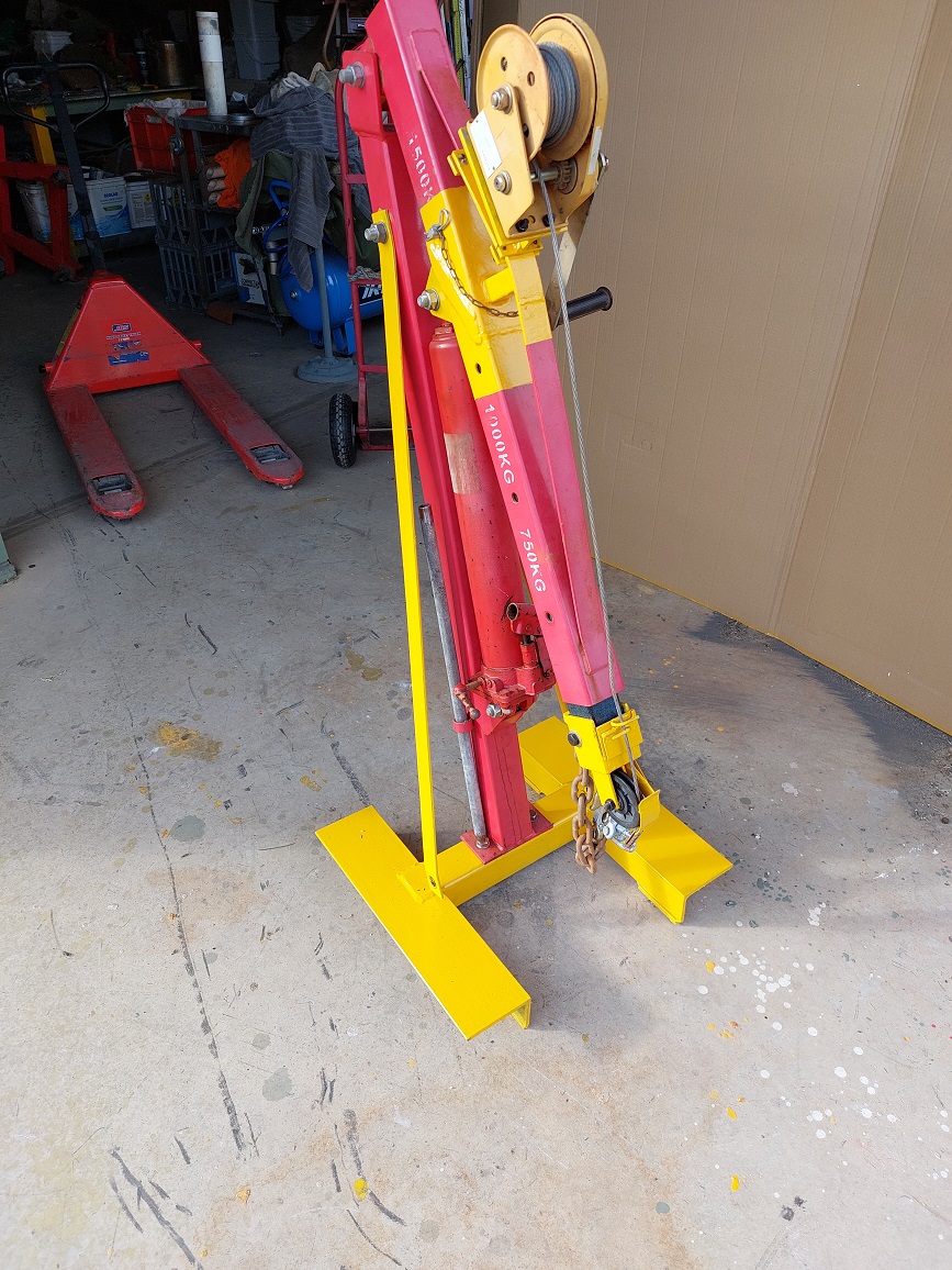
After cleanup and painting, the winch base was mounted to the top strap of the jib using 4 short M6 bolts, and then the winch was bolted in place using the appropriate size bolts (M10 in my case). The cable was paid out through to the pulley sheave, and a hook attached to the thimble eye. Photo 10 shows the conclusion of mounting the winch.
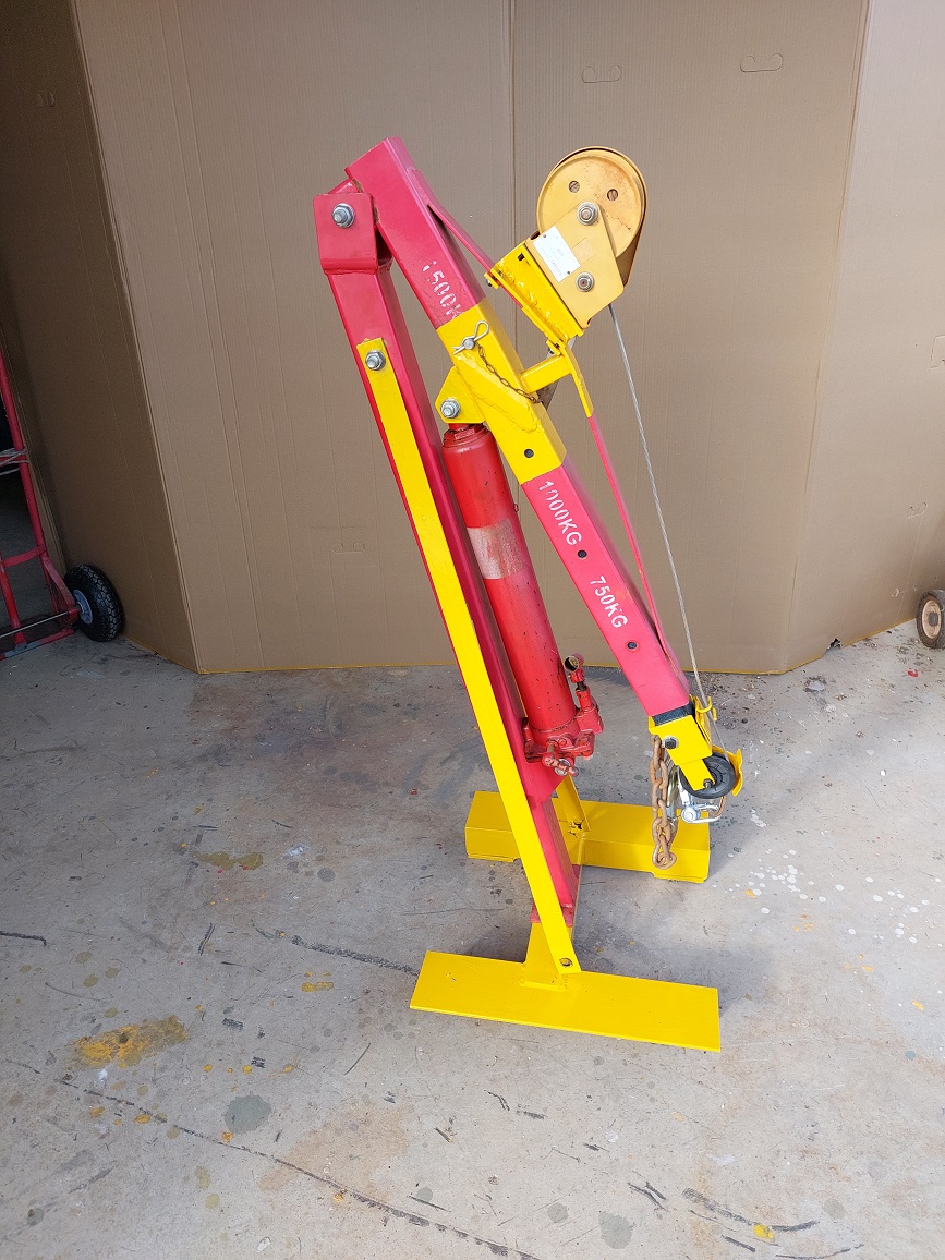
That concludes the fabrication of all the components, all parts were primed and painted and assembled for use.
Notes on use of the device.
Someone asked what its called I call it a Bitsa-crane since its bits of an engine crane, bits of a pallet jack, and bits of a winch, plus whatever else I add on for the lift.
I found with my winch, I gained 3mm for each click of the winch, and could get very fine control using a combination of the hydraulics of the jib ram, and the pallet jack.
You will quickly develop the habit of paying out the winch cable before attempting to extend the boom, otherwise the cable will restrict movement.
I used a maillon (aka quick link) to attach the hook to the thimble of the winch cable, this allows me a high degree of flexibility to change the hook for some other lifting device to suit the job at hand. Equally a maillon or shackle could be used to change the hook on the hook chain. Remember that ALL components of a rigging set-up should be rated for the load (including a safety margin), the failure point will be the weakest link, and that link could be parts of the bitsa-crane, or it could be a weld on the load, a rope, a sling, or bolt, or any other component in the load path.
The original crane manual (or various online copies) outlines guidelines and rules regarding the use of short as possible boom extension, and keeping the load within the footprint of the crane to avoid toppling. These guidelines apply to all lifting arrangements, and this device is bound by those as well.
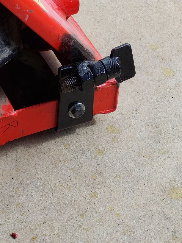
Always ensure the jib boom is locked in place with the cross pin as originally supplied. These typically come with a wire R-clip to lock the pin in place, I added a short length of chain between the pin and R-clip so I couldnt lose the clip.
a few extra photos of the unit


 Reply With Quote

Bookmarks