
Originally Posted by
Toolmaker51

"Note you know how to make this a 2 way conversation" That is a big issue in education; only good teachers encourage that, and our Frank S is one of the best.
I'm relearning the lingo, but can describe well enough
Correct; 4 identical momentary switches, all SPST (On) Off. Amid disappointment that design isn't offered SPST Off-On to place in *4, justifying the latching relay instead. Not unlike an E-Stop, just not so obvious an invitation for pinheads to mess around with.
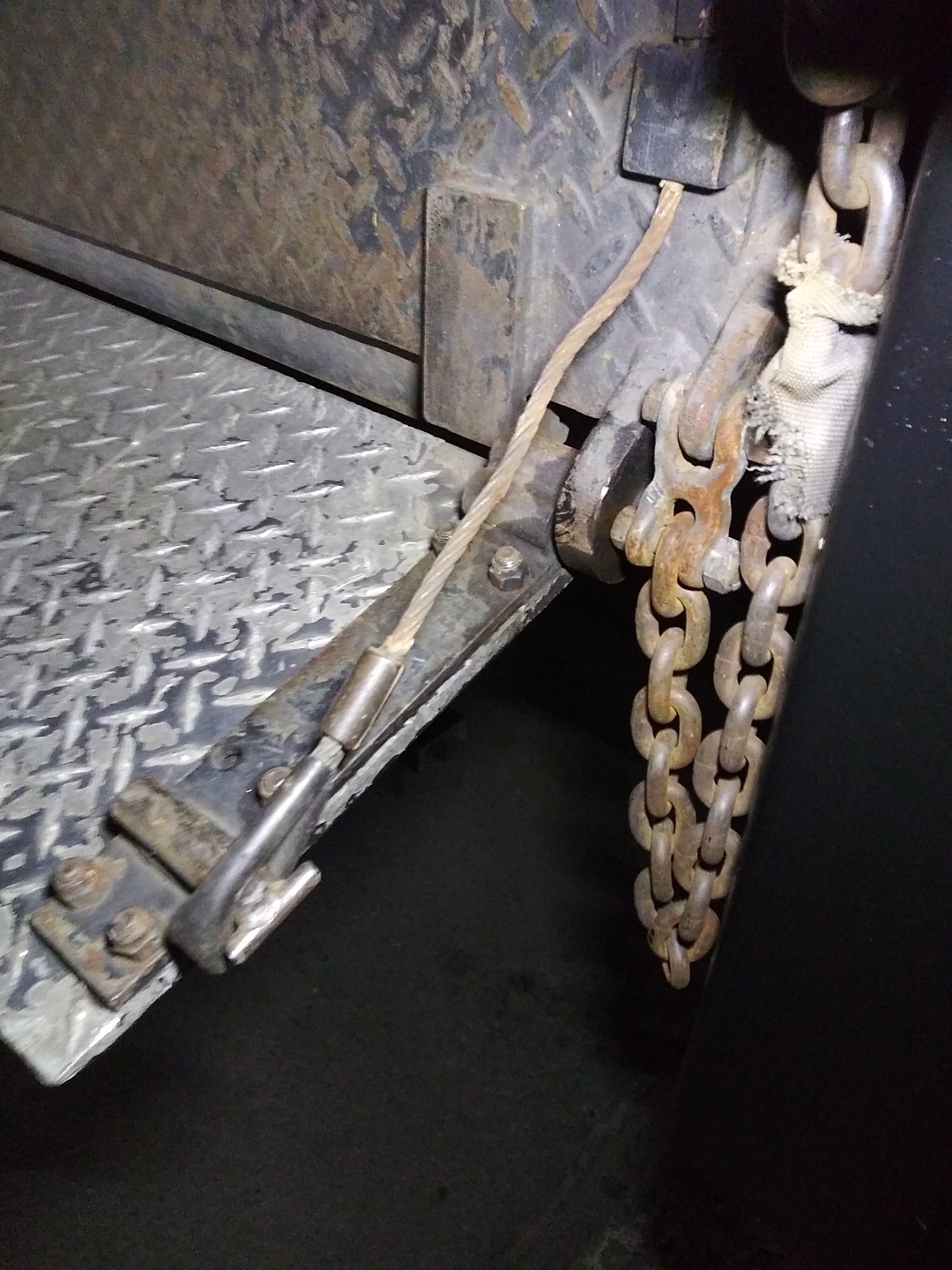
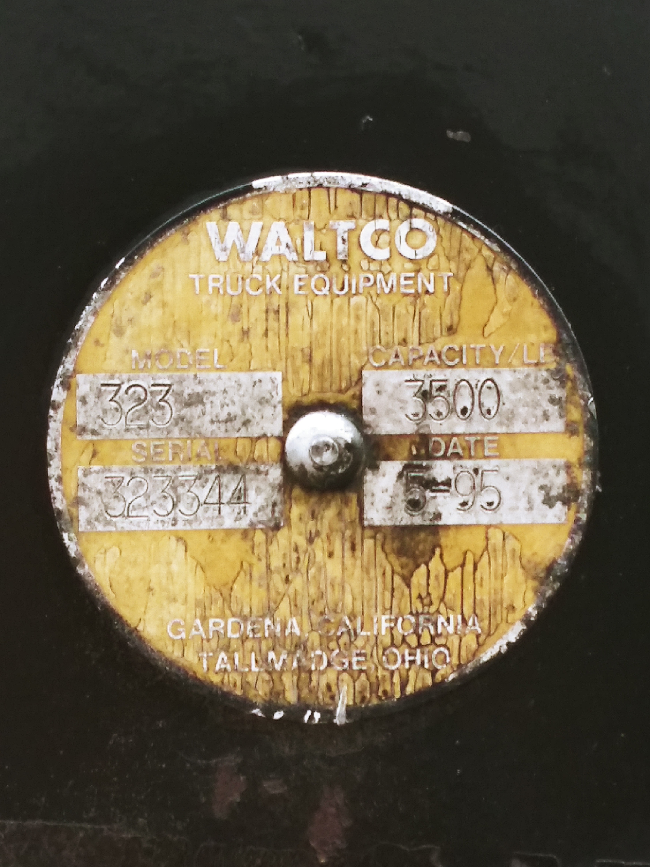
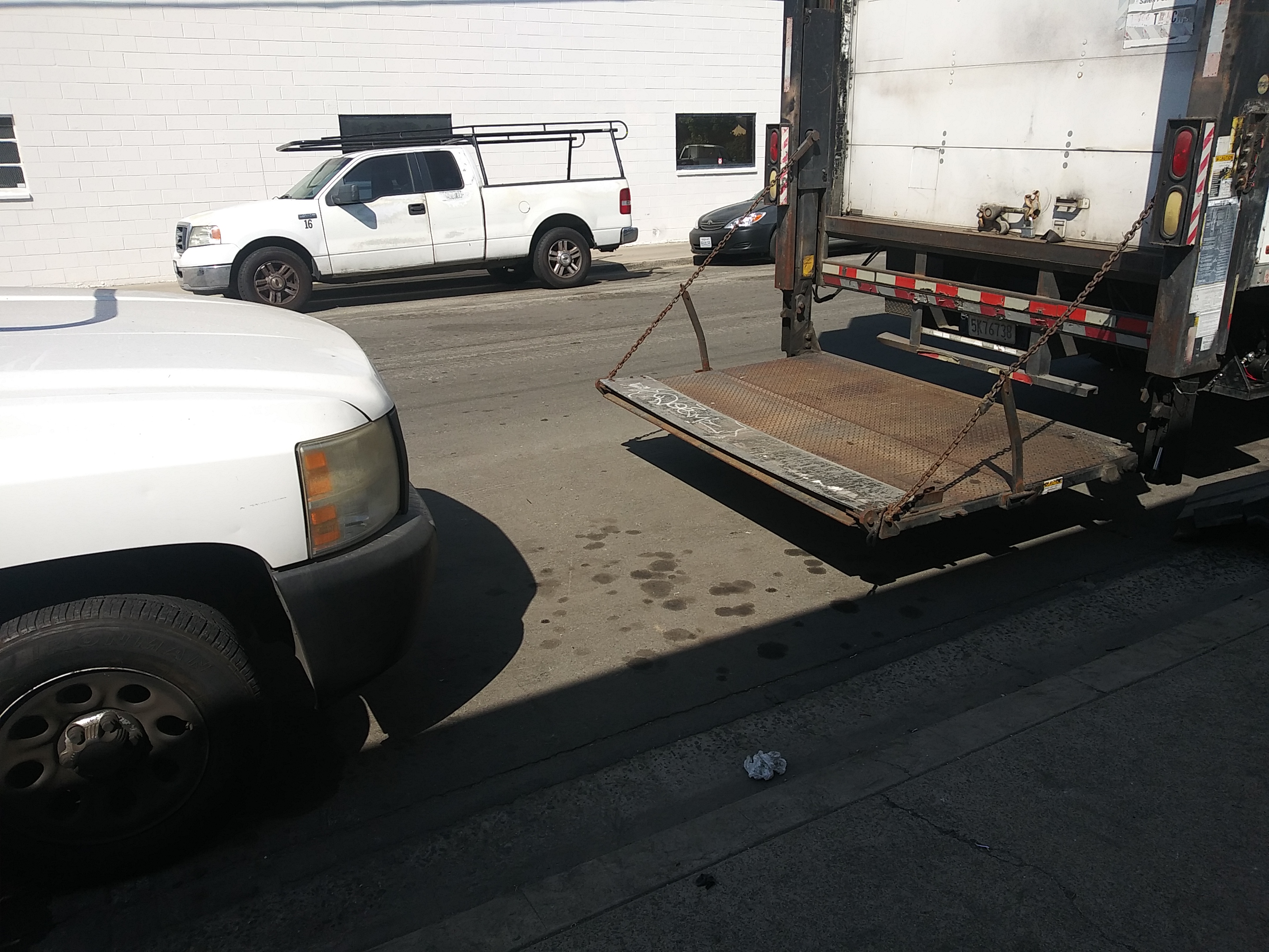
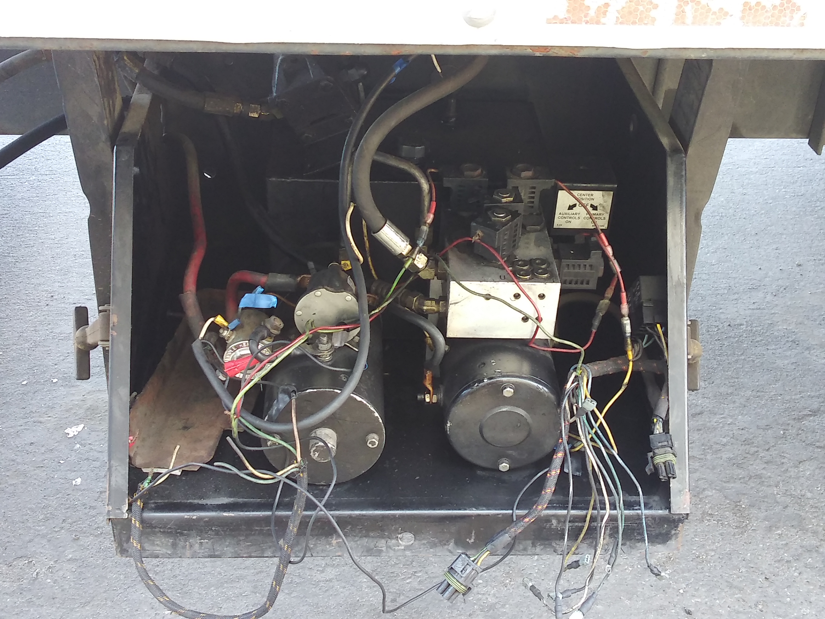
Lift-gate is a Waltco made in 1995, with 1 main pump and a standby. I'd bet anything main pump is same motor as a Delco starter.
The replacement loom has four leads for operation switches, for that year of manufacture, today's are different. Had to get help from a local liftgate mechanic, my process of elimination wasn't working, didn't realize second motor was a standby. Condition of the old loom wasn't much help either. Anyway, I had the loom in right, he joined the terminals of 4* and presto. Greased some fittings, took some measurements, he had the rest going in short order.
The latest switches are in exactly as he did, WITH intention of making 4* operative as a safety lock-out, forcing deliberate usage, just 100% upgrade in weather resistance. I tested briefly, it works as expected, but full test wants to warm up engine and fast idle to maintain battery power, the gate isn't self powered electrically.
Haven't done anything that would alter from running right; old switches were sticking in ON position and gate would descend (gravity+ open solenoid) by itself, unless finger was removed from switch smartly, just letting go wouldn't. UP did same, tending to push limit switch, another undesirable action. Don't know what that platform weighs, it's considerable. Not something I want running amok.
What I've learned unexpectedly, isn't just saving receipts, but labels or containers parts come in. Makes me a little smarter describing specifics, and I'm doing a note page of steps taken.
Even baby steps.

 LinkBack URL
 About LinkBacks


 Reply With Quote
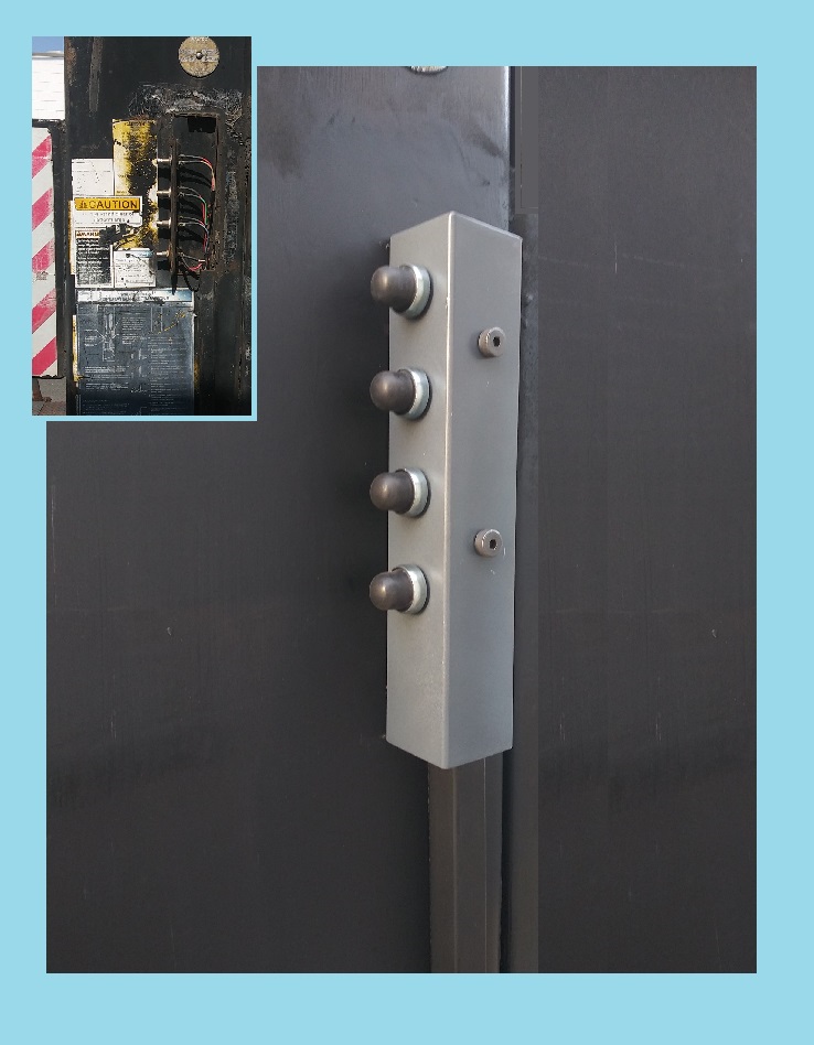


Bookmarks