
 LinkBack URL
 About LinkBacks


I thought i had better add some more pictures to wet the appetite, i'm still formulating the the build instructions and getting all the drawings together. I have realised that i will have to put the printed circuit board layouts onto pdf as the software i use (Proteus)
does not seem to transfer files well to other vendors software, I will however be producing the Gerber files which should be transferable. The mechanical files will be in DWG format.
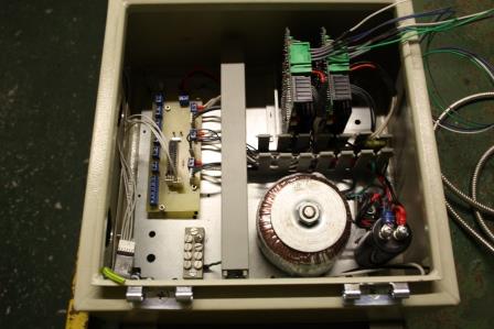
My Electronics have been built into a IP67 Enclosure
The power supply is producing a regulated 48vdc for the stepper drivers and motors, as these are industrial beasts and paired, i didn't see much point in changing anything. Having read numerous posts on stepper drives it looks like makers like us need to look more closely at the voltage and amperage of our motors and using the right sized stepper drives to suit our needs. Stepper motors are quite forgiving and will work on voltages higher and lower than those specified Its then up to the stepper drivers to handle the correct amount of current. The actual load/torque required for driving an X,Y,Z table isn't actually that high. The Nema 17 12v motors are just as capable of driving a table as those i have used. hell there is some grotesque 3D printer builds out there which manage to build some reasonable stuff. Always remember, trial and error is a well practice method of engineering. The bouncing bomb may have been mathematically and scientifically designed but the targeting came about by accident using a home made sextant and trilling the drop height until it was perfect, victory was built on such precise guess work. My ideology is don't waste money, try not to spend money, recycle every thing possible and leave the maths and science to the boffins-whilst they are talking about it i'm building it. I saved my last employer a fortune in his Petroleum R&D company.
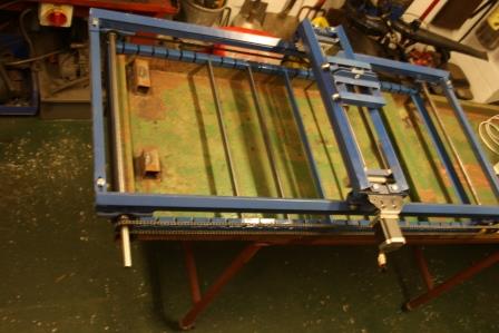
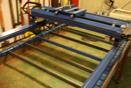
The Plasma table start with the bedways/axis, you need to decide how big you want to make this thing. making a cutting area larger than an 8 ft x 4 ft sheet of steel is probably pointless for DIYers, then you have got cranes/hoists etc to get the plate onto the machine etc. I aimed for 3ft x 3ft and failed miserably OK one way but the Y axis i limited myself by recycling the lead screw.
I will use the table i have built for now until i grow out of it.
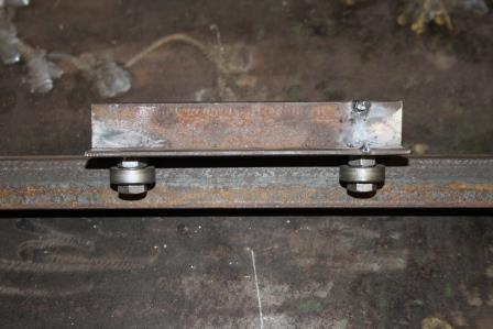
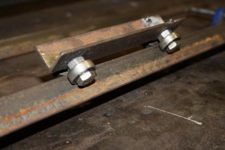
slides for axis.
I found a few pictures of various designs of slides on this very site. some required a plasma cutter to cut out various shapes - hello, i haven't built the thing yet. So following my non scientific farmer son approach i went for a simple design.

I ran the slides on a 1" steel angle, up to 4ft this should be reasonable strong and take the weight of the Y axis carriage. if your intention was to build a larger machine then i would consider using 1 1/2" or 2" angle.
due to the expense of acme threaded worm screws and all the hardware required to hook them up, i opted for a chain drive which works perfectly. I had the added advantage of having a right angled 10:1 ratio gearbox, to be fair i used it to reduce the profile of the machine rather than needing the extra torque for the X carriage. The right angled gear box gave me the advantage of attaching the motor along the side of the frame instead of it sticking out at 90 degrees.
Well i hope this is enough of a taster to get you hooked
more to follow
Jason.

 Reply With Quote

Bookmarks