
 LinkBack URL
 About LinkBacks


A while back I had a couple of cylinders for my Aermacchi classic racer which needed reboring. There is nobody in my area who does such work that I know of, so I decided that I would do it myself, but I do not have a cylinder boring machine. The quill movement on my mill is a little too short, so I had to use the lathe. The obvious way would be to spin the barrel and use a fixed tool in the usual lathe manner but there are several good reasons to do the opposite, that is, spin the tool not the cylinder. The first stage was to make a really solid boring bar with easy diameter adjustment. My lathe has a no.5 Morse taper in the spindle which is plenty beefy. I had a length of 51mm 4140 bar of just the right length, so I turned a MT5 taper on one end and threaded the other end to accept a commercial boring head. To ensure rigidity right to the cutting edge I make a solid holder for a carbide insert, which is held into the boring head by two 1/2" pins. The next stage was to make a mounting to support the cylinder rigidly and accurately. This was welded up from pieces of steel from my scrap box and initially machined on the mill with a final truing cut taken with a fly cutter when mounted to the lathe's cross slide to ensure perfect alignment. The hole in the plate to locate the cylinder was also finished in-situ. What is commonly known as a "torque plate" was made to hold the cylinder in place. Now it is ready to go.
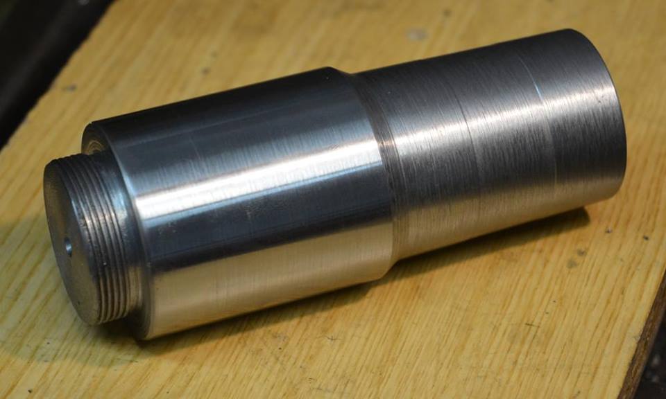
The bar made to accept the adjustable boring head. I like rigidity when machining. Note MT5 taper on one end and threaded for the boring head on the other.
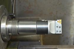
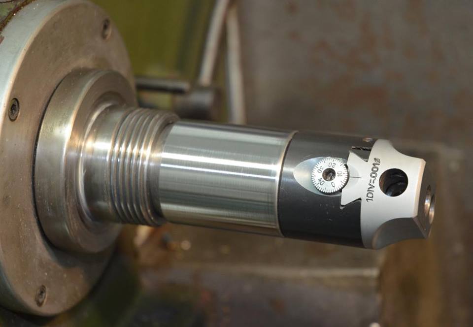
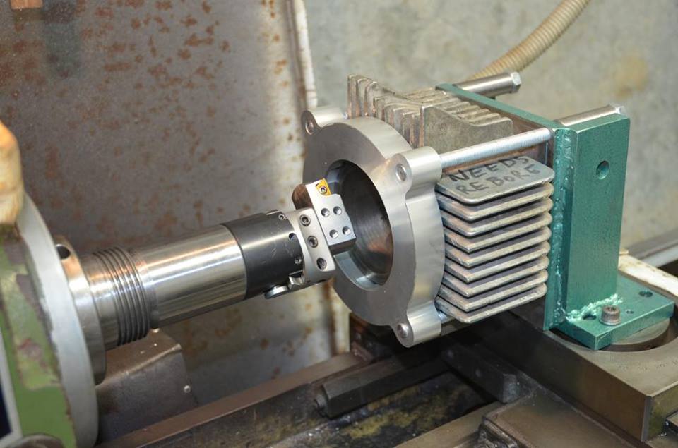
Two sides of the boring bar fitted in the lathe and with boring head attached. Note the rigid insert holder in the first pic.
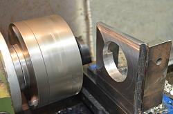
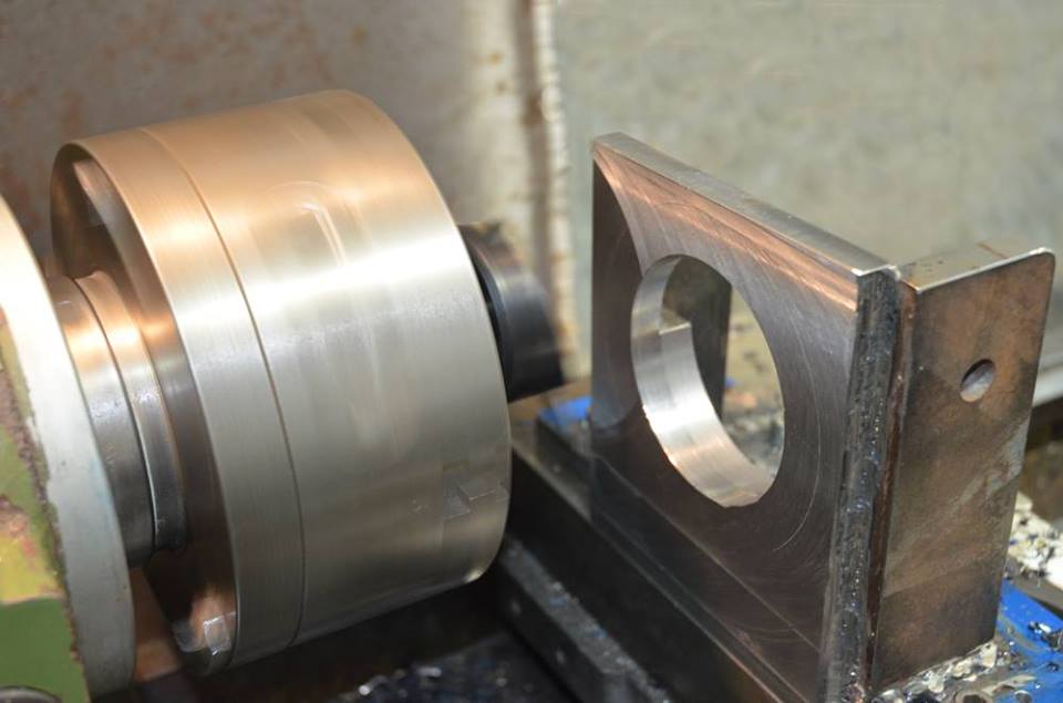
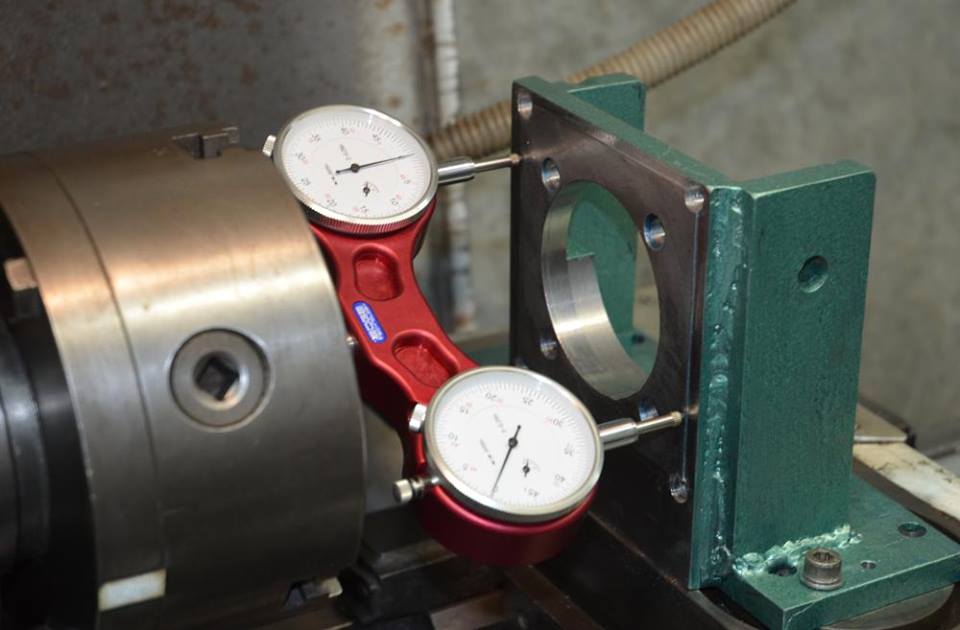
Firstly using a fly cutter to face off the mounting plate square to the spindle axis. Secondly tramming the mounting fixture after refitting to the lathe.
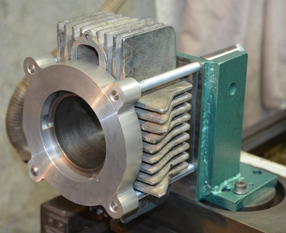
Cylinder mounted and clamped with a torque plate and then it is ready to do the important bit.


 Reply With Quote

Bookmarks