
 LinkBack URL
 About LinkBacks


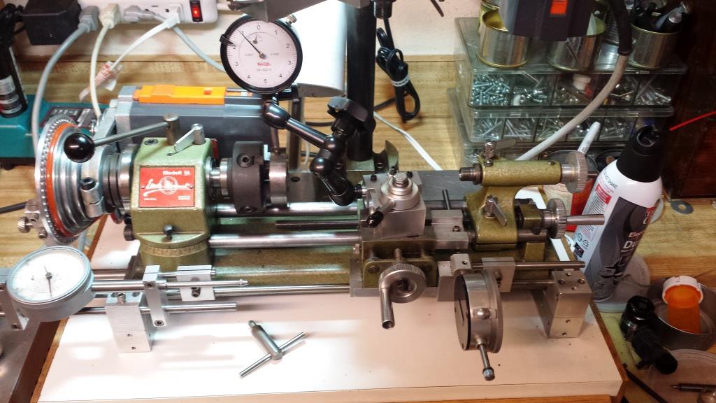
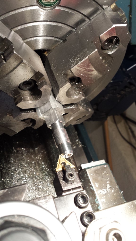
Space is limited for using a dial indicator (DI) on my small 3” swing Unimat lathe for 4-jaw chuck setups. Most of the lathe is made from non-magnetic parts and also has very little room to attach a magnetic base where there are ferrous metal parts. Using a boring tool holder in the QCTP (quick change tool post) works but this requires changing the cutting tool holders and possibly resetting the previous tool position (see photo below).
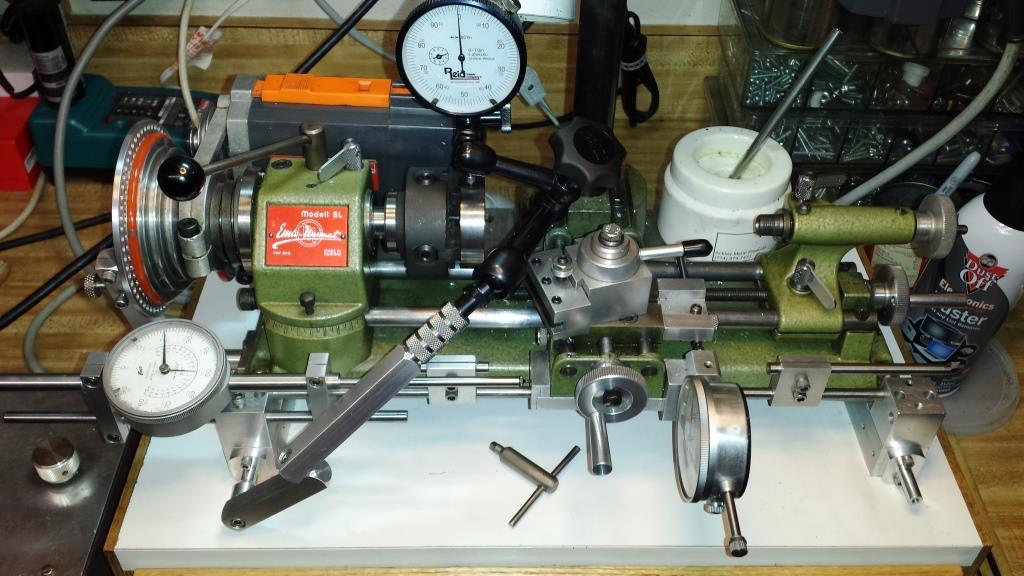
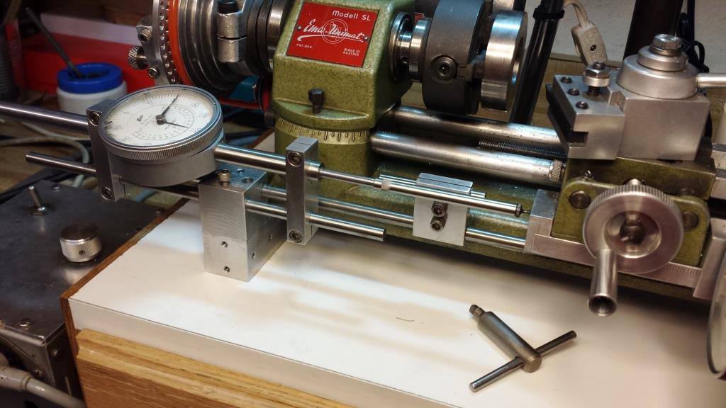
My solution uses a separate adjustable arm extension and attachment bracket for a small Noga adjustable arm DI holder with an 8 mm clamping rod. The adjustable arm extension is made from ½” square 6061-T6 aluminum and 12L14 steel rod materials.
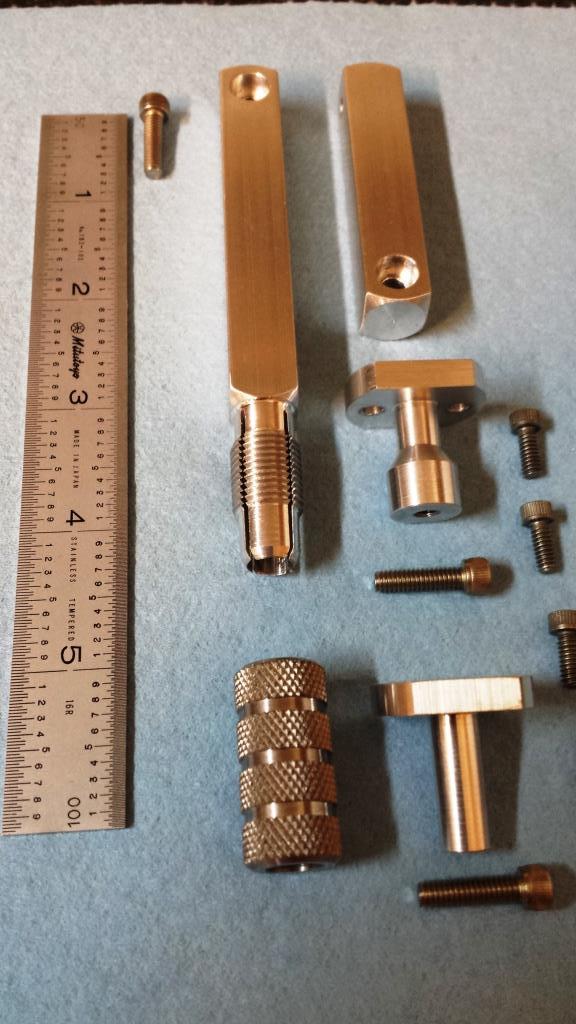
The Dial Indicator Adjustable Arm Extension parts were created using the milling head to the 3” swing Unimat lathe, a 7” swing mini lathe dedicated to collet work and a 12” swing geared-head lathe. These are the parts for the Dial Indicator Adjustable Arm Extension.
I designed the riser blocks for supporting the Unimat SL lathe on a small cabinet. The riser blocks include several pairs of 6-32 threaded holes along the block sides and ends for “future” attachments to the lathe. I am already using one pair of threaded holes behind the headstock to hold the detent arm support to the dividing plate (see http://www.homemadetools.net/indexin...nimat-sl-lathe). Using a similar method, I added support brackets to the headstock and tailstock riser blocks and still have plenty of pairs of threaded holes for other uses.
The aluminum rod extension made in two parts is ½” square and 4.5” long with a 8 mm rod clamping end and a shorter piece 2.5" long for allowing side-to-side adjustments. The clamping end has a 8 mm by 2” deep hole that is externally threaded ½ X 20 and with four 1.1” long jaws formed from the slots. There is a knurled 12L14 steel collar internally threaded and with a internal tapered end to compress the four jaws. The 8 mm rod of the Noga adjustable arm DI holder fits into end with the four compression jaws and is clamped in place with a internally threaded collar. Note: before finally assembly, an 8 mm dia. drill was used to "cleaned up" the 8 mm by 2" deep hole after partially threading on the knurled steel collar (not yet to full compression) to ensure an exact fit for the Noga 8 mm support rod.
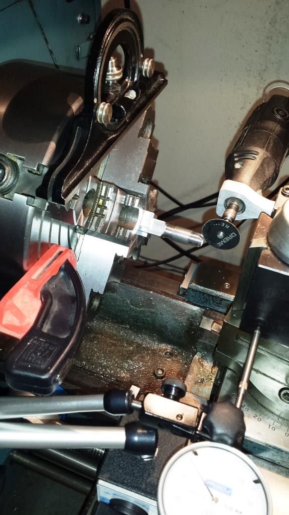
The four slots forming the jaws were cut with a 0.045" thick abrasive cut-off wheel and Dremel tool while the aluminum arm extension was held in the lathe using a 4-jaw chuck. In this operation, my 12” swing lathe could have use the lathe dividing head designed by Christophe Mineau (see http://www.homemadetools.net/forum/%...e-cranck-41391) but I substituted a Starrett combination square protractor level and soft jaw adjustable clamps to do the dividing. When I was a teenager in the early 1960’s, I taught myself the basics of machining by reading many used books for the 1930’s and 1940’s about machining. I think the use of levels was far more prevalent than we see today and is often overlooked. I checked my protractor level work with a 0.0005”/foot master precision level (and previously used to level the lathe) and it is very accurate.
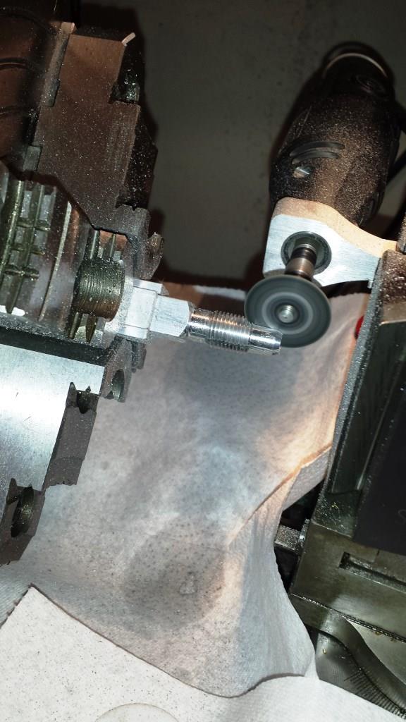
Lately on HMT there seems to be a theme of showing Dremel tool uses and below is another photo of a Dremel tool at work. It is cutting the slots for the clamping jaws with a 0.045” X 1.5” reinforced abrasive cutoff wheel. The abrasive wheel easily cuts through the aluminum but is partially consumed in the process and the dial indicator measuring the carriage travel is no longer valid for determining where to stop the cut. In this case a visual stop and don’t rely on depth stops or dial indicators whenever the diameter of the abrasive wheel is diminishing. Also, the lathe was protected from the cutoff wheel grit using paper towels and bulletin board magnets.
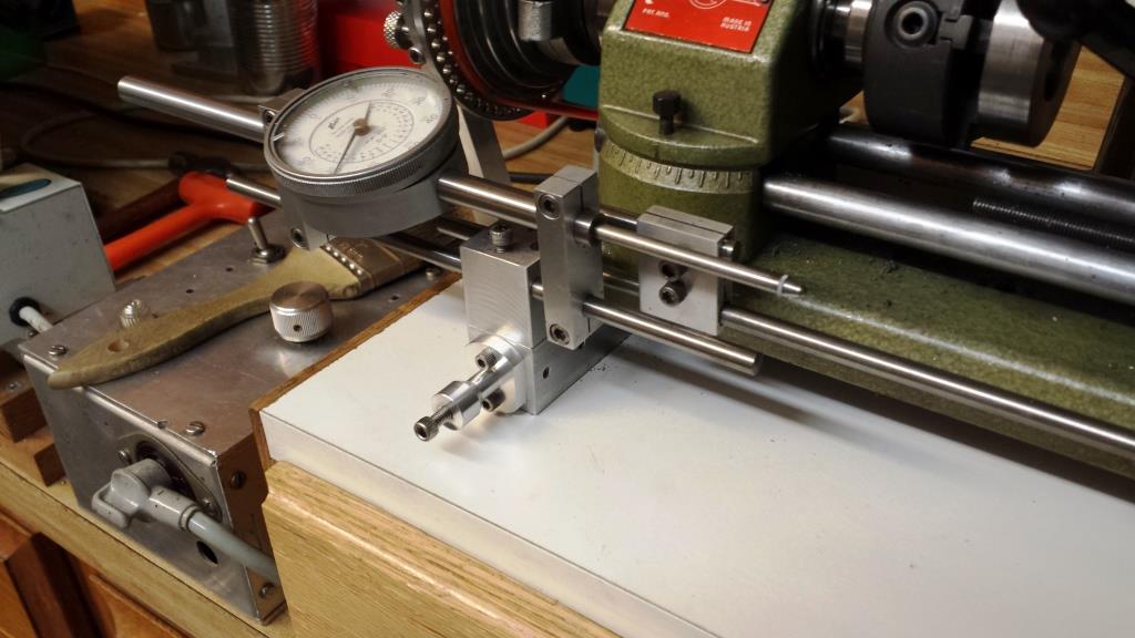
FYI - The Dial Indicator Adjustable Arm Extension is attached to the risers blocks I previously created for the Unimat lathe. At the time I anticipated adding more accessories to the lathe. I added pairs of 6-32 threaded holes to accommodate these future accessories. See the photos below. I plan to post more article about other special purpose parts that will be attached to the Unimat riser block including a power feed attachment.
Photo below shoes the pre-threaded 1" square lathe riser block for attaching lathe accessories.
Photo below shows the mounting bracket for the adjustable arm extension attached via 6-32 socket cap screws to the riser block.
Thank you for looking,
Paul Jones


 Reply With Quote

Bookmarks