
 LinkBack URL
 About LinkBacks


I have watched your video and I have a number of problems with it.
Oh, where to begin...
Your classification of regulators is reasonable, but the two groups - linear and switching are because they are very different in function, performance, and most importantly, efficiency. I didn't get the sense that you understood those differences.
Linear regulators are, as you describe, a voltage divider with a variably controlled resistance that regulates the output voltage. What is the variable resistance? Generally it is a transistor which is NOT controlled by some cartoon character. These regulators have fairly simple analog circuits and just because you can't explain how it works (here is how it works - it is a transistor that is controlled so that the transistor acts as a variable resistance and that control is a feedback loop from a voltage divider), you should not invent a cartoon function. This stuff is real science and engineering!!! If you can't explain it properly, don't use nonsense to wave your hands.
So, now that we know a linear regulator is a voltage divider, we can now understand why it is inefficient - there can be lots of power used in a voltage divider. Why - because a voltage divider is resistance and power for a resistor is resistance times current and the current is the current used by the curcuit being supplied power by the voltage regulator.
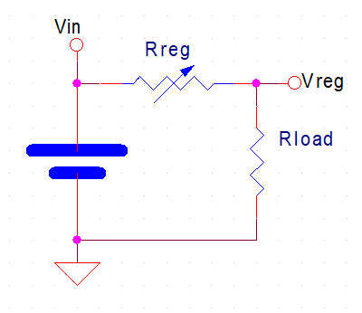
Here is the simple circuit for the regulator:
So - if want the regulator to supply 1A to Rload (that is the circuit we are powering) the regulator gets to disipate P=I*R = 1A * Rreg and the circuit disipates it's power of 1A * Rload. But wait - we have not said what Rreg is! Ah, true, but we know that the venerable 78xx series regulator (we will use the 7805 as an example) - can deliver the 1A we want and Vin will need to be at least 7.3v for a stable 5v Vreg. Now that we know Vin and Vreg we know the voltage across Rreg (2.3v minimum).
We have two formulas we use in figuring the circuits - Ohms Law (V=I*R) and the power law (P=V*I) :: if you remember any formulas, remember these two and you can, if you know any two of Voltage, Current, and Resistance, you can find the missing one and know the power.
Here is where the linear regulator's deficiency comes into play. That 7805, if we supplied it 7.3v and it was regulating 5v at 1A, that is 2.3W. If we don't have a 7.3v Vin, but rather a 9v source, that means the 7805 is disipating 4W - heatsink required.
Linear regulators are inefficient in that for 5W of delivered power (5v*1A), the regulator uses 4W (4v*1A) of power = 5W/9W = 55.5% efficiency.
Suppose you don't have 9v but rather you are working on something that uses 12v Lead Acid batteries (which are really 13.6v nominal and 14.4v charging) - now your 7805 would need to dump 9.4w ((14.4v-5v)*1A).
Linear regulators are fantastic in low power delivery applications because you can often get rid of the regulator power without heatsinks. Efficiency still is poor, but if you are dealing with 20mW of power to dump, that often can mean just some wider traces on the PCB.
A switching regulator can be, if designed correctly, 90+% efficient, sometimes over 95% efficient. No, I don't expect this video to go into that, but dismissing switching supplies as being "noisy" is absolute nonsense. Yes, that fake 555 switcher is nonsense and you labled it so, but just because you make an awful circuit, that doesn't mean all are awful. Irresponsible!!!
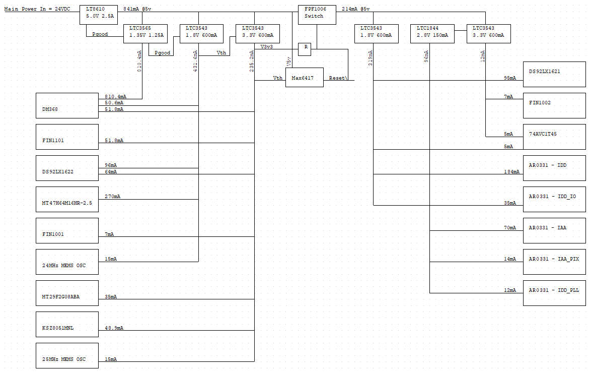
Here is a power diagram from a camera system I designed from 8 years ago (last thing I worked on before I retired).
It's kind of small to read, so click the image to expand. This is for a single camera module which consists of a processor board which compresses 2048x1536 video at 15fps and a separate camera board with the imager. The sytem captured panoramic video imagery with up to groups of 8 cameras per panoramic module. Very efficient switching supplies, 24v in to the module goes to 5v and then becomes 1.35v, 1.8v, and 3.3v for the processor and 1.8v, 2.8v, and 3.3v for the imager. This would not be possible at all with linear regulation.
In summary - Linear regulation - fine for low power consumption, fine for reference voltages (such as needed by an Analog to Digital converter (AtoD or AD)). Switching regulation - needed for higher power consumption, sometimes is troublesome when not enough load.
And in closing - all those wall warts that power products in your home and shop - they are switching supplies...

 Reply With Quote

Bookmarks