Free 186 More Best Homemade Tools eBook:  
Get 2,000+ tool plans, full site access, and more.

User Tag List

Results 1 to 10 of 10

Thread: Peaucellier-Lipkin linkage - GIF

  1. #1
    Content Editor
    Supporting Member
    Altair's Avatar
    Join Date
    Aug 2013
    Posts
    11,874
    Thanks
    1,361
    Thanked 29,659 Times in 9,850 Posts

    Peaucellier-Lipkin linkage - GIF

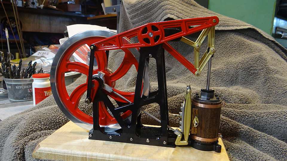
    Peaucellier-Lipkin linkage, the first planar linkage capable of transforming rotary motion into perfect straight-line motion.


    Previously:

    Rolling Ball Sculpture and Linkage Simulator
    Shaft linkage design for oppositely-rotating shafts - GIF
    Lever advancing ratchet mechanism - GIF
    Linear oscillating to rotational motion gear design - GIF
    Conjugate cams animation - GIF

    186 More Best Homemade Tools eBook
    Last edited by Jon; May 14, 2022 at 10:07 AM.

  2. The Following 6 Users Say Thank You to Altair For This Useful Post:

    cmarlow (May 14, 2022), EnginePaul (May 14, 2022), mwmkravchenko (May 15, 2022), nova_robotics (May 18, 2022), Philip Davies (May 15, 2022), rlm98253 (May 18, 2022)

  3. #2
    Supporting Member
    Join Date
    Oct 2018
    Posts
    242
    Thanks
    463
    Thanked 94 Times in 65 Posts
    OK, I think it is quite an elegant bit of mechanical art. Now I have to ask where you would use it?

    2000 Tool Plans

  4. #3
    Supporting Member Floradawg's Avatar
    Join Date
    Jul 2018
    Location
    Flora, MS
    Posts
    637
    Thanks
    573
    Thanked 131 Times in 98 Posts

    Floradawg's Tools
    Probably some engineer with a govt. grant to play with.
    Stupid is forever, ignorance can be fixed.

  5. #4

    Join Date
    Feb 2019
    Posts
    151
    Thanks
    62
    Thanked 99 Times in 55 Posts
    Quote Originally Posted by Floradawg View Post
    Probably some engineer with a govt. grant to play with.
    Probably not likely, it was invented in the 1860's. As for applications, a bit of info here (as much as I hate to quote wikipedia):

    "Until this invention, no planar method existed of converting exact straight-line motion to circular motion, without reference guideways. In 1864, all power came from steam engines, which had a piston moving in a straight-line up and down a cylinder. This piston needed to keep a good seal with the cylinder in order to retain the driving medium, and not lose energy efficiency due to leaks. The piston does this by remaining perpendicular to the axis of the cylinder, retaining its straight-line motion. Converting the straight-line motion of the piston into circular motion was of critical importance. Most, if not all, applications of these steam engines, were rotary.

    The mathematics of the Peaucellier–Lipkin linkage is directly related to the inversion of a circle."


    Most of these linkages were (I expect still are) developed as mathematical problems to be worked on and solved either to solve some particular real world problem or just for the sake of understanding the minute details of the world more deeply. Eventually lots of them trickle down into real world use. I don't pretend to understand much of the esoteric analysis behind stuff like this but find it all fascinating nonetheless. I have read a few books on the study of linkages and while I feel like I can follow much of what is being explained, the understanding leaves me pretty soon after I read it.


    https://en.wikipedia.org/wiki/Peauce...Lipkin_linkage

  6. The Following User Says Thank You to clavius For This Useful Post:

    nova_robotics (May 18, 2022)

  7. #5
    Supporting Member mklotz's Avatar
    Join Date
    Aug 2015
    Location
    LA, CA, USA
    Posts
    3,436
    Thanks
    357
    Thanked 6,391 Times in 2,118 Posts

    mklotz's Tools
    The linkage was typically used with early beam engines before the development of crossheads that would allow the piston connecting rod to always move linearly while directly driving the crankshaft.

    The photo shows the vertically oriented cylinder driving the end of the beam (which moves in an arc) via a Peaucellier linkage. The other end of the beam then drives a rotary power takeoff shaft via a conventional crank.

    These engines were operated at low speeds and the linkage helped extend their useful life to many decades at the expense of complexity and increased frictional losses.

    Peaucellier-Lipkin linkage - GIF-1589121521145.jpg
    ---
    Regards, Marv

    Home Shop Freeware
    https://www.myvirtualnetwork.com/mklotz

  8. The Following 2 Users Say Thank You to mklotz For This Useful Post:

    Frank S (May 15, 2022), rlm98253 (May 18, 2022)

  9. #6
    Supporting Member Floradawg's Avatar
    Join Date
    Jul 2018
    Location
    Flora, MS
    Posts
    637
    Thanks
    573
    Thanked 131 Times in 98 Posts

    Floradawg's Tools
    Quote Originally Posted by clavius View Post
    Probably not likely, it was invented in the 1860's. As for applications, a bit of info here (as much as I hate to quote wikipedia):

    "Until this invention, no planar method existed of converting exact straight-line motion to circular motion, without reference guideways. In 1864, all power came from steam engines, which had a piston moving in a straight-line up and down a cylinder. This piston needed to keep a good seal with the cylinder in order to retain the driving medium, and not lose energy efficiency due to leaks. The piston does this by remaining perpendicular to the axis of the cylinder, retaining its straight-line motion. Converting the straight-line motion of the piston into circular motion was of critical importance. Most, if not all, applications of these steam engines, were rotary.

    The mathematics of the Peaucellier–Lipkin linkage is directly related to the inversion of a circle."


    Most of these linkages were (I expect still are) developed as mathematical problems to be worked on and solved either to solve some particular real world problem or just for the sake of understanding the minute details of the world more deeply. Eventually lots of them trickle down into real world use. I don't pretend to understand much of the esoteric analysis behind stuff like this but find it all fascinating nonetheless. I have read a few books on the study of linkages and while I feel like I can follow much of what is being explained, the understanding leaves me pretty soon after I read it.


    https://en.wikipedia.org/wiki/Peauce...Lipkin_linkage
    I'm not disagreeing with you but there's a much simpler way to do it. Think of a steam locomotive. If you spin the drive wheel the piston rod will make a nice linear move.
    Stupid is forever, ignorance can be fixed.

  10. #7
    Supporting Member Hoosiersmoker's Avatar
    Join Date
    Mar 2018
    Posts
    1,572
    Thanks
    291
    Thanked 310 Times in 250 Posts
    It looks more like they're transferring a linear motion (no matter how it's achieved) to a perpendicular linear motion. The method here seems to start with an eccentric wheel trapped between two blocks (not exactly a locomotive motion?) to create the horizontal motion then the linkages that follow to create the vertical linear motion. Or am I missing something? The "wheel" actuation is pretty typical, so nothing new there, it's the following pantograph type linkages, with two fixed points running off of a gear and rack, that transfer the first horizontal linear motion to the perpendicular linear motion. This apparently 3d printed version has a lot of play in it that an actual application would not allow.
    "Divided We Stand, Together We Rise!" - (From "White Feather") - Marillion

  11. #8
    Supporting Member Floradawg's Avatar
    Join Date
    Jul 2018
    Location
    Flora, MS
    Posts
    637
    Thanks
    573
    Thanked 131 Times in 98 Posts

    Floradawg's Tools
    Quote Originally Posted by Hoosiersmoker View Post
    It looks more like they're transferring a linear motion (no matter how it's achieved) to a perpendicular linear motion. The method here seems to start with an eccentric wheel trapped between two blocks (not exactly a locomotive motion?) to create the horizontal motion then the linkages that follow to create the vertical linear motion. Or am I missing something? The "wheel" actuation is pretty typical, so nothing new there, it's the following pantograph type linkages, with two fixed points running off of a gear and rack, that transfer the first horizontal linear motion to the perpendicular linear motion. This apparently 3d printed version has a lot of play in it that an actual application would not allow.
    I'm guessing you didn't understand my point. If you want to design something that does a simple thing into something complicated then, Bob's your uncle, there it is. My point was it could be simpler. Also the locomotive idea with an added linkage at the end of the "cylinder rod" sort of L shaped turned cw 90 degrees with a swivel point at the convergence of the two straight parts of the L and another rod at the other end of the L would produce motion up and down, if that is what apparently is vitally important. There are many ways it could be done.
    Stupid is forever, ignorance can be fixed.

  12. #9
    Supporting Member mklotz's Avatar
    Join Date
    Aug 2015
    Location
    LA, CA, USA
    Posts
    3,436
    Thanks
    357
    Thanked 6,391 Times in 2,118 Posts

    mklotz's Tools
    Quote Originally Posted by Floradawg View Post
    I'm not disagreeing with you but there's a much simpler way to do it. Think of a steam locomotive. If you spin the drive wheel the piston rod will make a nice linear move.
    Yes the piston rod moves linearly. However, it drives a slider in the crosshead which also moves linearly. The link driving the rotating wheels connects to the slider, not the piston rod. The forces perpendicular to the motion of the piston are absorbed by the slider pushing against the crosshead. There is essentially no perpendicular force on the piston rod.

    It was the invention of the crosshead that allowed the piston to drive the crankshaft/loco wheel directly that eliminated the need for the overhead beam and the various linkages, Peaucellier included.
    ---
    Regards, Marv

    Home Shop Freeware
    https://www.myvirtualnetwork.com/mklotz

  13. The Following 2 Users Say Thank You to mklotz For This Useful Post:

    Frank S (May 16, 2022), rlm98253 (May 18, 2022)

  14. #10

    Join Date
    Feb 2019
    Posts
    151
    Thanks
    62
    Thanked 99 Times in 55 Posts
    Quote Originally Posted by Floradawg View Post
    I'm not disagreeing with you but there's a much simpler way to do it. Think of a steam locomotive. If you spin the drive wheel the piston rod will make a nice linear move.
    I do get what you are saying. I think the point in this instance is what is noted in the description: "converting exact straight-line motion to circular motion,without reference guideways.

    I think it's the lack of reference guideways that was the important point of this particular linkage, for an application like the beam engine that Marv K. posted.

    To your point, there is are much simpler ways to do this, but until crossheads came along this was one workable (if more complex) way to accomplish that conversion.


    186 More Best Homemade Tools eBook

Thread Information

Users Browsing this Thread

There are currently 1 users browsing this thread. (0 members and 1 guests)

Bookmarks

Posting Permissions

  • You may not post new threads
  • You may not post replies
  • You may not post attachments
  • You may not edit your posts
  •