Free 186 More Best Homemade Tools eBook:  
Get 2,000+ tool plans, full site access, and more.

User Tag List

Results 1 to 10 of 10

Thread: Electrical brake for AC motors

  1. #1
    Supporting Member 2gsg2_muc's Avatar
    Join Date
    Aug 2021
    Location
    Munich
    Posts
    25
    Thanks
    0
    Thanked 43 Times in 15 Posts

    2gsg2_muc's Tools

    Electrical brake for AC motors

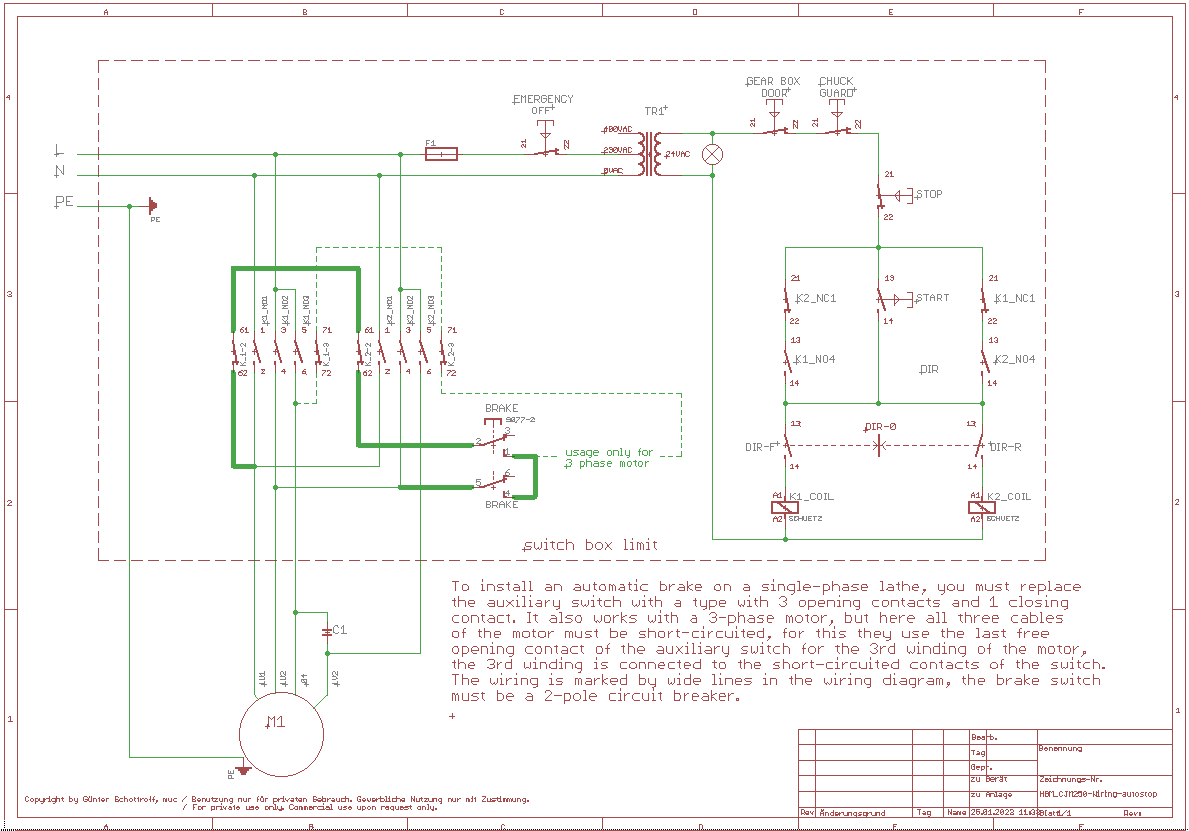
    When thread cutting on the lathe, it is easier if the motor can be braked automatically. This can be done simply by short-circuiting the windings by means of the counter electromotive force generated. For this purpose, the auxiliary switch of the contactor of the drive motor must have 2 free closing contacts. In the case of a single-phase motor, only one phase must be short-circuited via the make contacts of the contactors for both directions of rotation with the second phase via a 2-pole brake switch. With a 3-pole motor, the second phase must also be routed via the make contacts of the contactors, and the third phase is then connected to the short-circuited contacts of the brake switch. The wiring can be found in the wiring diagram. The required auxiliary contacts can be ordered from the contactor manufacturer. Since usually only 2-pole auxiliary switches are installed, these can simply be replaced with a 4-pole auxiliary switch with three make contacts and one break contact.


    Click image for larger version. 

Name:	Lathe-motor-brake.png 
Views:	1942 
Size:	42.1 KB 
ID:	44725

    186 More Best Homemade Tools eBook

  2. The Following 5 Users Say Thank You to 2gsg2_muc For This Useful Post:

    EnginePaul (Apr 11, 2023), Jon (Jan 26, 2023), nova_robotics (Feb 21, 2023), Scotty1 (Feb 11, 2023), uv8452 (Feb 26, 2023)

  3. #2
    Supporting Member 2gsg2_muc's Avatar
    Join Date
    Aug 2021
    Location
    Munich
    Posts
    25
    Thanks
    0
    Thanked 43 Times in 15 Posts

    2gsg2_muc's Tools

    schematic for easier understanding

    Prinzischaltpan der Motorbremse.
    Click image for larger version. 

Name:	2023-01-26_022515.png 
Views:	1746 
Size:	184.8 KB 
ID:	44736

    2000 Tool Plans

  4. The Following 3 Users Say Thank You to 2gsg2_muc For This Useful Post:

    nova_robotics (Feb 21, 2023), Scotty1 (Feb 21, 2023), uv8452 (Feb 26, 2023)

  5. #3
    Content Editor
    Supporting Member
    DIYer's Avatar
    Join Date
    Aug 2013
    Posts
    3,056
    Thanks
    772
    Thanked 1,850 Times in 1,652 Posts


    Thanks 2gsg2_muc! We've added your AC Motor Brake to our Electrical category,
    as well as to your builder page: 2gsg2_muc's Homemade Tools. Your receipt:


  6. #4
    Supporting Member 2gsg2_muc's Avatar
    Join Date
    Aug 2021
    Location
    Munich
    Posts
    25
    Thanks
    0
    Thanked 43 Times in 15 Posts

    2gsg2_muc's Tools

    Video How the Circuit is working

    The first switch is for the power supply, the second for baraking function

    [video] https://www.dropbox.com/s/0lm75yl98t...hort-.mp4?dl=0
    Last edited by 2gsg2_muc; Feb 11, 2023 at 03:44 PM.

  7. The Following User Says Thank You to 2gsg2_muc For This Useful Post:

    nova_robotics (Feb 21, 2023)

  8. #5
    Supporting Member 2gsg2_muc's Avatar
    Join Date
    Aug 2021
    Location
    Munich
    Posts
    25
    Thanks
    0
    Thanked 43 Times in 15 Posts

    2gsg2_muc's Tools
    Hello,

    now I want to show you how I installed the Aotostop at my CJM250 using shorting of the motor when threading. I made a little box with a limit switch, which can be slided over the lathe bed to adjust the sto point. The wiring is implementet to the regular stop switch of the lathe. it contains also two LED indicating the state of the motor. Green means the motor can be startet for threading, when the slide reaches the actuator of the switch it will stop the motor imdiately. The motor can be startet only in reverse direction again, to start a new turn for threading. t works exelent at a speed between 50 and 150 RPM. Do not forget to switch to autostop funktion bevore threading.

    Electrical brake for AC motors-autostop-controlbox.jpgElectrical brake for AC motors-autostopp-clear.jpgElectrical brake for AC motors-autostop-brake.jpg

  9. The Following 3 Users Say Thank You to 2gsg2_muc For This Useful Post:

    emu roo (Feb 21, 2023), nova_robotics (Feb 21, 2023), uv8452 (Feb 26, 2023)

  10. #6
    Supporting Member
    Join Date
    Sep 2018
    Posts
    2,123
    Thanks
    9,992
    Thanked 1,133 Times in 609 Posts

    nova_robotics's Tools
    Excellent work. You just gave me an idea with the box with the LEDs on it. What about using a hall effect sensor instead of a mechanical switch?

  11. #7
    Supporting Member 2gsg2_muc's Avatar
    Join Date
    Aug 2021
    Location
    Munich
    Posts
    25
    Thanks
    0
    Thanked 43 Times in 15 Posts

    2gsg2_muc's Tools
    I do not recomment a hall sensor underneaht a cutting tool, it may disturb your motor control system.

    Attached the circuit diagram of my CJM250
    Attached Files Attached Files
    Last edited by 2gsg2_muc; Feb 22, 2023 at 11:12 AM. Reason: adding scematic

  12. #8
    Supporting Member 2gsg2_muc's Avatar
    Join Date
    Aug 2021
    Location
    Munich
    Posts
    25
    Thanks
    0
    Thanked 43 Times in 15 Posts

    2gsg2_muc's Tools

    motor brake by short

    New improved basic circuit diagram.

    Click image for larger version. 

Name:	Motor brake basic ciruit diagram.gif 
Views:	1110 
Size:	38.8 KB 
ID:	45036
    Attached Files Attached Files
    Last edited by 2gsg2_muc; Feb 26, 2023 at 03:48 PM. Reason: Wrong PDF

  13. The Following 2 Users Say Thank You to 2gsg2_muc For This Useful Post:

    EnginePaul (Feb 27, 2023), kboy0076 (Feb 28, 2023)

  14. #9
    Supporting Member
    Join Date
    Oct 2019
    Location
    Germany
    Posts
    125
    Thanks
    457
    Thanked 100 Times in 36 Posts

    uv8452's Tools
    Right: Even I know (and own) 
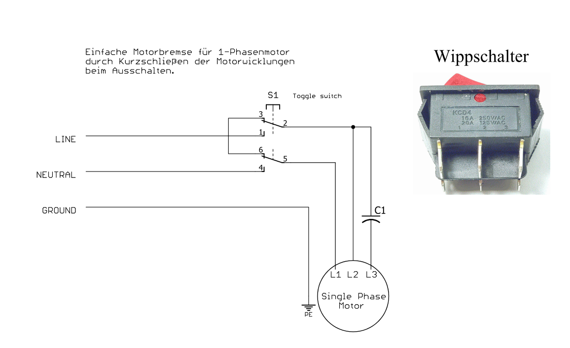
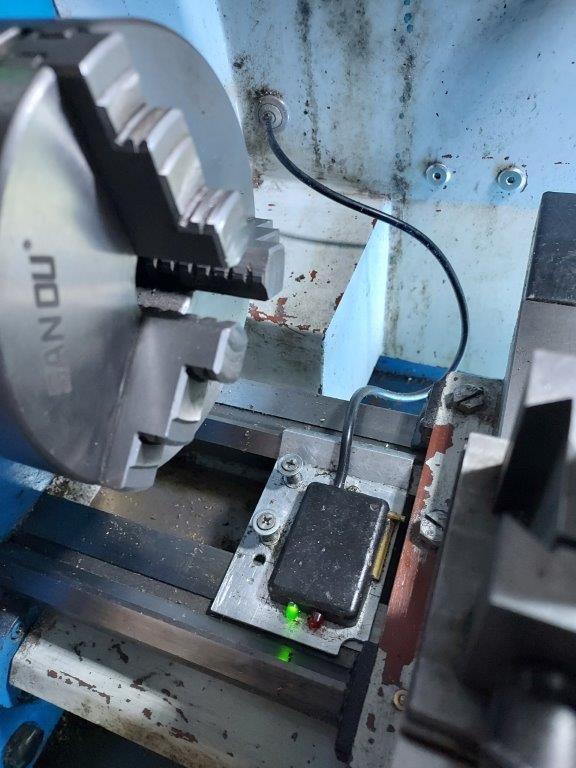
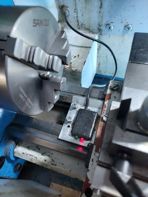
hermetically sealed switches I'd like something-in-a-closed-box. Inductive switch or reed switch?

  15. #10
    Supporting Member 2gsg2_muc's Avatar
    Join Date
    Aug 2021
    Location
    Munich
    Posts
    25
    Thanks
    0
    Thanked 43 Times in 15 Posts

    2gsg2_muc's Tools
    Hello uv8452
    what you need is a contactor which can handle the load of your motor. My picture shows a toggle switch, which must be installed in a box.


    186 More Best Homemade Tools eBook

  16. The Following User Says Thank You to 2gsg2_muc For This Useful Post:

    uv8452 (Feb 27, 2023)

Thread Information

Users Browsing this Thread

There are currently 1 users browsing this thread. (0 members and 1 guests)

Bookmarks

Posting Permissions

  • You may not post new threads
  • You may not post replies
  • You may not post attachments
  • You may not edit your posts
  •