2 Attachment(s)
Everyone needs a hardness tester.
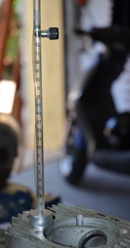
I needed a hardness tester to test the hardness of cylinder heads and other engine components.
Years ago, sales reps would give garages and reconditioning shops a simple tester based on the Shore rebound principle. I made a copy of those for myself but I was disappointed with it because it was too fast to get repeatable results by visual observation. I then made a more sophisticated version which replaced my poor old man's observational skills with electronics and an Arduino.
Then when preparing this post I saw how the use of a camera or smart phone could turn the original version into a really useful instrument. This multi-disciplinary post describes both versions. There is mechanical, electronic, programming and simple maths content but the original version only uses the mechanical, so do not be frightened off if electrons bring you out in a rash.
Attachment 38352 Attachment 38353 Click thumbnails for full size.
These really need to be seen in action so I prepared two videos, part 1 describes the mechanical stuff and discusses hardness testing in general and part 2 looks at the electronics (very simple).
However, video is not the best format in which to present schematics and programmes so I have also prepared a PDF with file. A PDF is not the best medium from which to lift the text of an Arduino programme so I also include that in this post directly, just copy and paste into your Arduino IDE.
Videos: https://youtu.be/oxT8Uqq88xM
and https://youtu.be/4ghW9RNKiDA
Watch part 1 before part 2.
Here is the PDF: https://diqn32j8nouaz.cloudfront.net...ess_tester.pdf
----------------------------------------------------
Here is the programme to upload to an Arduino Nano or other compatible micro.
#include <Wire.h> // Communications library
#include <LiquidCrystal_I2C.h> // Library for printing to display
LiquidCrystal_I2C lcd(0x27,20,4); // set the LCD address to 0x27 and a 20 x 4 display.
// Change these two constants to suit your own hardware implementation.
float s = 0.0049;
// Vertical constant distance between sensors in m.
float twoas = 0.1813;
// Constant 2as is used to correct velocity using 9.25 mm final drop after mean sensing.
void setup(){
lcd.init();
lcd.backlight();
lcd.clear();
lcd.setCursor(1,0);
lcd.print("Leeb");
lcd.setCursor(1,1);
lcd.print("Rockwell C");
lcd.setCursor(1,2);
lcd.print("Brinell");
lcd.setCursor(1,3);
lcd.print("Vickers");
pinMode(2, INPUT_PULLUP);
pinMode(3, INPUT_PULLUP);
myCalc();
}
unsigned long t[4], dt1, dt2;
float v1, v2 ;
uint16_t leeb, Rc, Brin, Vick;
void myCalc() {
// Get timings. This works better than using interrupts.
while (! digitalRead(2)) { }
t[0] = micros();
while (! digitalRead(3)) { }
t[1] = micros();
while (digitalRead(3)) { }
while (! digitalRead(3)) { }
t[2] = micros();
while (! digitalRead(2)) { }
t[3] = micros();
// Calculate time intervals
dt1 = t[1] - t[0];
dt2 = t[3] - t[2];
// Calculate and adjust drop & rebound velocities
v1 = (1000000*s)/dt1; v1 = sqrt(v1*v1 + twoas);
v2 = (1000000*s)/dt2; v2 = sqrt(v2*v2 + twoas);
// Calculate leeb hardness value and convert to other scales
leeb = (1000 * v2)/v1; // Leeb value
Rc = -0.000112211 * leeb*leeb + 0.2808769 * leeb - 93.83636; // HRC
Brin = 0.00237066 * leeb*leeb -1.646908 * leeb + 455.7088;
// Brinell
Vick = 0.00264169 * leeb*leeb -1.900271 * leeb + 519.8346;
// Vickers
myDisplay();
}
void myDisplay() {
if (leeb < 1000 && leeb > 0) {
if (leeb >= 950) {
lcd.setCursor(0,1); lcd.print("**High value** ");
}
else if (leeb < 400) {
lcd.setCursor(0,1); lcd.print("** Low value ** ");
}
if (leeb >= 400) { //Value when Rc = 0
lcd.setCursor(16, 1); lcd.print(Rc);
}
lcd.setCursor(15, 0); lcd.print(leeb);
lcd.setCursor(15, 2); lcd.print(Brin);
lcd.setCursor(15, 3); lcd.print(Vick);
}
else { // When !(leeb < 1000 && leeb > 0)
lcd.clear();
lcd.setCursor(0, 1); lcd.print("***** WARNING *****");
lcd.setCursor(0, 2); lcd.print("Value out of range.");
}
}
void loop() {
}
3 Attachment(s)
So I finally "got around to it..."
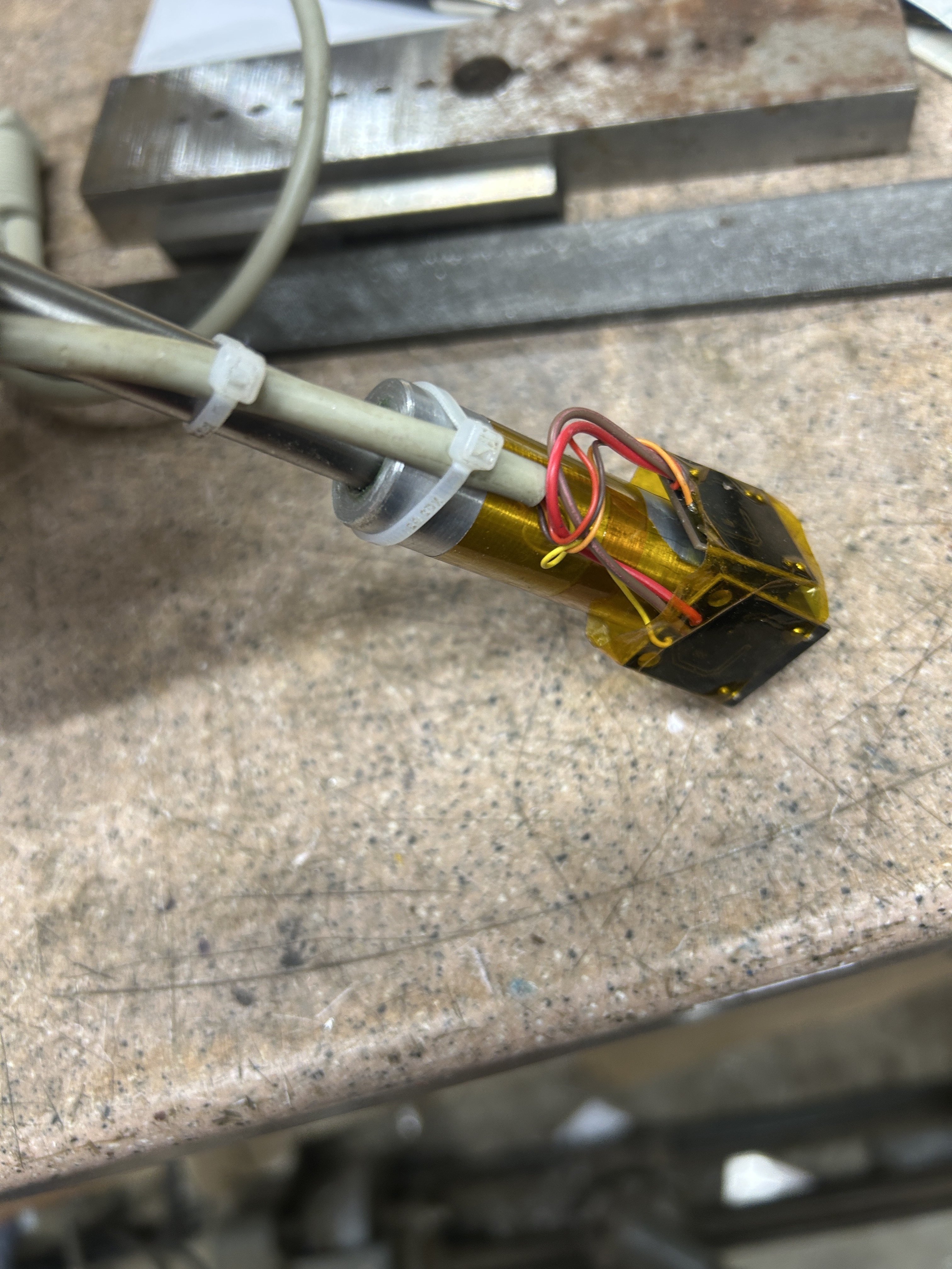
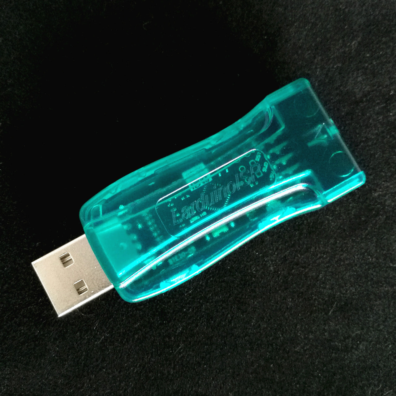
So after a few false starts and many distractions, I finally built myself a version of Tony's Leeb hardness tester. I deviated just slightly from his initial approach in that rather than using individual phototransistors and LED sources paired with the LM393 comparator, I purchased some premade slot photosensors (I think Tony mentions this as a possibility but did not have any on hand) that came mounted to a small PCB that includes a Schmidt trigger right on the board. So I only needed to supply them with 5Vdc and I get a nicely squared output. I think it cost about $8US for 5 of them from amazon. They were almost ideal sized for straddling the stainless tube I used. They ended up mounted like this:
Attachment 50225
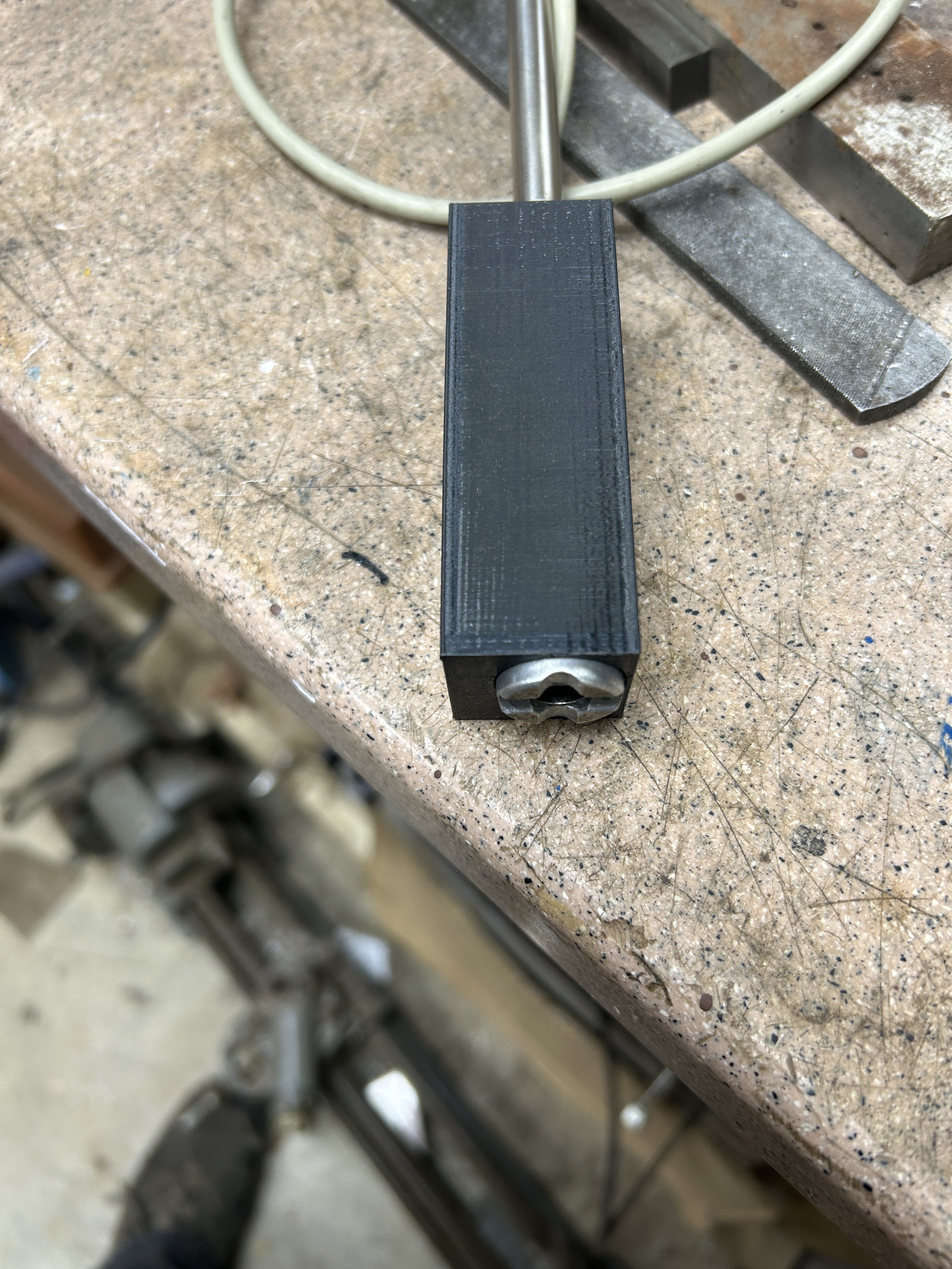
My son-in-law 3D printed this housing for me, it is a snug press fit onto the end of the part that the sensors are mounted on and protects the PC boards and wires nicely.
Attachment 50226
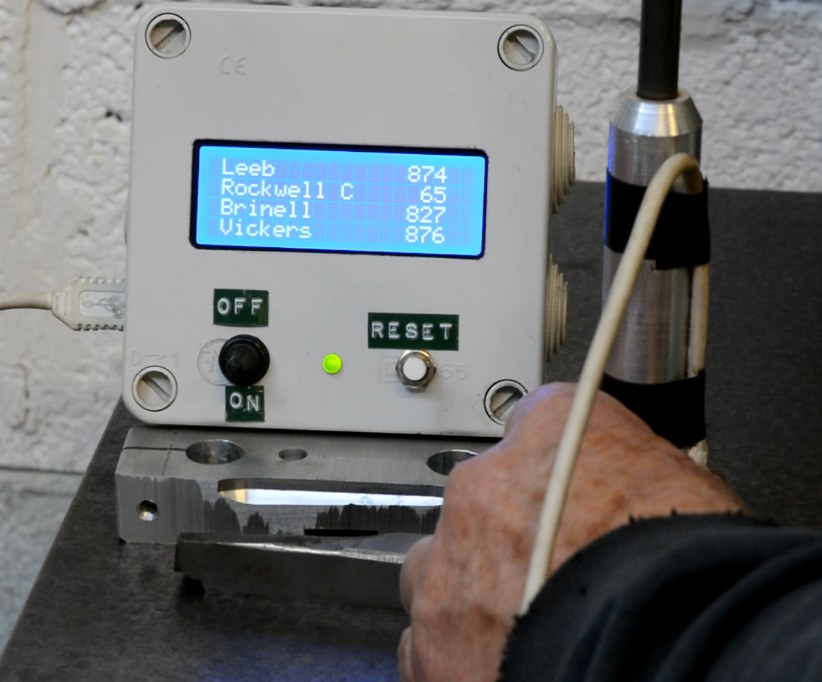
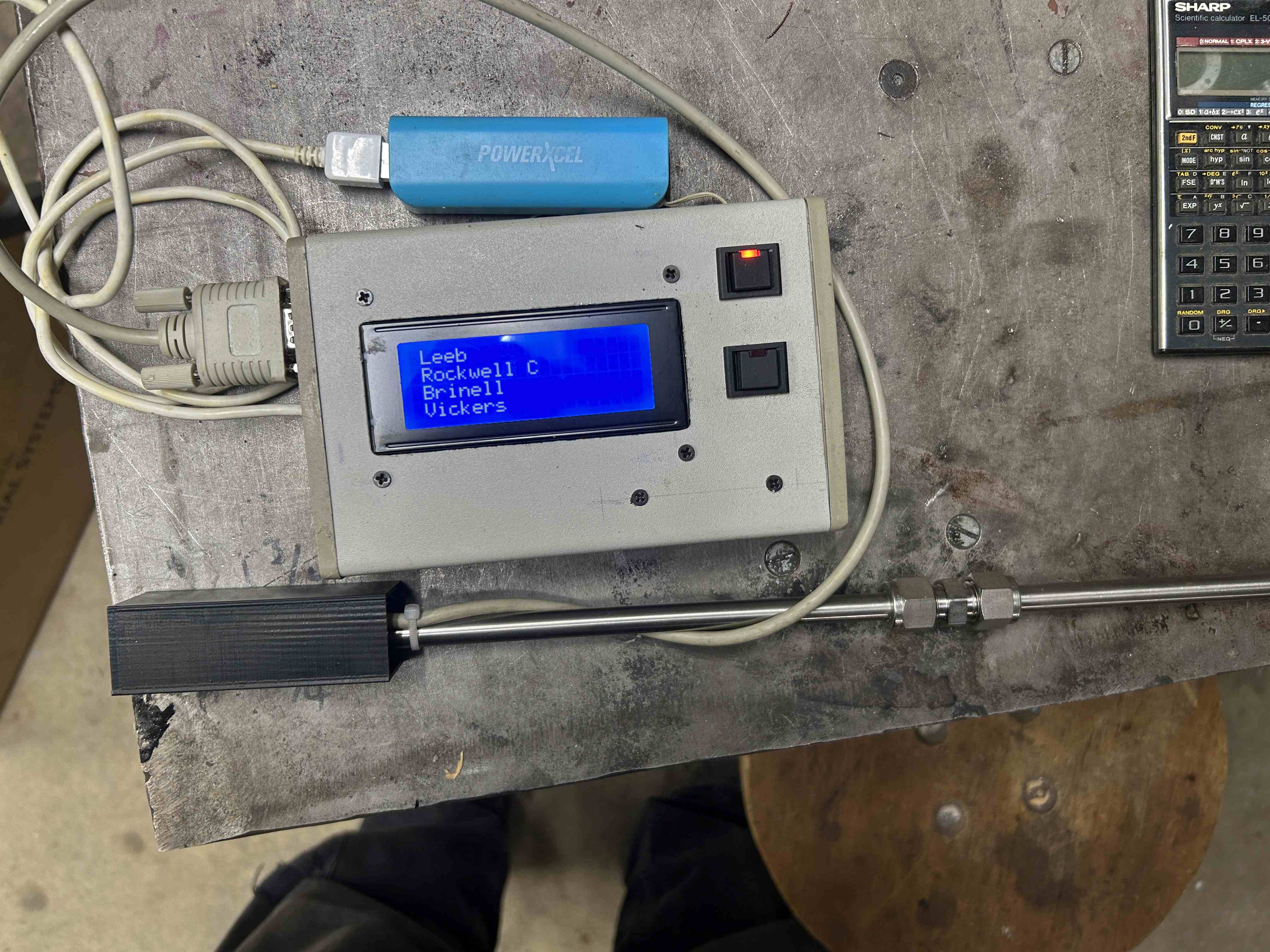
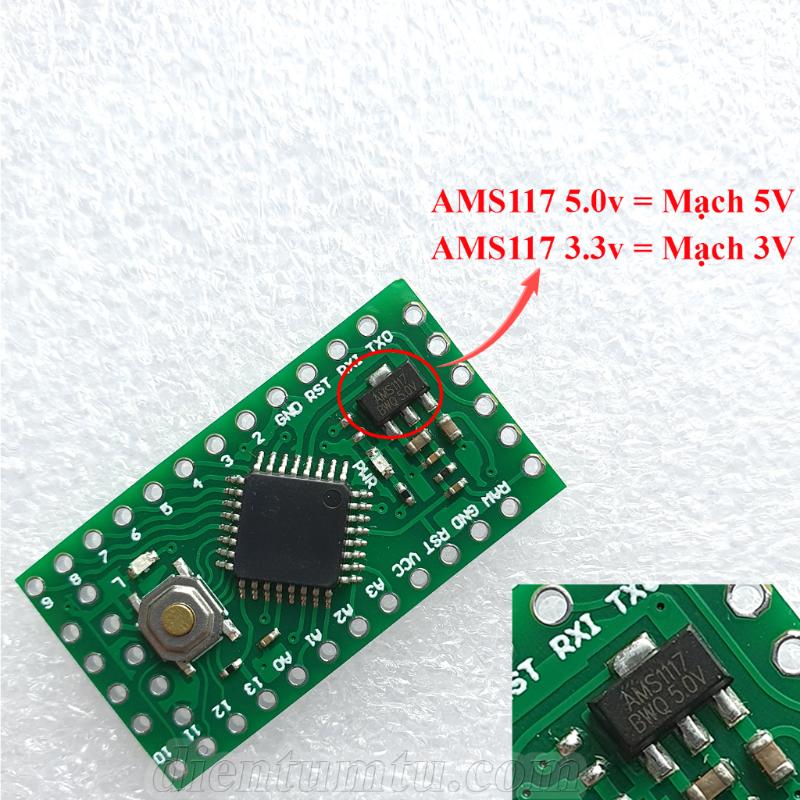
The electronics were put into the repurposed enclosure that used to hold some sort of barcode scanner interface that I intercepted before it hit the landfill. I used an Arduino Pro Nano as it takes up so little space and I had a few around. It power a USB cable so I can power it using either an AC USB charger/adapter or the small blue USB "power bank" you see in the picture for portable use. The double coupling in the drop tube allows me to take the tube down into two pieces for easier storage.
Attachment 50227
I use this all with a 1/4" steel ball. So far I seem to get pretty repeatable and reasonable results from it. I am working on getting a few sample steel pieces in various states of hardness that I hope to have tested on a calibrated Rockwell or other tester. That will give me some known values to compare against. In the meantime, I have every reason to believe that the results are plenty good for my, admittedly low spec, applications.
Thanks for all the work you did on this Tony and thanks especially for the through presntation on the theory and "how to do it" info you shared.
