Free 186 More Best Homemade Tools eBook:  
New: 300+ fresh build posts/day from 275 forums → BuildThreads.com

User Tag List

Results 1 to 10 of 10

Thread: Frankenlathe or E pluribus unem Wood Lathe

  1. #1
    Excelion's Avatar
    Join Date
    Aug 2017
    Posts
    6
    Thanks
    0
    Thanked 6 Times in 3 Posts

    Frankenlathe or E Pluribus Unem Wood Lathe

    I've always wanted my own lathe. My first experience was on an amazing old direct-drive Blount monster. I think you could spin half of a tree-trunk on it and wouldn't feel a wobble. So going with the idea that heavier is generally better, and not having $300 to dedicate to a "beginners level" wood lathe I'm making my own, and I feel like I may have found the right bunch to talk to about it.

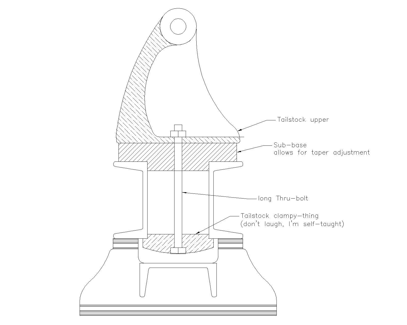
    The plan is to turn the c-channels sort of back-to-back, and get a longer bolt for the tailstock clamping bit with the idea being that thicker material will be closer to the point of impact when it comes to clamping, and more of the mass will be engaged if it comes to soaking up vibrations. Here is a 2d drawing of what I've got in mind:
    Frankenlathe or E pluribus unem Wood Lathe-3in-c-channel-bed-model.jpg
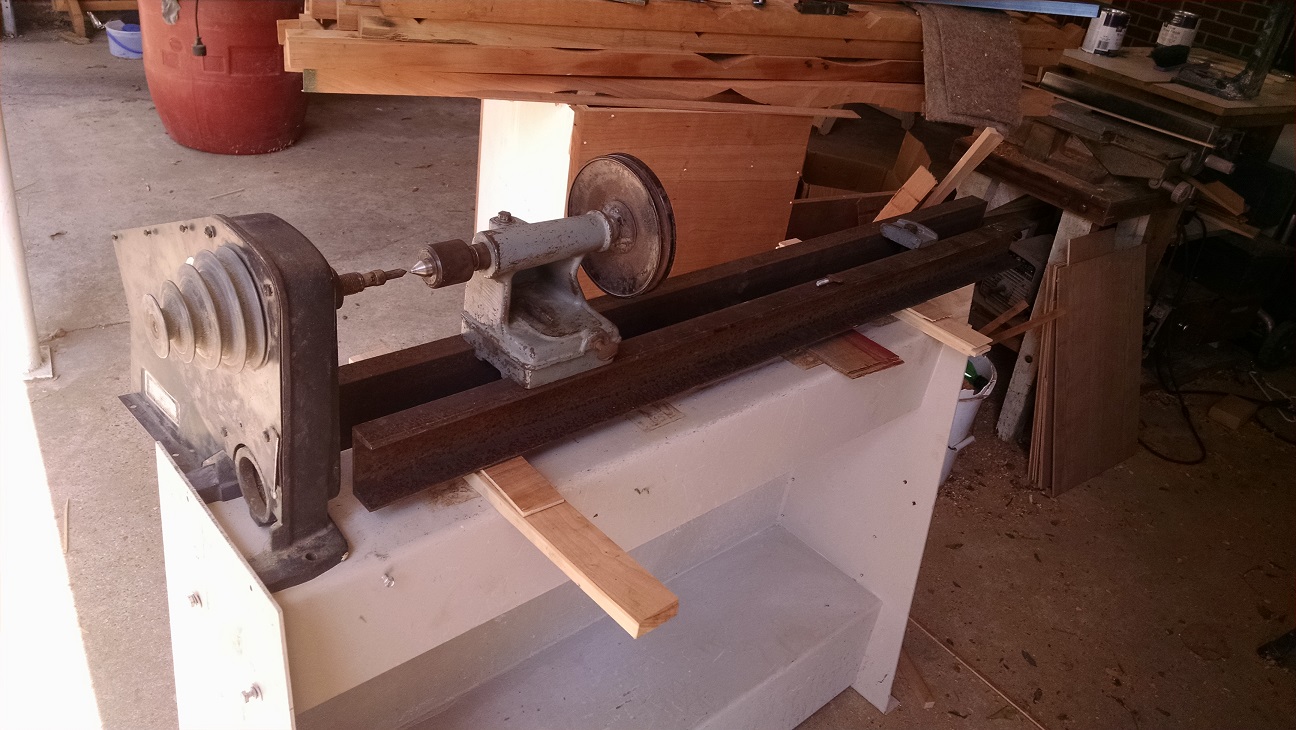
    This is about what it'll end up looking like, a bit taller, a bit less... rusty, but pretty much it.
    Frankenlathe or E pluribus unem Wood Lathe-lathemockup.jpg
    Craftsman headstock is a dumpster dive find (we'll see how that turns out... no pun intended!)
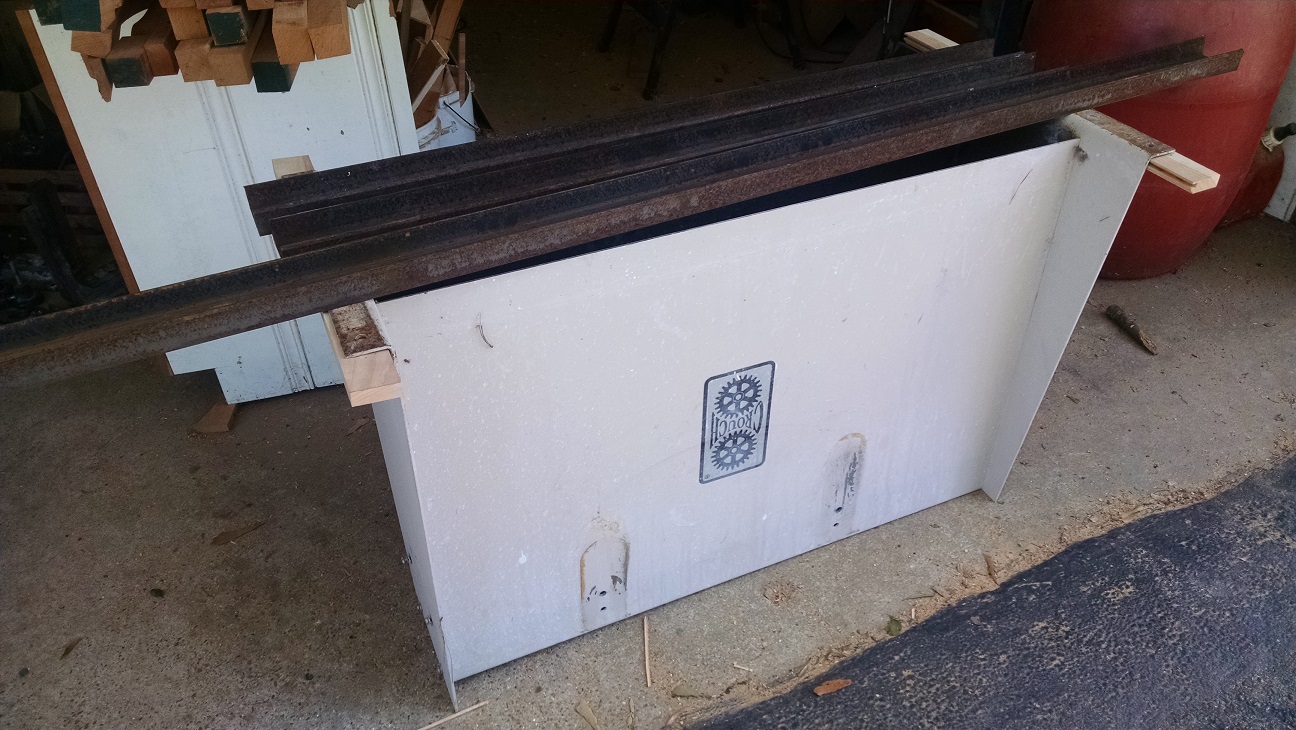
    Crouch industrial edge sander base was a cast-off from my employer (with lots of huge cast iron braces pictured below also
    Circa 1945 Walker-turner tailstock is an ebay purchase (came with the live center)

    Base w/c-channel:
    Frankenlathe or E pluribus unem Wood Lathe-lathebasecrouch.jpg

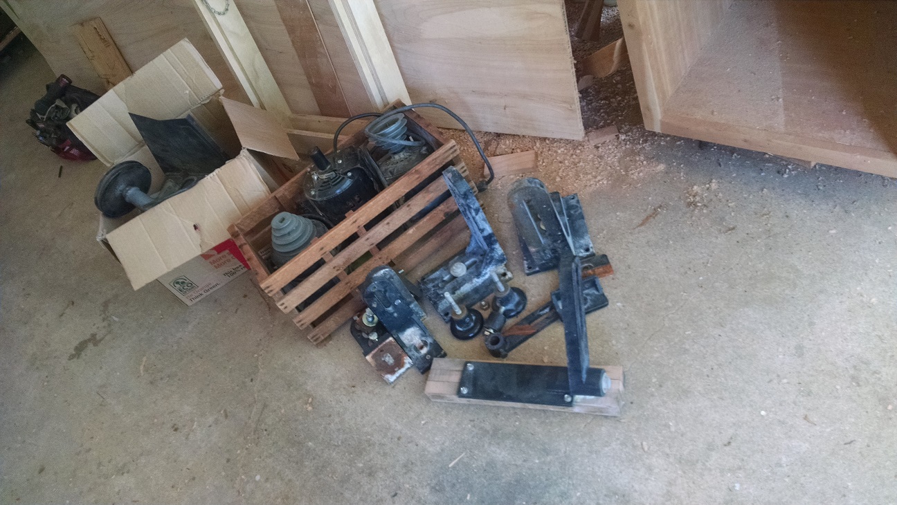
    Bits & Bobs that were attached to the base, and three 1/2 horse motors from the dumpster dive
    Frankenlathe or E pluribus unem Wood Lathe-lathebitsnbobs.jpg
    Last edited by Excelion; Aug 25, 2017 at 11:10 AM.

  2. The Following 4 Users Say Thank You to Excelion For This Useful Post:

    Jon (Aug 25, 2017), Paul Jones (Aug 26, 2017), Seedtick (Aug 25, 2017), Toolmaker51 (Aug 25, 2017)

  3. #2
    Supporting Member Toolmaker51's Avatar
    Join Date
    Feb 2016
    Location
    Midwest USA
    Posts
    5,355
    Thanks
    7,074
    Thanked 3,572 Times in 2,210 Posts

    Toolmaker51's Tools
    All the components are well suited to your lathe project. I'd warrant most suggestions (one immeasurable benefit of posting on HMT.net, besides we don't charge $.00!) might be;
    1. The Crouch base is a great foundation. Put 4 isolation/ leveling pads at the very corners [or extended somewhat lowering center of gravity] vs the C-channel, motor, and drive train. Base looks tapered, might become unstable at speed.
    2. Add a pillow block with longer shaft outboard the Craftsman headstock. That will generate better balance and rigidity at speed, and room for a jackshaft for a greatly expanded RPM range. Will allow lowering the motor for weight advantage, adjustment, and conventional length belts.
    3. 'We' will want to see what the spindle end accommodates in chucks, faceplates, and drive spurs. If there aren't any threads, the Shopsmith's use a .625 (5/8") diameter and setscrew flat - easily duplicated. In reality, threaded spindles are do-able too, but will take a little engineering; once again, duplicate a commercial design for desired tooling.
    4. The only dimensional challenge I see has two facets. That will be centerlines of tailstock and headstock coincide in two axis, especially in heights above the bed. Parallel [in reference to the bed length] can be 'swiveled' at the headstock or shimmed at the tailstock. One will influence method chosen to get the heights registered.
    5. Building your own allows planning additional features, to incorporate at convenient intervals.
    Sincerely,
    Toolmaker51
    ...we'll learn more by wandering than searching...

  4. #3
    Excelion's Avatar
    Join Date
    Aug 2017
    Posts
    6
    Thanks
    0
    Thanked 6 Times in 3 Posts
    Thanks Toolmaker51, the pillow block does sound like it might yield some good possibilities for, say conversion to a metal lathe at need. The Craftsman headstock pictured does have a threaded shaft, and has a #1 morse taper for a spur center or any other friction mounted doodad I should need. There will definately be a need for some shimmetry in my design, but I may be able to get a bit closer with some of the huge cast iron brackets that were on the base (which, in picture #2 is upside down btw, the wider end goes toward the pull of gravity).

    In the vein of conversion btw, do you or maybe this community at large know anything about how wide to make it on the outside, so it can be fitted fairly simply with a cross slide?

  5. #4
    Supporting Member Frank S's Avatar
    Join Date
    Aug 2015
    Location
    Peacock TX
    Posts
    12,617
    Thanks
    2,677
    Thanked 11,111 Times in 5,391 Posts

    Frank S's Tools
    Quote Originally Posted by Excelion View Post
    In the vein of conversion btw, do you or maybe this community at large know anything about how wide to make it on the outside, so it can be fitted fairly simply with a cross slide?
    In your case the width of the lathe ways is pretty much up to the builder. However components on hand such as the head and tail stock will determine a minimum.
    You did however mention the possibility of using it for turning metal. Wood lathes inherently make poor metal lathes but there are work arounds for this problem.
    #1 since it appears you will be using "C" channel for the frame or ways as they would be known on a metal lathe you did not mention the size you are planning to use nor the length you want to make the lathe or if you did I missed reading it.
    I will throw out a couple of very rough ideas as if I were the builder. first off I would calculate my desired center to center from face plate to live center, personally I would want to go with longer than I thought I would ever need or at least 4 ft at a minimum At that length though I would want at least 4" heavy "C" channel preferably 6" I would place them between 2 1/2 to 4" apart also I would mount my tail-stock a little unconventionally by clamping to the flanges from both sides and not use a center through bolt for this reason. This would allow me to place center bars made of 2" sq tubing between the channels in 2 or 3 places to insure they remained parallel and gain rigidity in case I ever wanted to turn it into a metal lathe.
    Similarly I would make a sliding carriage plate 1 1/2 times in width as the outside width of my flanges for much the same reasons,
    Now to turn the channel bed or frame into true ways I might use a ground and polished round on top of the flange nearest the work side of the lathe with a square bar on the opposite flange and 2 square bare on the underside My reason for this would be I could cut a "V" grove in my slide plate and I could shim clamp the underside plus the off side making it become a carriage. A gear rack could be added for traverse movement plus a lead screw could also be added which now entails making an apron to hang off the carriage plate but I am getting ahead of myself here
    As a wood lathe the carriage plate would only need a way of clamping in in place with a hole drilled in the center of it to mount the slotted tool post mount.
    Hope this gives you some ideas
    By the way you mentioned having 3 1/2 hp motors if they are all of the same size IE frame size RPM running amps and so forth you can parallel 2 or more together to give you more turning power as long as you use the same size pulleys on them to tie them together for instance if you mount 1 motor with a 4 grove pulley on it and find you need more power add a 2nd motor with exactly the same size pulley as one of the groves on the main motor make sure it is wired to run in the same direction and you will gain that amount of power based on the efficiency rating IE 85%
    Never try to tell me it can't be done
    When I have to paint I use KBS products

  6. #5
    Supporting Member Toolmaker51's Avatar
    Join Date
    Feb 2016
    Location
    Midwest USA
    Posts
    5,355
    Thanks
    7,074
    Thanked 3,572 Times in 2,210 Posts

    Toolmaker51's Tools
    Excelion's observation:
    Quote Originally Posted by Excelion View Post
    "... and I feel like I may have found the right bunch to talk to about it. (and) In the vein of conversion btw, do you or maybe this community at large know anything about how wide to make it on the outside, so it can be fitted fairly simply with a cross slide?
    re Outside width. I'd be tempted to start off simply sketching proportionately or full size, with the current headstock center height. That determines largest swing [part diameter]. Allow carriage size [across C-channels] sufficient travel so tool point traverses somewhat more than half that diameter.

    For actually turning metals, the challenge will be resolving the surface of the C-channel into decent sliding 'ways'. Further and IMHO, soundly designed metal lathes depend on three critical features. 1) Distance between inner and outer headstock bearings. 2) Positioning both planar axes of ways to centerline. 3) Width of carriage along the ways. Avatar displays my American Pacemaker, that IMNSHO [Not So Humble] exhibits those design factors taken to extremes.


    With utmost confidence and while not appointed to do so, vouch for this immeasurably broad community, and infinite depth as a creative resource. A few pictures, and/or some desired features ALWAYS get the ball rolling.
    We certainly appreciate how an individual progresses through a project, even when it stalls. The name is homemadetools [we abbreviate as HMT] isn't wrong or misleading; but the resources vary tremendously.
    Not one to quote Shakespeare often, but his line (inMeasure for Measure) states "Our doubts are traitors, and make us lose the good we oft might win, by fearing to attempt." typify our aficionados perfectly. Many operate in spare 6' x 10' areas, in compact but well equipped basements, others in full-fledged shops. All of those are advantageous compatriots; walls restrict project sizes not creativity or solutions. I'll be first to say, those smaller examples are nothing to sneeze at, doing brilliant work.

    And finally, your Gadsden serpent sports a defiant expression, toupee, neck beard, and hilarious warning. Is there a story behind it? Inquiring minds and all...
    Last edited by Toolmaker51; Aug 26, 2017 at 11:54 AM. Reason: triple f; format felt funny. Twice.
    Sincerely,
    Toolmaker51
    ...we'll learn more by wandering than searching...

  7. #6
    Excelion's Avatar
    Join Date
    Aug 2017
    Posts
    6
    Thanks
    0
    Thanked 6 Times in 3 Posts
    So I've got the 3" channel, and the tailstock needs a 2 1/2" gap. I've turned the C-s like these brackets ][ back to back. I'll be having the tops of them ground flat at a local tool & die shop, and where the flanges are the widest, I'll have them machined down to a designated width (v-edged or rounded or what have you to work with a hopefully existing carriage plate eventually if needed)

    Oh! And the Gadsden, I ran across it somewhere and, thought it was funny twist on a more serious sentiment. The head there is similar to a character from "The Emperor's New Groove." He's supposed to be an very young narcissistic Inca emperor that's been turned into a talking llama who, among other things doesn't like to be touched. I generally agree with the originator's sentiment as well, that I'm happy to peacefully coexist with most people, but stepping on me will not end well.
    Last edited by Excelion; Aug 28, 2017 at 07:53 AM. Reason: accidentally responding to two comments at once!

  8. #7
    Excelion's Avatar
    Join Date
    Aug 2017
    Posts
    6
    Thanks
    0
    Thanked 6 Times in 3 Posts
    Thanks for the insight on the motors, I was hoping to be able to do something to boost the power for bigger jobs. Do you think they'd work in place of reduction pulleys on a jack shaft? I know metal is turned at much slower speeds, and that's one of the ways I'd thought to do it.

    The C-channel size was already determined (and free btw), it's 3 x 1 3/8 x 3/16, and I plan on a 48" length (before tailstock, and planned to leave a gap between the ways and headstock body) Thanks, that does provide some food for thought, but I've never turned metal, so many aspects of the differences are new and mysterious to me. My question regarding the width of the ways really tends to what sizes would work with an existing carriage plate, and that I've no idea about.

  9. #8
    Supporting Member Frank S's Avatar
    Join Date
    Aug 2015
    Location
    Peacock TX
    Posts
    12,617
    Thanks
    2,677
    Thanked 11,111 Times in 5,391 Posts

    Frank S's Tools
    How you couple the motors doesn't matter as long as the pulleys are the same diameter on the motors leading to 2 pulleys which must be paired in size as well this may be 1 of a jack shaft with you step pulleys on the other end you could set the motors up in a triangle use a single belt to connect the motors to a single pulley on the jack shaft not my favorite arrangement but do-able You can also couple the motors shaft to shaft using a flex coupling with a pulley on one of them this would mean that 1 motor would need to be clockwise and the other anti clockwise if 1 of the motors has a double ended output shaft the other may be coupled to that with the pulley on the other end. You can pair 2 or motors together by just about any means available. I've worked on industrial applications where there might be 2 to 6 motors all driving a common article such as a long conveyor belt where they would be placed all along the length. and on oil drill rigs where up to 4 or 6 sometimes as many as 10 motors might be used compounded together by a huge gear box having several 1000 HP output
    Never try to tell me it can't be done
    When I have to paint I use KBS products

  10. #9
    Supporting Member Toolmaker51's Avatar
    Join Date
    Feb 2016
    Location
    Midwest USA
    Posts
    5,355
    Thanks
    7,074
    Thanked 3,572 Times in 2,210 Posts

    Toolmaker51's Tools
    Talking llamas with a narrow privacy zone. LOL Unaware of an Emperor's Grooves, new or old, but the story line is funny.

    I'm not sure what form a "existing carriage plate" might be. The ground tops are a good, nearly essential start. Machining the C-channel edges won't offer much torsional resistance from binding or establishing a running fit.
    I'm thinking commercially made 'LINEAR GUIDES' offer the best alignment and actual running surface with ground cylindrical rods; they bolt to flat surfaces quick and easy. The guides themselves operate something like recirculating ball-bearings in a steering box, but travel over the rods, mount much like a pillow block. Underneath the carriage plate, 4 blocks will establish uniform planes to the centerline and work well. Blocks can be spaced at widths desired. Another set above can be the cross-slide. These work so well, many commercial CNC machines use them instead of traditional ground surfaces.
    Lead screws and crank handle will control movements. We call those axes of movement X, Y, & Z, in conventional machinery, tooling and additional movements have other addresses. Here's a link.....
    https://www.google.com/search?q=lath...utf-8&oe=utf-8
    Substitute 'mill' for lathe to compare. They look different but aren't, just the machine orientation changes, ie spindles always the Z.

    Taking the slides assembled height will be a important consideration, to preserve decent turning capacity. The carriage is not as flexible in height as what can be done attaching the headstock and tail stock. Good design gets the carriage and crosslide low to their sliding surfaces for rigid stable platform. Simple triangulation, rather like center of gravity, why a GT40 out handles a tall four wheeler.

    A sketch even in rough scale and calculator makes this easy. Establish a 'datum' or reference, the ground channels are a natural. Add dimensions found in the specifications for items chosen to that reference, really for the entire build. Everything can locate + or - the datum. It isn't unusual to get "take-offs"; dimensions or proportions from a photo and scale them to similar project so and so.

    Don't hesitate with questions of any kind. I truly enjoy writing descriptions to help other visualize their answer. We are opinionated by various means of experience, but of the sites I frequent, these people are the bomb, and great community. I've been here about 18 months, remain stunned by various contributions.
    Not self-righteous, armchair engineers, or deep-pocket posers misleading hordes of unsuspecting novices.
    Not one.
    Last edited by Toolmaker51; Aug 28, 2017 at 10:00 AM.
    Sincerely,
    Toolmaker51
    ...we'll learn more by wandering than searching...

  11. #10
    Excelion's Avatar
    Join Date
    Aug 2017
    Posts
    6
    Thanks
    0
    Thanked 6 Times in 3 Posts
    Thanks guys for the advise and encouragement. I'm currently finishing up some butcher-block countertops in my kitchen, but after that I'll create a new tool post for the updates on this machine. With a well this deep of experience and support, I'm sure it'll come out great! Thanks again!


    2,500+ Tool Plans

  12. The Following User Says Thank You to Excelion For This Useful Post:

    Toolmaker51 (Sep 6, 2017)

Thread Information

Users Browsing this Thread

There are currently 1 users browsing this thread. (0 members and 1 guests)

Bookmarks

Posting Permissions

  • You may not post new threads
  • You may not post replies
  • You may not post attachments
  • You may not edit your posts
  •