
 LinkBack URL
 About LinkBacks


Hi!
I'm a newbie of this forum
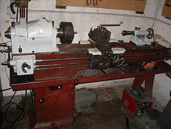
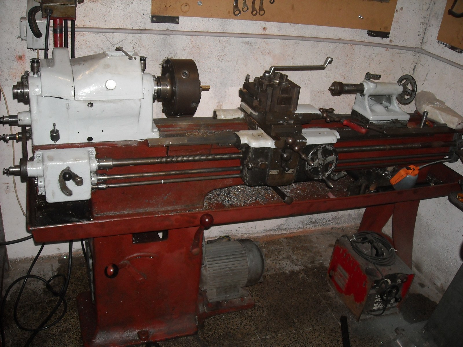
Some weeks ago i fixed my old lathe, changed bearings, restored a shaft for automatic, and buyed some gears for threading. Hardware store in Italy are similar to chinese store, same poor quality and common tools for Diyers sold at higher prices, the bigger is the shop the lower is the quality. Industrial suppliers have very good brands and tools, but they don't sell at single people, and if they sell the price is high as hell. At this time i have troubles finding used good tools. Surfing on internet i found on aliexpress some chinese indexable tool with insert, ( 40\50 $ one tool + 10 insert ) but i don't know if they are good or not.
I see in this forum some really interesting post of very skilled people, i'd like to ask some advice or tips and tricks for create internal (and maybe external) threading tools for lathe. I'm not too skilled in grinding tools, i'd like to create something sharps for threading aluminum and steel ( not inox ).
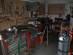
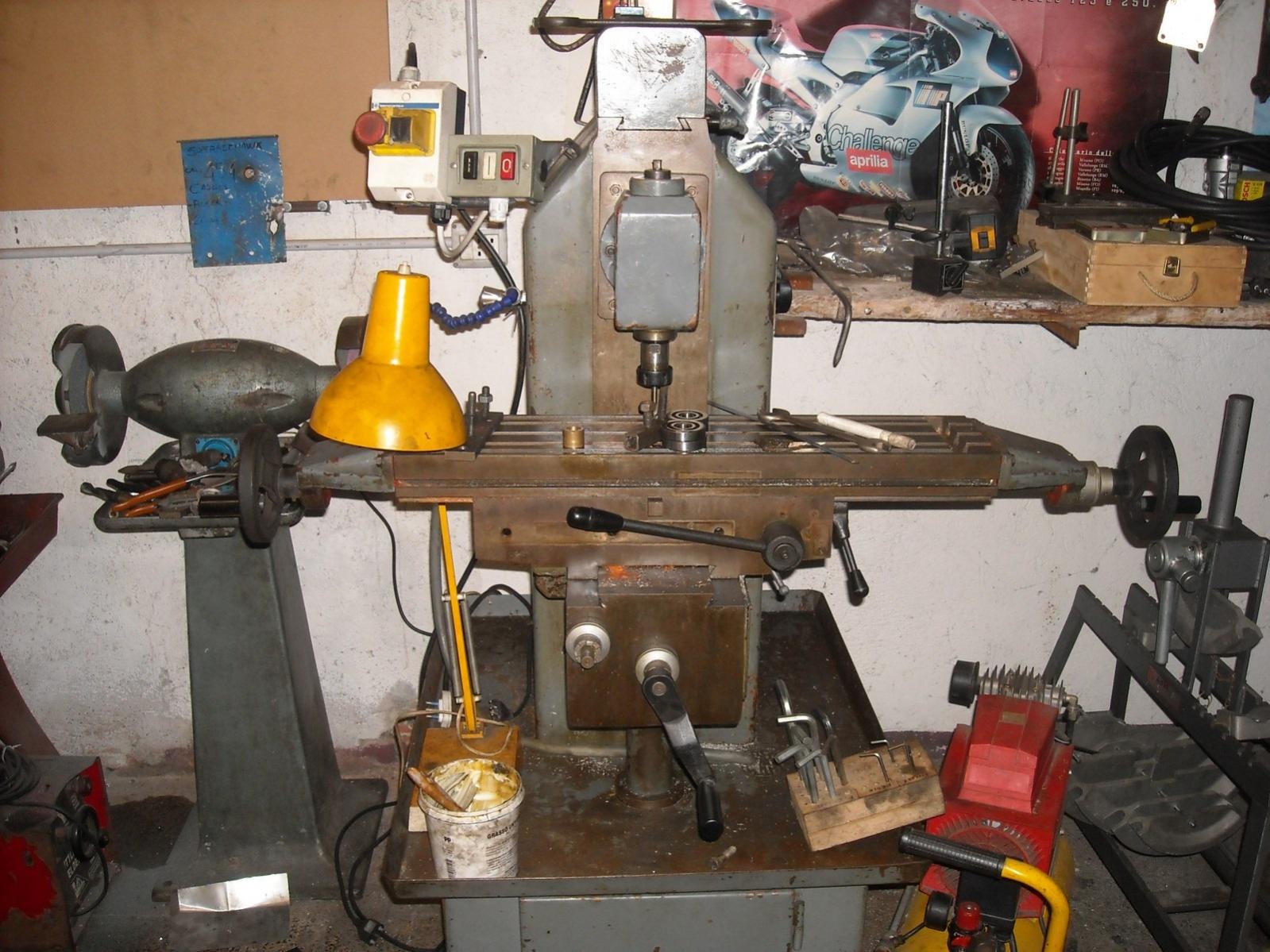
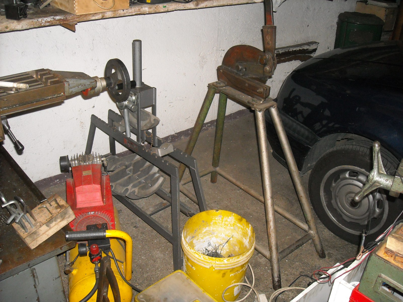
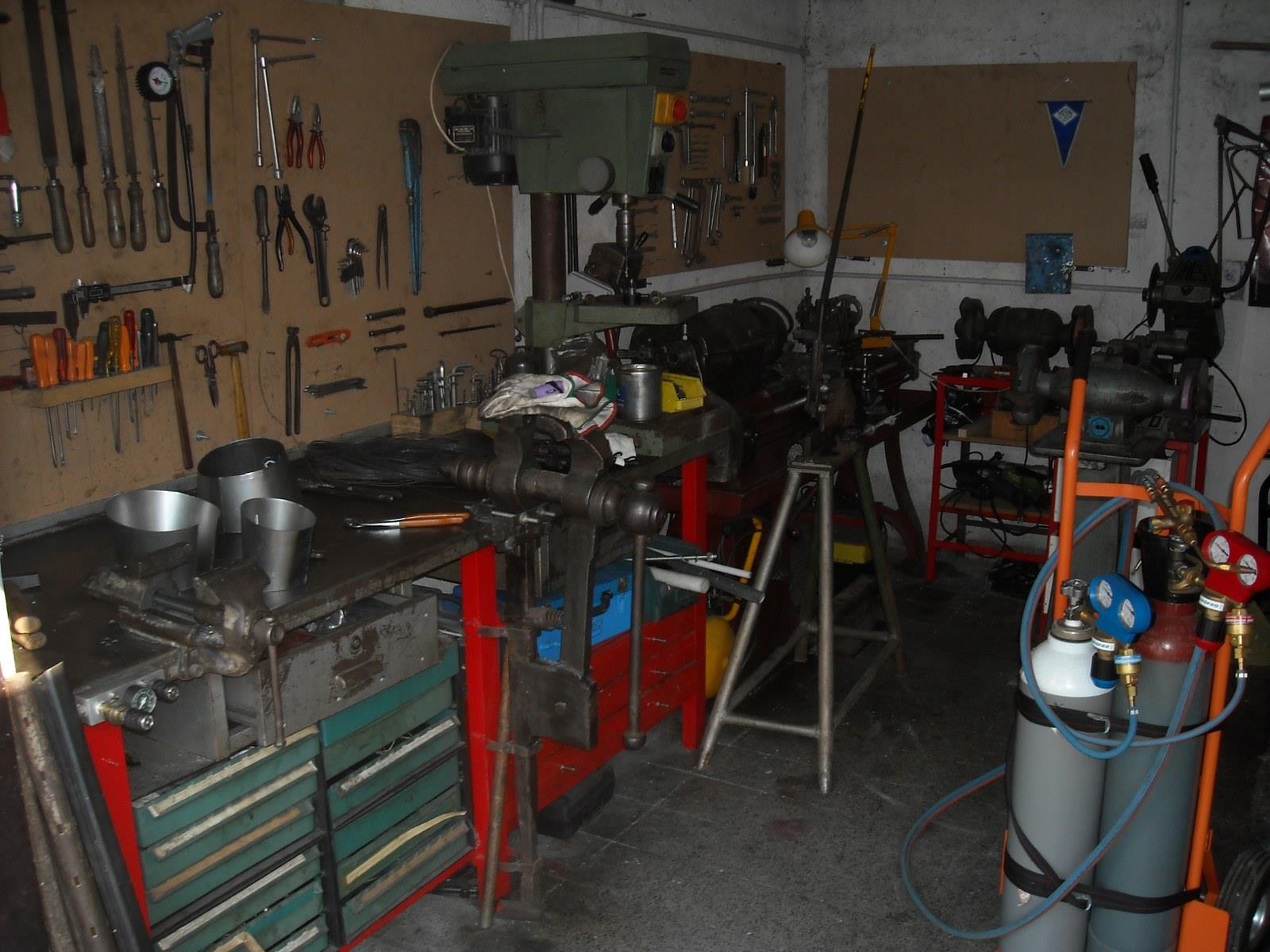
I post some photos of my little box with tools, i got lathe, cst milling machine, tube and plate bender , electric saw slow blade (sorry i don't know the eng name, in italian is "troncatrice a disco lento" with steel blade with short theets). transformer ac old welder and oxy-acetylene torch ( 40-500 lt/h and cutting torch )
Thanks in advance for an answer
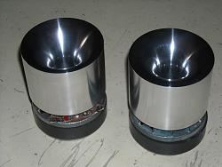
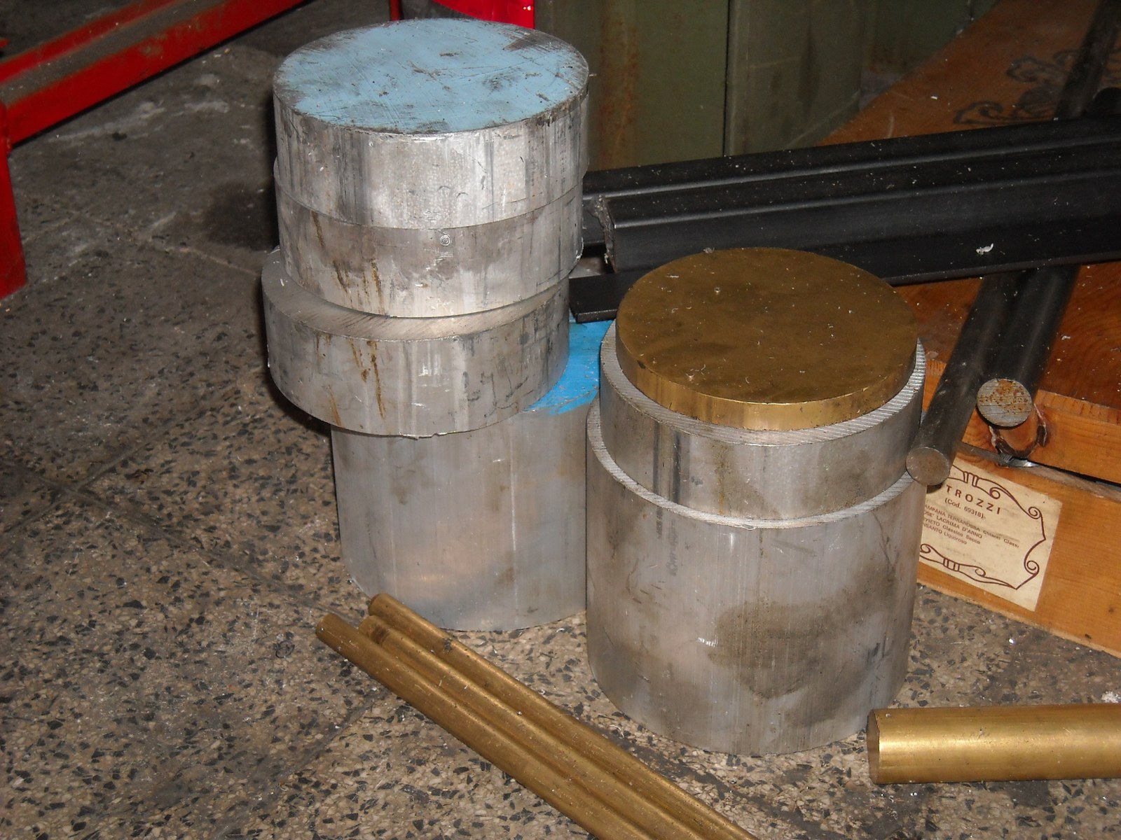
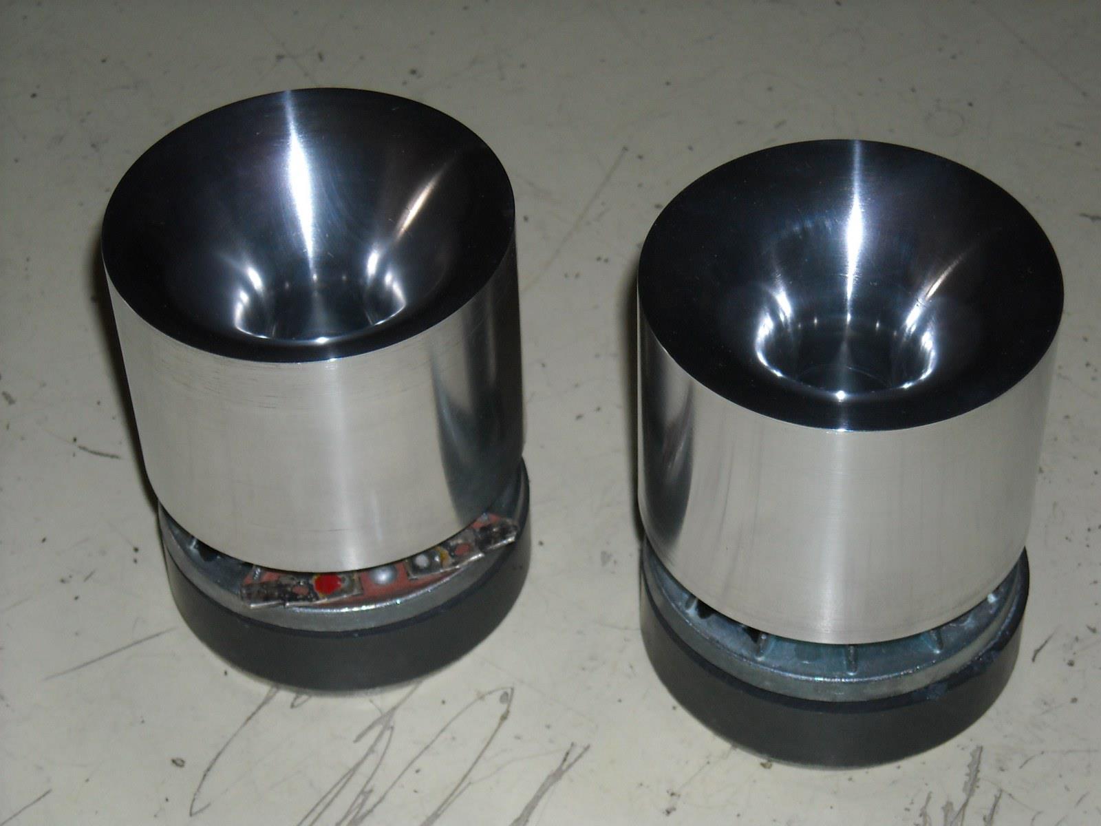
Ps: my next project is to make a pair of aluminum horn similar tothe last photo, but bigger (130mm - 5" dia), i need threading the horn and the flange attached to driver.
Saluti
Stefano


 Reply With Quote

Bookmarks