Free 186 More Best Homemade Tools eBook:  
Get 2,000+ tool plans, full site access, and more.

User Tag List

Results 1 to 5 of 5

Thread: Headstock fatigue rupture prevention

  1. #1
    Claudio HG's Avatar
    Join Date
    Sep 2019
    Location
    Venetian Alps, EU
    Posts
    107
    Thanks
    28
    Thanked 173 Times in 48 Posts

    Claudio HG's Tools

    Question Headstock fatigue rupture prevention

    Hello guys, after having posted my latest video on the spindle for my lathe I had a guy who pointed out that for him the thickness of the collar clamps that hold the spindle in the headstock are too thin and would break catastrophically when in use with off-center parts held in the jaws of the chuck. I did some calculations when I designed the part and I considered this problem, however he put me a doubt and I re-checked everything again because, you know, "safety is the number one priaoairhity" as CreazyRussianHacker would have said
    So, I post here my review of this thing to ask for opinions and let you catch any flaw in my calculations, if any.
    To see the video, go to my YT channel (be sure to click the "videos" section.
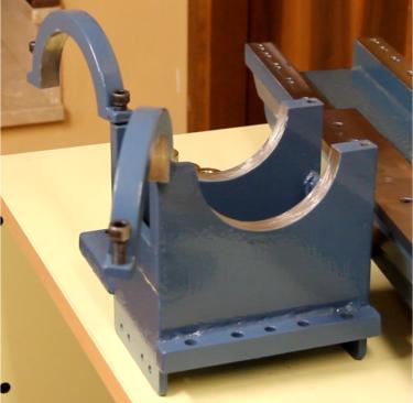
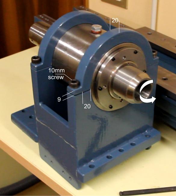
    Here some pictures of the headstock and the spindle, with dimensions:
    Headstock fatigue rupture prevention-pic2.jpg Headstock fatigue rupture prevention-pic3.jpg

    Headstock fatigue rupture prevention-pic1.jpg

    The collet clamps are made out by cutting with a plasma torch the part from a single 20mm sheet of mild steel. There are no weldings, it is a monolitic piece of steel.

    My calculations was the following:
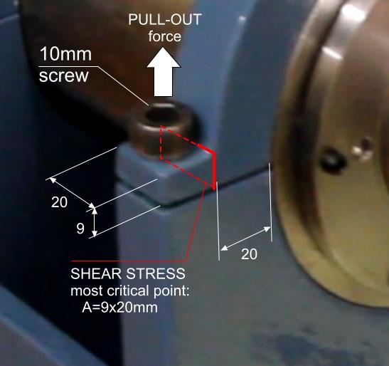
    - static shear stress, for mild steel is about 240MPa (approx. 60% of the UTS), on a area of 9x20mm is 180sqmm (the smallest area, hence the most critical point, of one side of the collet, see last figure) giving a 240 * 180 = 43200N (or 4400 Kg of equivalent force, 9700lbs) of force required to make the metal yield.
    - the bolts however should be the most critical point, as it has a much smaller area and for the M10 screw have an ultimate minimum load of 24400N (conservatively picked for mild steel cold threaded) which has an equivalent force of 2487Kg (5483lbs).
    (i.e. see here: https://www.engineeringtoolbox.com/m...ds-d_2026.html)

    So to tear apart one side of a clamp an equivalent force of more than 2400Kg should be exerted.
    The real problem however lies on the fatigue limit that could lead to a failure after a given number of cycles.
    In fact, suppose a part is kept in the jaws of the chuck and in rotation, this will generate an oscillating force against the clamps, with an average force of zero, that could cause a failure due to fatigue.
    This could be particularly true in the case a micro-crack or defect in the metal act as a trigger to start a major crack that grows and propagates deeply into the metal at each load cycle.

    Reading the literature on the topic I've found that typical mild steel with no micro-cracks or defects fails after a progressively higher number of cycles as the cyclic load is reduced, up to a point where even after a huge number of light load cycles it would never fail.
    This is point is at a ratio of about 1/3 to 1/4 of the ultimate shear stress.

    Using a safety ratio of 1/5 with my data above would lead to a maximum force of 4880N or equivalent force of 497Kg (1096lbs).
    This means that the case of an unbalanced part in rotation kept by the jaws of the chuck would cause a centrifugal force of max 497Kg.

    So that was my final assessment: Since the whole lathe would end up weighing around 200Kg (yes, it is a mini lathe despite the apparence of the spindle that is large only because I wanted to have a relatively larger hollow shaft), if a part, with a certain mass and spinning at a given speed, were to make an equivalent centrifugal force larger than 200Kg (250Kg if we add a generous weight of the bench) the whole lathe and bench would fly away well before having the risk of failure of the clamps.

    I have discussed the thing with a friend who happens to be a mechanical engineer and he gave me a confirmation of my assesment, yet I shared this with you to hear other's point of view that might spot overlooked mistakes.
    So, any thought is welcome. Thank you.

    Cheers, Claudio.

    186 More Best Homemade Tools eBook

  2. The Following 2 Users Say Thank You to Claudio HG For This Useful Post:

    DIYSwede (Nov 30, 2019), Jon (Nov 27, 2019)

  3. #2
    Supporting Member madokie's Avatar
    Join Date
    Oct 2017
    Posts
    165
    Thanks
    1
    Thanked 53 Times in 46 Posts
    railroad engineer it ...figure out what it should be,with a extra load factor,, then add 30% ...it will never fail then LOL.. i would also add shoulders of some kind to keep the top clamp from moving in different directions,both sideways and up and down, movement will cause cracking and failure..the more bolts clamping ,the better,anything to stop movement ..u could connect the top clamps , with a bar,or two,bolted to both..increase the size of the clamps where the bolts go in, they look too thin too me,(9mm?? i would double that,even if i had to buy a counter sink tool to get the bolt in)) better too much than too little..i didnt see anything to locate the clamp, just the 10mm bolt,which is not for locating parts,,add a dowel pin 4mm,1/4,, to keep clamp in place ,bolt just holds clamp down then,,has stress in only one direcetion..

    2000 Tool Plans
    Last edited by madokie; Nov 28, 2019 at 08:23 PM.

  4. #3
    Claudio HG's Avatar
    Join Date
    Sep 2019
    Location
    Venetian Alps, EU
    Posts
    107
    Thanks
    28
    Thanked 173 Times in 48 Posts

    Claudio HG's Tools
    Thanks for the reply. The clamps have no reasons to move sideways because the spindle have locating pins (not visible in the picture) that lock it in the spindle holder. The only way the spindle can move is upward. Why do you think 9mm is too thin? Did you find a mistake in my math?

  5. #4
    Supporting Member madokie's Avatar
    Join Date
    Oct 2017
    Posts
    165
    Thanks
    1
    Thanked 53 Times in 46 Posts
    no i didnt look at your math ,other than to see you are focused mainly on fatigue and stress failure,,thicker metal does not flex like thin does,,,this is a precision machine tool ,not a u joint strap clamp holding on a u-joint at the rear axle on a truck,,more mass helps reduce vibaration,and flex,,bigger is better for most parts on machine tools,,, movement and vibration , means a inaccurate machine..

  6. #5
    Claudio HG's Avatar
    Join Date
    Sep 2019
    Location
    Venetian Alps, EU
    Posts
    107
    Thanks
    28
    Thanked 173 Times in 48 Posts

    Claudio HG's Tools
    Oh ok, you have a point about vibration dumping, and actually I have to think something about that, but I was first primarily concerned about safety and double-triple check that I did not miscalculated something.
    About unbalances if a mass of 1Kg (2.2lbs) is held in, say, a 4 jaws chuck, off-center of 70mm, and put in rotation at 1000rpm, that mass would generate an oscillating force of 768N or equivalent to the force exerted by a weight of 78Kg (172lbs). I think this would be an insane unbalance for such a small machine that a machinist should avoid by placing some sort of counterweight, or reducing the speed. With half speed (500rpm) that force would be 19.6Kg (1/4) (43lbs) and still would cause a lot of vibrations because it would represent 1/10 of the estimated final whole weight of the lathe.
    Still, a force of 192N (19.6Kg) would make that 9mm shoulder to vibrate at an amplitude of some fraction of tenths of microns, while the whole clamp would flex/vibrate at an amplitude of 1.2 microns (0.047thou) ...theoretically.


    186 More Best Homemade Tools eBook
    Last edited by Claudio HG; Nov 30, 2019 at 01:54 AM.

Thread Information

Users Browsing this Thread

There are currently 1 users browsing this thread. (0 members and 1 guests)

Tags for this Thread

Bookmarks

Posting Permissions

  • You may not post new threads
  • You may not post replies
  • You may not post attachments
  • You may not edit your posts
  •