
 LinkBack URL
 About LinkBacks

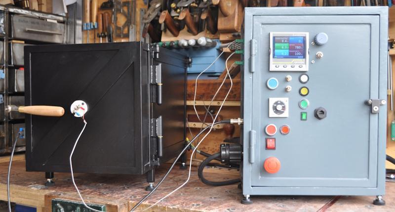
 by Dr.Al - This is my home-made heat treatment oven (for hardening and/or tempering of steel). I made it in two parts (a chamber and a control cabinet) for a couple of reasons. Firstly, it makes each individual part lighter so it's easier to move around (I don't have much space in my workshop so can't give the oven a permanent home). Secondly, it means I can use the control cabinet with other chambers (for example, at some point I'd like to "Pin It")
This is my home-made heat treatment oven (for hardening and/or tempering of steel). I made it in two parts (a chamber and a control cabinet) for a couple of reasons. Firstly, it makes each individual part lighter so it's easier to move around (I don't have much space in my workshop so can't give the oven a permanent home). Secondly, it means I can use the control cabinet with other chambers (for example, at some point I'd like to make a vertical cavity chamber for casting brass). The control gear is quite advanced (with the ability to do ramps, dwells and have multiple different programs pre-loaded into the controller) and hence it was preferable not to have to make another one for a second chamber.
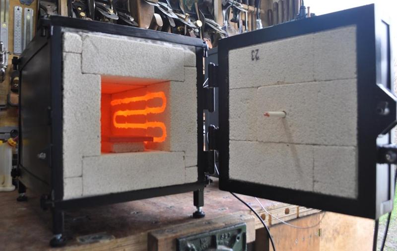
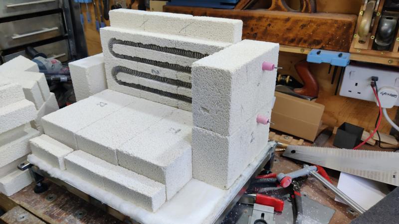
There are loads of details about the build on my website, including a 35-page build log that goes into exhaustive detail, but I'll share some specifics here as well. The materials used in the chamber core (insulating fire bricks and Kanthal A1 heating element wire) are rated to about 1250°C, although I'll only use it at temperatures quite a bit lower than that to give a bit of safety headroom. In practice I can't imagine I'll ever need to take it much above 1000 degrees; most heat treating is done at around 800.
It's designed to run off a 16 A single phase plug with the chamber itself taking about 12 A (about 2.8 kW); it heats up to 800 degrees in less than 20 minutes. The control cabinet has a current controller built into it, so I could in theory run it at a lower current (at the cost of a slower warm-up time) and then I could probably get away with using a standard 13 A three-pin plug.
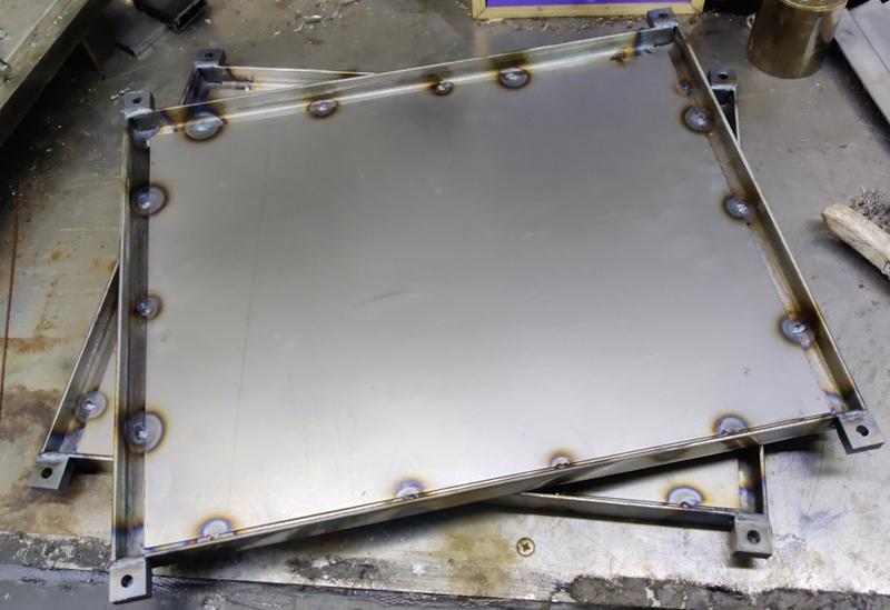
The chamber and the control cabinet are both made out of 20 × 20*× 3 mm angle iron, with sheet steel filling in the gaps. It probably would have been much more sensible to buy a box for the control cabinet and just cut the holes in it, but I enjoy TIG welding and it was an enjoyable exercise making it from scratch.
Unlike most of the heat treatment oven builds I've seen on youtube, I elected (based on advice from another forum) not to use any mortar or fire cement in the chamber. The bricks are held together by a combination of the friction between them and the steel frame holding them firmly in place. While this will slightly increase the heat loss from the oven, it has the significant advantage of making the oven serviceable. The main frame can be dismantled by undoing a few M8 screws and then any damaged bricks can be easily replaced.
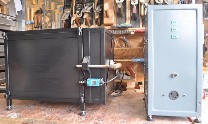
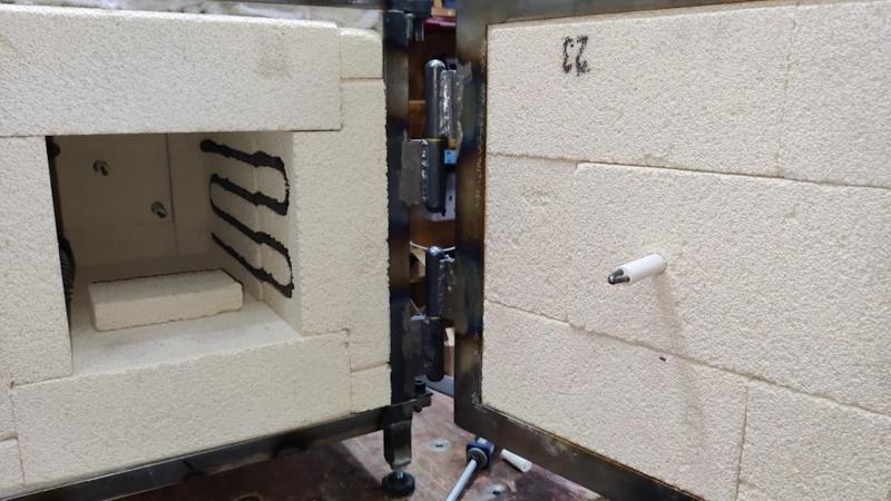
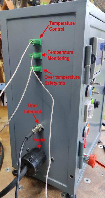
The chamber has three K-type thermocouples (two at the back and one in the door), which plug into the three standard green sockets on the side of the control cabinet. One of the thermocouples is used for temperature control, one for a safety over-temperature trip and the third provides a way of monitoring the temperature in a different part of the chamber. There's also a fourth thermocouple monitoring the temperature inside the control cabinet. The controller I'm using allows for multiple inputs and you can use one for the control loop and then wait for another to reach (a separately configurable) temperature before moving on to the next stage of the temperature cycle (for example using the thermocouple at the back of the chamber for the control loop and the one at the front as a stabilisation point to ensure even temperature).
The other connections from the chamber to the control cabinet are the power connector (also including a protective earth connection) and the one for the door interlock.
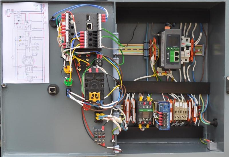
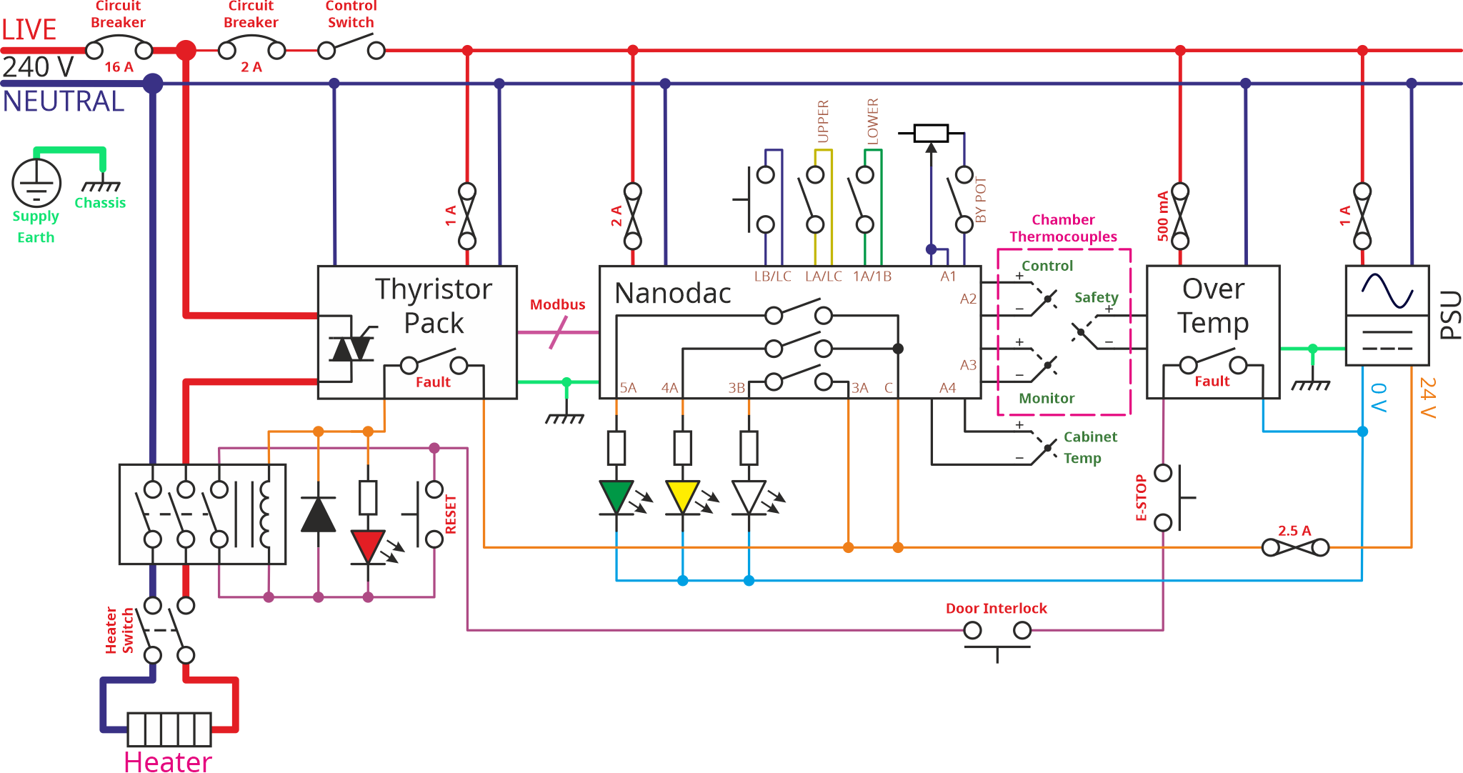
This photo shows the inside of the control cabinet. I was very fortunate to be given most of the modules in this box by a very generous member of the MIG-welding forum, so I was able to make it a lot more advanced than I would have been able to had I been buying all the bits myself. The "Nanodac" controller in particular is very capable, with the ability to program ramps and dwells for heat treating more exotic materials (although so far I've only used it for gauge plate and silver steel). Having never wired something like this up before, I spent a lot of time trying to make it neat and traceable, with almost every wire individually labelled at both ends using heat-shrink printable labels.
This image shows the schematic for the wiring of the control cabinet. It seems to be cropped in the forum preview view; click here to see it in full. There's a lot more detail explaining what each bit of the schematic does starting on page 7 of the build log on my website.
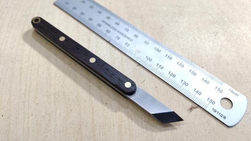
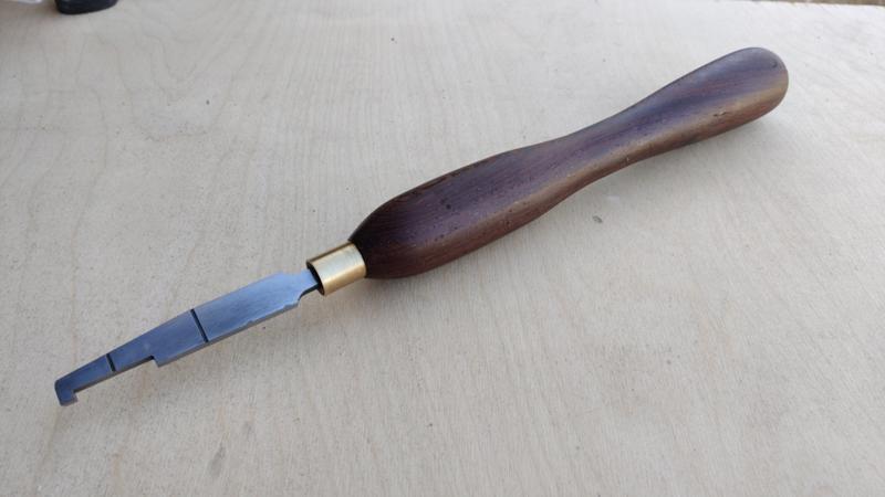
These images show the first couple of things that I made using the oven. There's a simple marking knife with Wenge scales and a woodturning tool for cutting the grooves for Crushgrind branded peppermill mechanisms (the handle for which was made on my home-made woodturning lathe). Both of these were made from gauge plate (ground flat O1 tool steel) and both are small enough that it would be relatively straightforward to heat treat them with a blow-torch, but they provided a nice way to try out the oven and prove that it worked properly.


 Reply With Quote


")


Bookmarks