 LinkBack URL
 About LinkBacks
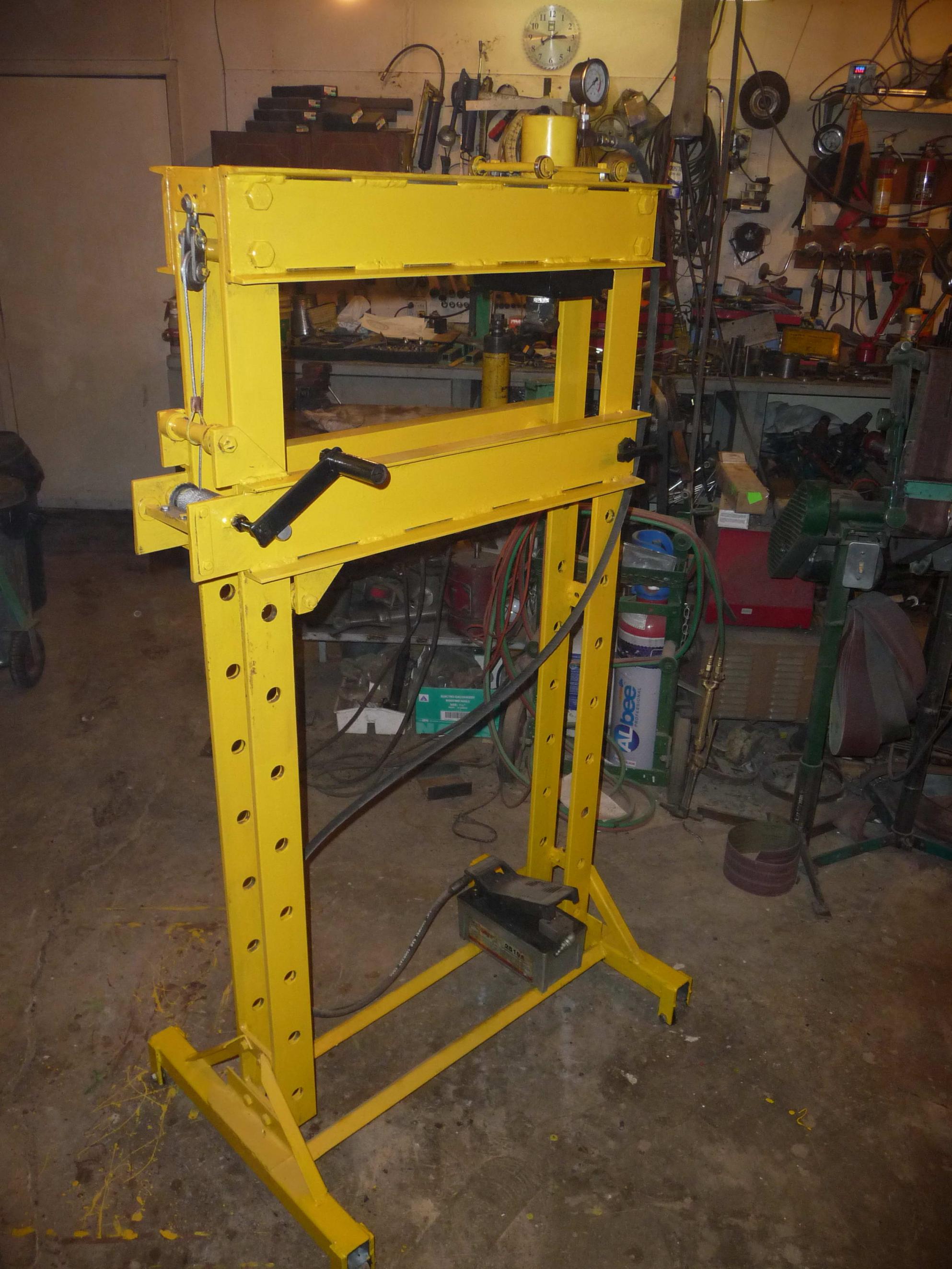
25 ton air over hydraulic
With guard and press break
Bed winch


25 ton air over hydraulic
With guard and press break
Bed winch
allenz (Nov 15, 2018), Andyt (Aug 28, 2020), clydeman (Aug 27, 2020), Jon (Feb 4, 2018), KustomsbyKent (Feb 4, 2018), LMMasterMariner (Apr 3, 2018), mtlman20 (Mar 16, 2026), Paul Jones (Apr 2, 2018), penca (Apr 1, 2018), PJs (Jul 28, 2018), Rangi (Aug 30, 2020), rossbotics (Feb 10, 2018), Seedtick (Feb 4, 2018), Toolmaker51 (Jul 28, 2018), tooly (Jul 26, 2018)


Bed winch is a nice touch.
New: BuildThreads.com - 300+ build posts/day (with photos)
hi glen
nice press man. what size are the uprights and pins? i`m rebooting my press for the nth time... thanks for sharing
regards. peter

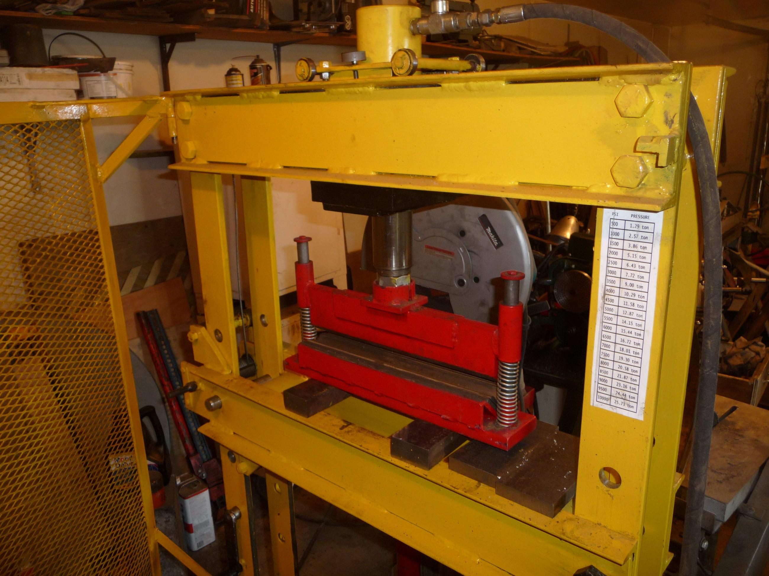
The uprights are 1/2" x 3" and the pins are 1" grade eight.
The bolts in the upper bridge are 3/4" grade eight.
The upper bridge for the cylinder carriage and bed are made from 1/4" x 5" channel and reinforced with 3/8" x 4" flat iron.
It is modeled after a 30 ton Enerpac press I used to use before I retired but is built a little heavier.
The commercial Enerpac used a small hydraulic hand pump for raising and lowering the bed which I didn't care much for but I did copy their vertical bed carriage design. It negates the need for stringing another cable around to the other side of the bed.
The winch handle is detachable as it would be in the road other wise. The winch also has a half moon shroud made of 14 or 16 gauge sheet metal to keep the cable in place and to keep it from "bird nesting", and works well.
clydeman (Aug 27, 2020), Paul Jones (Apr 2, 2018), penca (Apr 2, 2018), PJs (Jul 28, 2018)
thanks! lot of data to work on, i was on the light side for the uprights considering 3/8 by 3" but will go for the 1/2 as you did (and for the love of god i hope this time is the last time and i build the thing!). i was about to build my press the conventional way when i thought a four pillar would serve me better having the possibility to pass thru bars and stuff. and i`m still with the idea of using it as the frame for a tube roller (large radius) thanks a lot for the info. regards. peter
one thing i forgot watching in detail how the table is guided by the rollers is a nice nice idea, as i said i`m thinking of using the space btw uprights to straighten/bend things so cable and pulley would have to be mounted outboard but it`s a great idea
Last edited by penca; Apr 2, 2018 at 07:43 PM.

The winch cable would only be in the road when raising or lowering the bed. It can be pulled slack without the weight of the table and can be moved off to the side.
3/8" x 3" may very well be heavy enough for the uprights but being a millwright and not an engineer I tend to error on the side of caution.
penca (Apr 4, 2018)

I like your design, I may be missing something your lift cable must run through to the opposite side? I mounted my winch on the top beam but not as practical as yours, also I have to strengthen my top beams [up to 30Ton from 10Ton]so getting rid of the winch there would be great.Originally Posted by glens5

that's a real nice design, glen.
It's elegant simplicity, tooly.
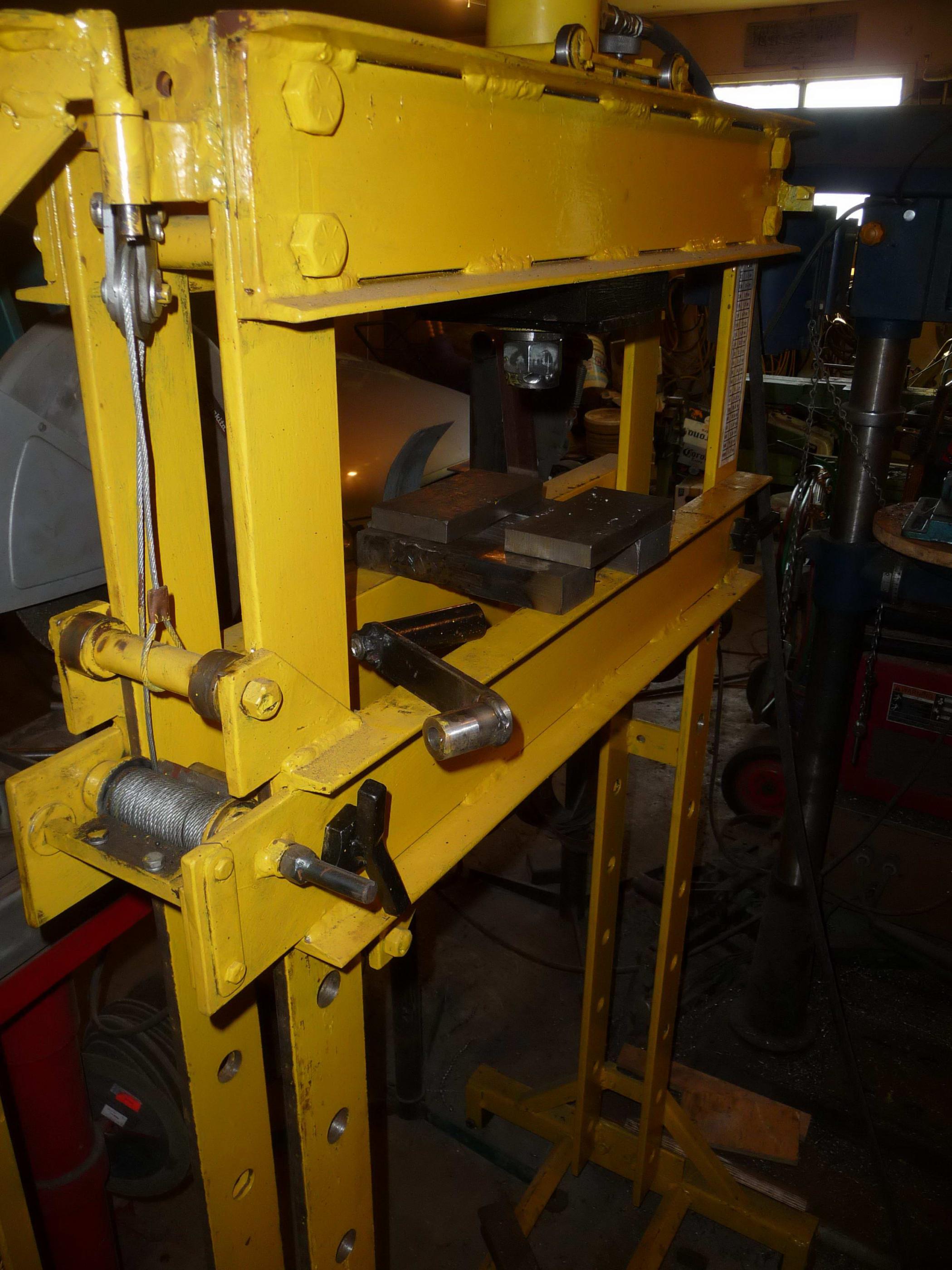
The left side of the bed has 2 sets of rollers.
One set is at the upper left, just above the cable "drum"
The 2nd set is on the right side of that same (left) upright.
Together they form a cantilever with the whole of the bed being supported by the left upright; the right end doesn't need a cable.
The it's just a matter of inserting the pins when the bed is raised/lowered to the desired height.

PJs (Jul 28, 2018)
There are currently 1 users browsing this thread. (0 members and 1 guests)
 Posting Permissions


 Reply With Quote

Bookmarks