
 LinkBack URL
 About LinkBacks

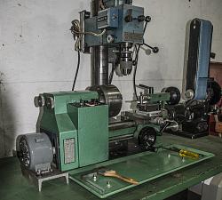
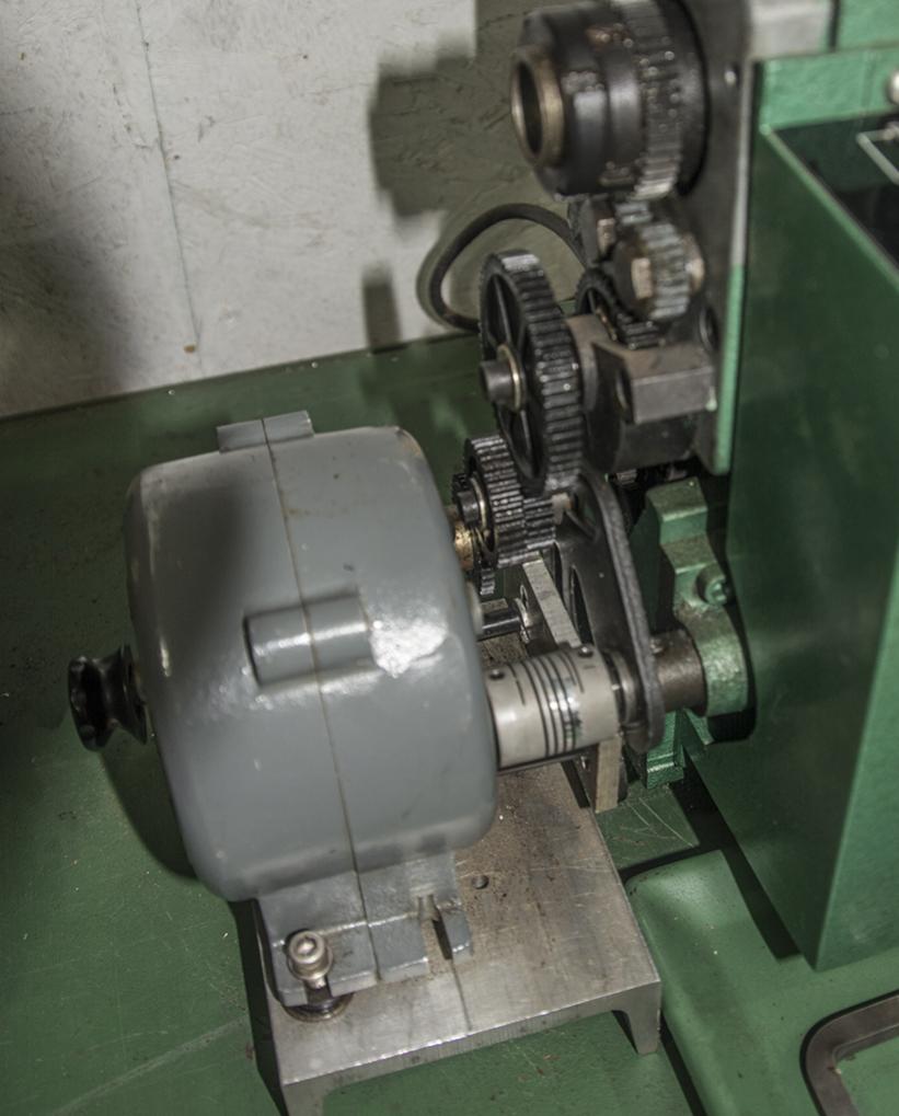
I have a Harbor Freight 7X10 mini lathe that was almost useless when I brought it home from the store. I think the designer had seen a lathe and knew what they were for but had never used one. There were many problems with the lathe but the basic structure was sound so I set about making improvements. My first mod was the gib that was on the back side of the saddle. That was made of cast iron and when adjusted it broke. Replaced that with a piece of bronze. The tailstock as supplied was not accurately adjustable for center. I added an adjustment screw and better clamping. The carriage cross slide travel was rather short so I extended the travel by an inch (see "Gordon Scott's Cross slide Mod", that's me!). The top slide was functional but very sloppy so I replaced it with a Cleveland slide. While the change gears available for the lathe are versatile they are not handy! I added a leadscrew gearbox that while not as versatile as change gears, permits a nice range of thread cutting and a superb selection of cutting speeds. It will cut 8,16,24,32 and 40 TPI and has an additional 5 speeds for cutting as slow as .002" per revolution of the spindle.


 Reply With Quote


, But I found a better solution. I will implement a mechanism to open the half nut when the carriage approaches the headstock. I have the method mostly worked out and will soon have it installed!
Thanks for your input!! "Pin It")


Bookmarks