
 LinkBack URL
 About LinkBacks


So brake's in my possession awhile, been 'tuning' and replacing the few missing items. Here I'll post a quick look at what took a little orchestration, and varied abilities.
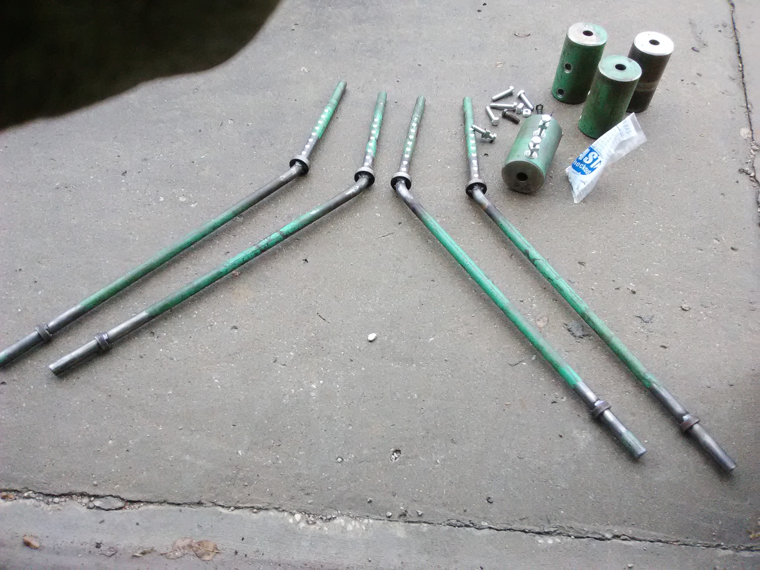
One counterweight was missing, simple part once scrap was found.
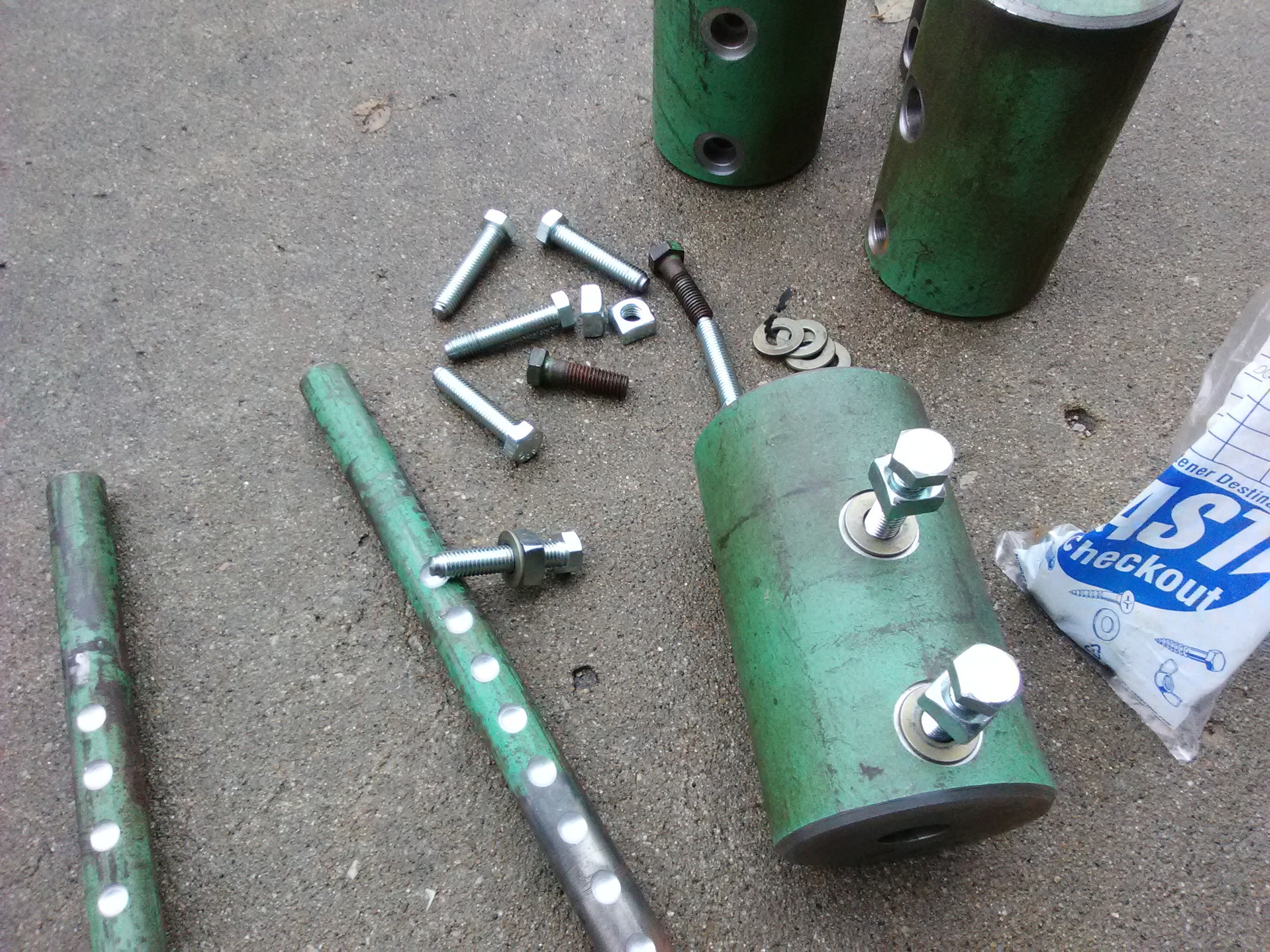
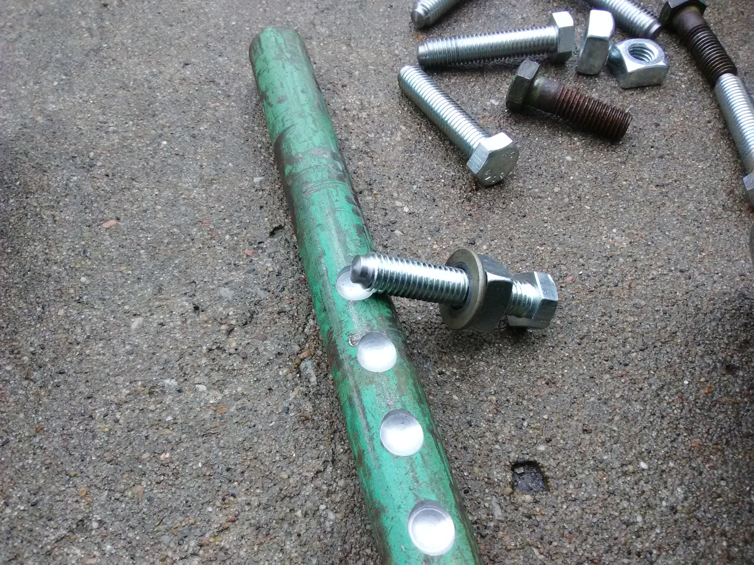
A machine axle cutoff yielded 4"Ø x 7", drilled through 1 1/64th Ø. Drilled and tapped 1/2"-13, 1.000" & 4" from end, same pattern added to other three weights. These are setscrew holes, bearing directly on the weight arm, designed poorly in original manufacture, knurled cup points marring the arm and impeding adjustment. A single weight is 25lbs, evidence shows being vertical might be 1 screw insufficient. Photos have solution, 2 dog-point screws, and shallow 3/8" radius detent, spaced 1.500 apart [half the three inch spacing of weights], about .200 deep. As weights connect to apron in tandem, no reason says they need precise identical setting of left and right side. That creates individual 1.500 increments, and should balance the apron fine.
While 4 arms came in purchase, one been modified with a awkward double bend, that reassembly didn't reveal cause. Of two pairs, easy to discern which 'sister' was correct. I hung both over edge of weld table, mounting spare weight on the one to fix. A acetylene rosebud did so quickly, monitoring it's descent into parallel with sample.
Now stop rings were welded in place. Originally, if weight slid down the arm, it'd jam at bend, very difficult to reposition. Used weight to locate ring closest to bend, and weld so weight and ring still faced each other squarely.
At same time, the other end, rings were welded in place to keep a dependable 'elevation'. Here again, 2 screws were taxed severely retaining an adjustment. I don't mind spending time to remedy shortcomings, especially related to saving hands or fingers.
Next, with all eight now paired alike, the detent pattern was milled into area weights connect to. They originate .020 farther from stop ring than the 1.000" of weights, to eliminate bind. The weight stop ring provides a dependable square surface to stop on, in this case mill vise edges.
Now, modifying new screws. Detents make this solution almost a finger-tight deal. Very simple turning dog-points on bolt ends, a little less than minor diameter of 1/2-13 thread. Locking is now external with square nut and washer, and a flat encircling the bolt hole. Bolts get anti-seize compound, just a 6" adjustable wrench will do the trick.
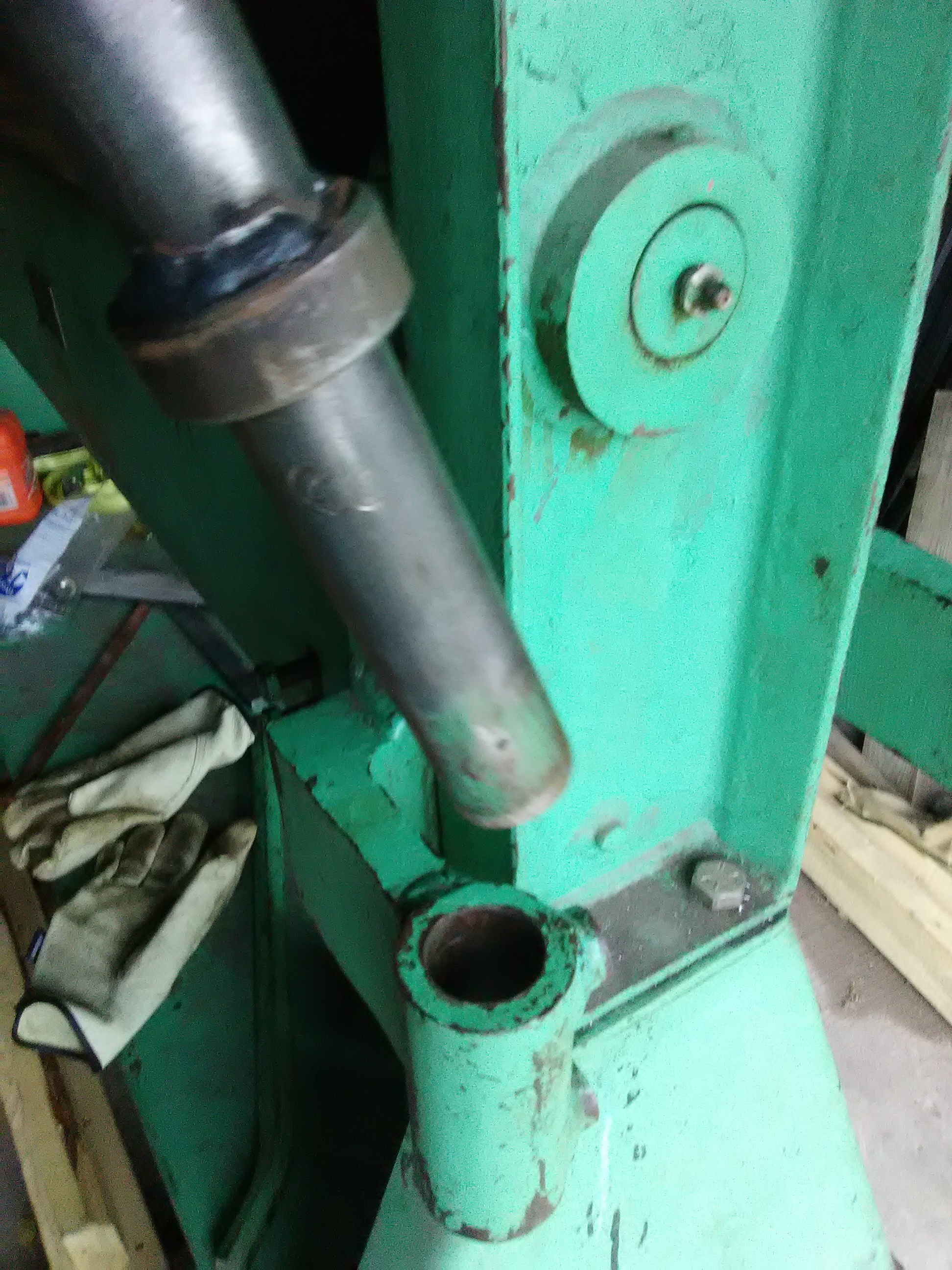
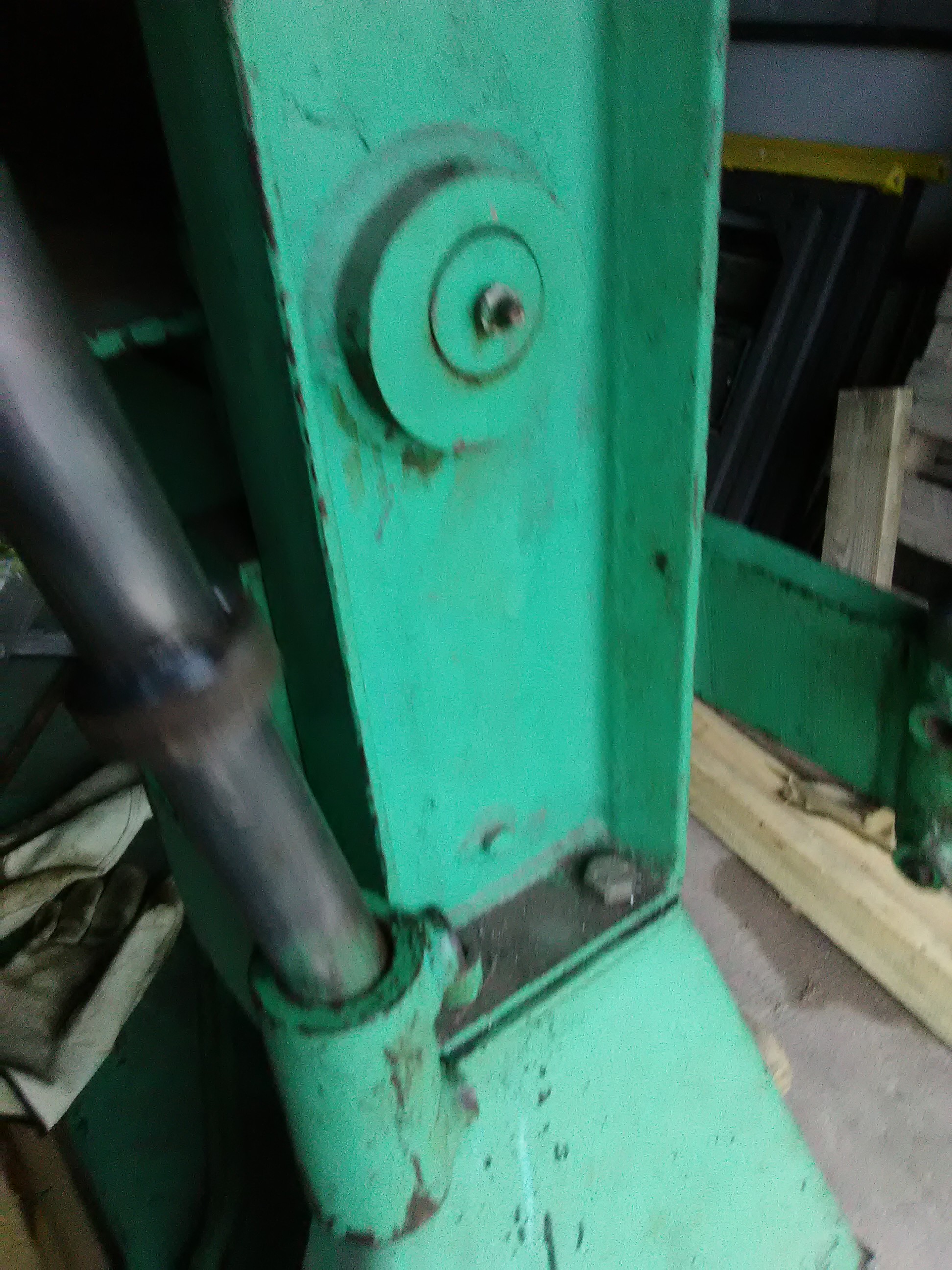
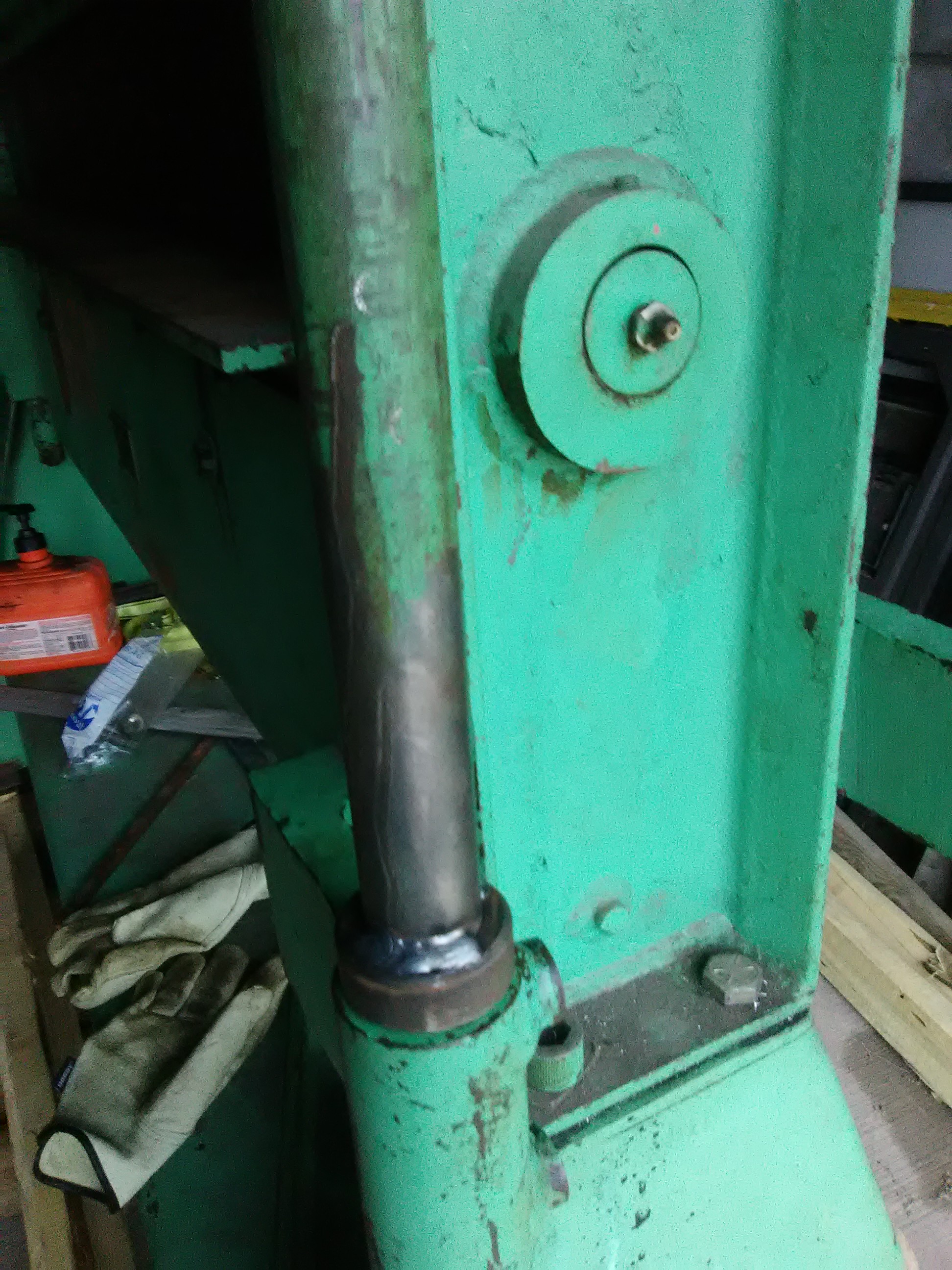
Way this brake works, is an apron either side of a descending die, not quite a press brake. Not sure why they wanted this arrangement, but it's growing on me. It can exceed 45° of a common brake. Everything [clamp and both aprons operate best from the 'main' side] and material stops [back gauge & front stop] can affix to either apron, and still have an extended table for deep parts.
Well, being equipped with all parts in hand shows why one had a custom bend....can also see their remedy was not very effective. I'll bend now at lower end to gain a couple inches deflection. Then balancing the aprons can proceed. Lower set screws will be used in socket, once correct splay of arms is determined. The back arms swing forward, so needing to miss the front arms. I'll spot drill detents, preserving their setting too.
Apron gauges are next. What I have as examples are cobbled uni-strut. Good idea, but misused and mangled. I can do better.


 Reply With Quote

Bookmarks