
 LinkBack URL
 About LinkBacks


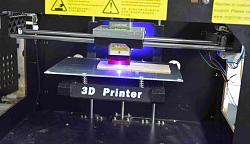
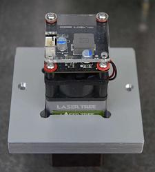
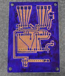
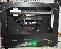
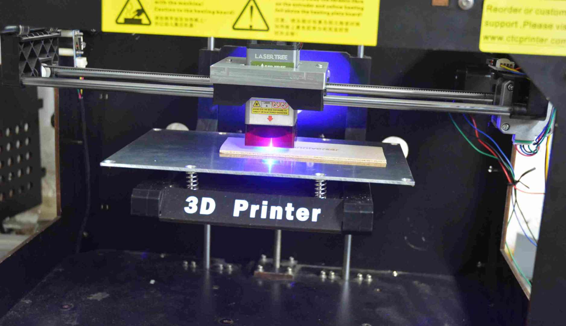
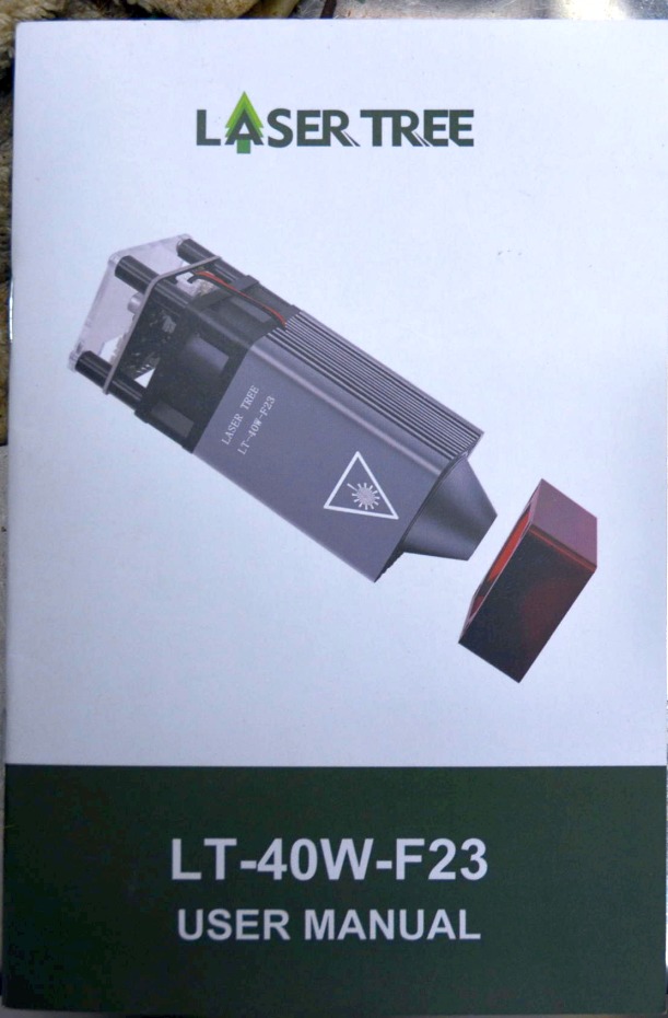
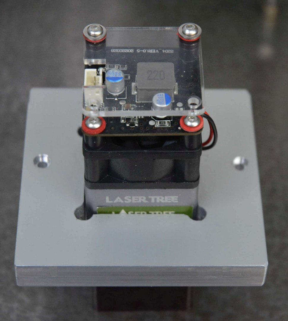
I became interested in learning if a laser engraver/cutter would have any use for me. My son had a surplus 3D printer and it seemed that it would be a simple and quick job to replace the 3D printing head with a laser module. I bought a low power laser diode variety as a low cost option to see if it might prove useful, if so then I could replace it with a more powerful laser at a later date. For reference the second photo shows the laser that I bought, it is specified as having an optical power of 5W +/- 1W. 10 and 20W are now common but the price increases considerably.
Click for full size pix.
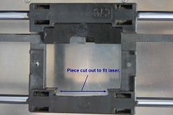
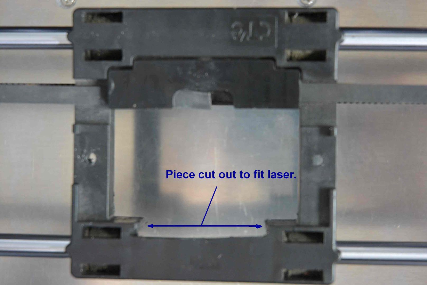
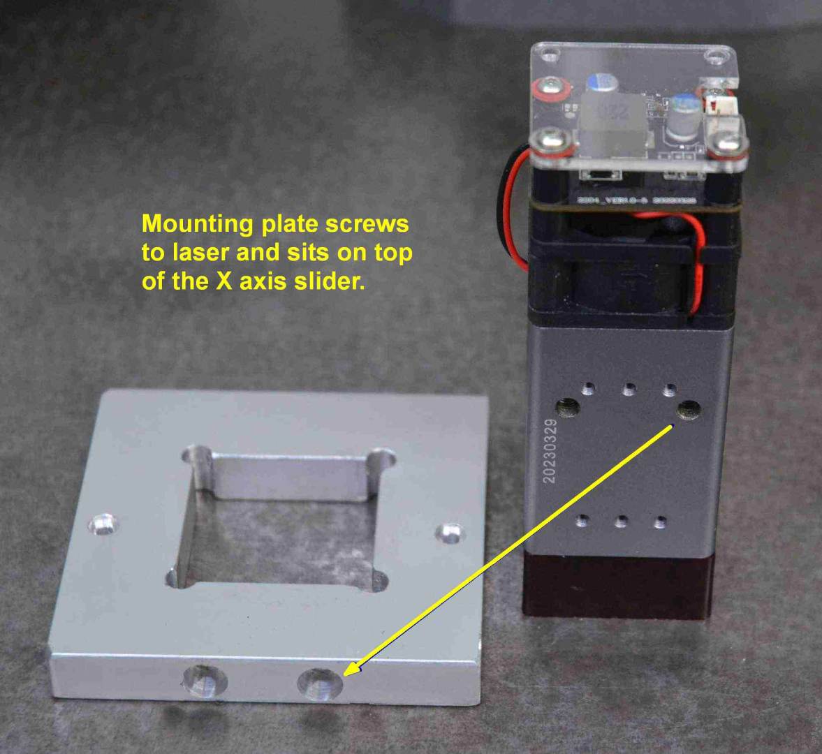
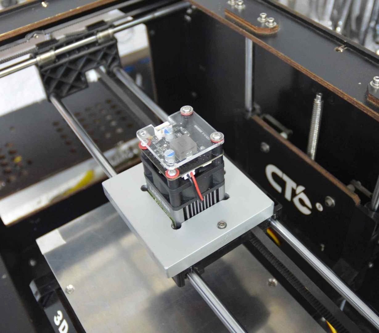
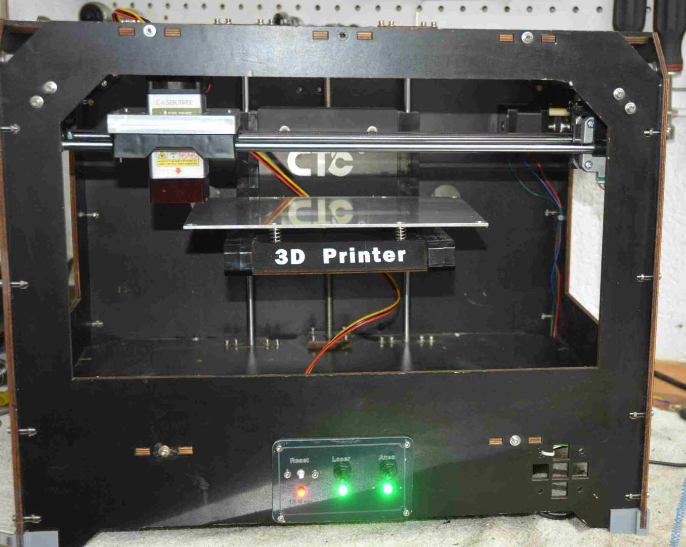
Once the print head was removed it left a horizontal surface to mount the laser head to but I had to cut a bit out for it to fit. Then I cut a square hole in a piece of aluminium plate to accept the laser and this plate sat on the original print head support. Hardly any work required.
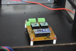
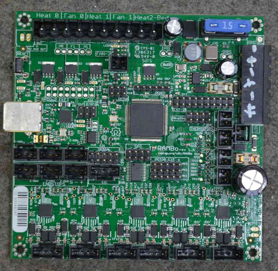
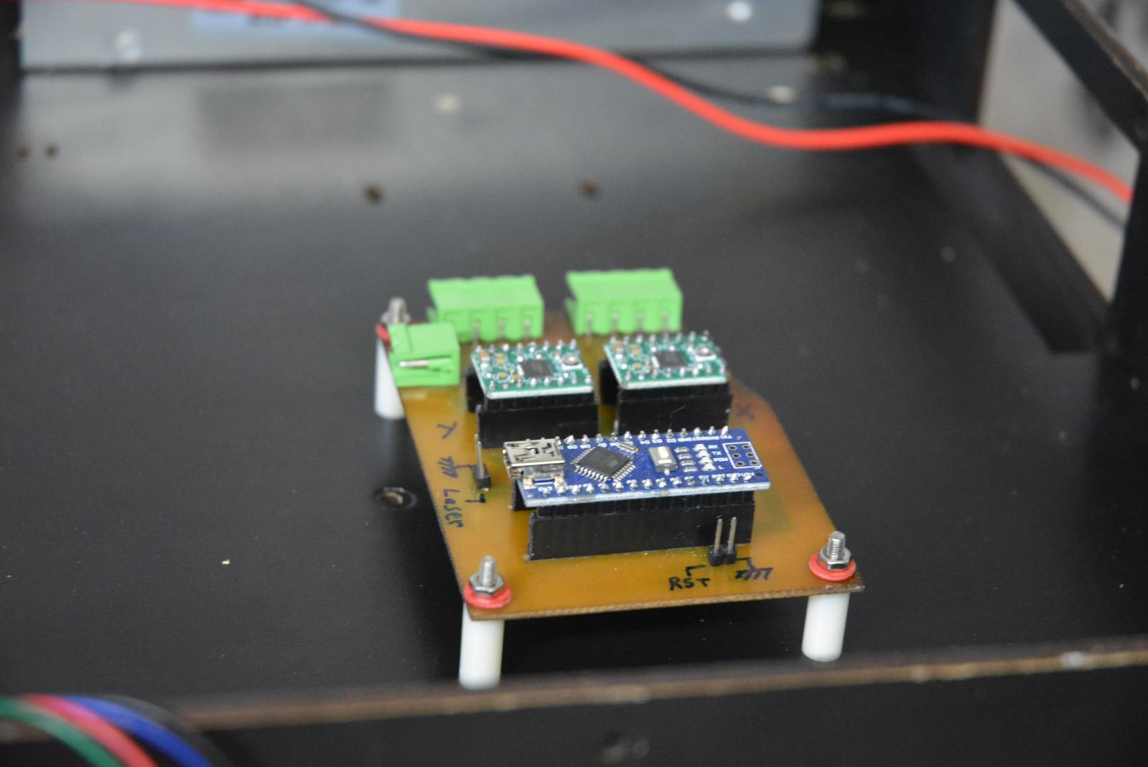
That pretty much took care of the mechanical modifications. That left the inevitable electronics and software to make the workpiece move. The 3D printer had small stepper motors and driver modules on the X & Y axis so I retained those. For simplicity I removed the drive for the Z axis and I do that manually to set the height of the laser. The printer had a control board to feed the motor drives but I decided that it would be quicker to make my own rather than figure out how to use the original and find matching software. The axes only need to move slowly on an engraver like this so I used an Arduino Nano as the brains and two of the original motor drives completed the electronic control. It was far simpler than the original board, and I do love simplicity.
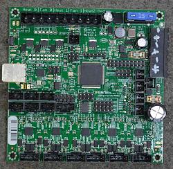
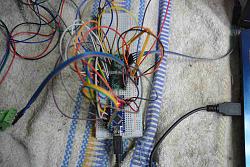
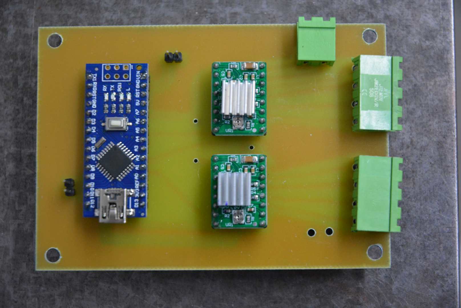
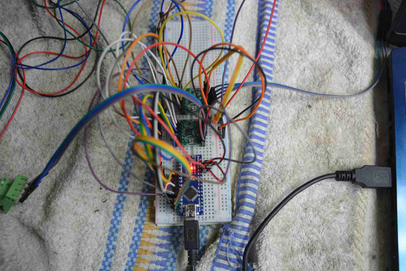
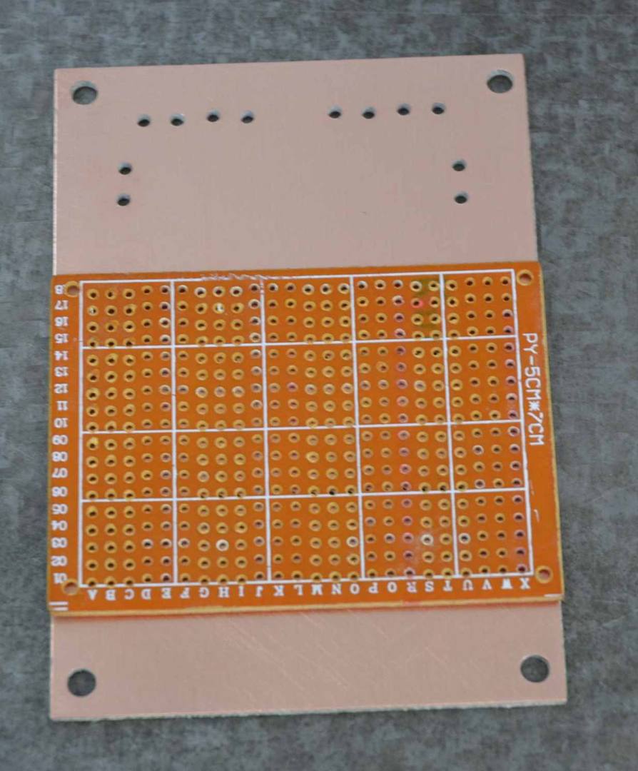
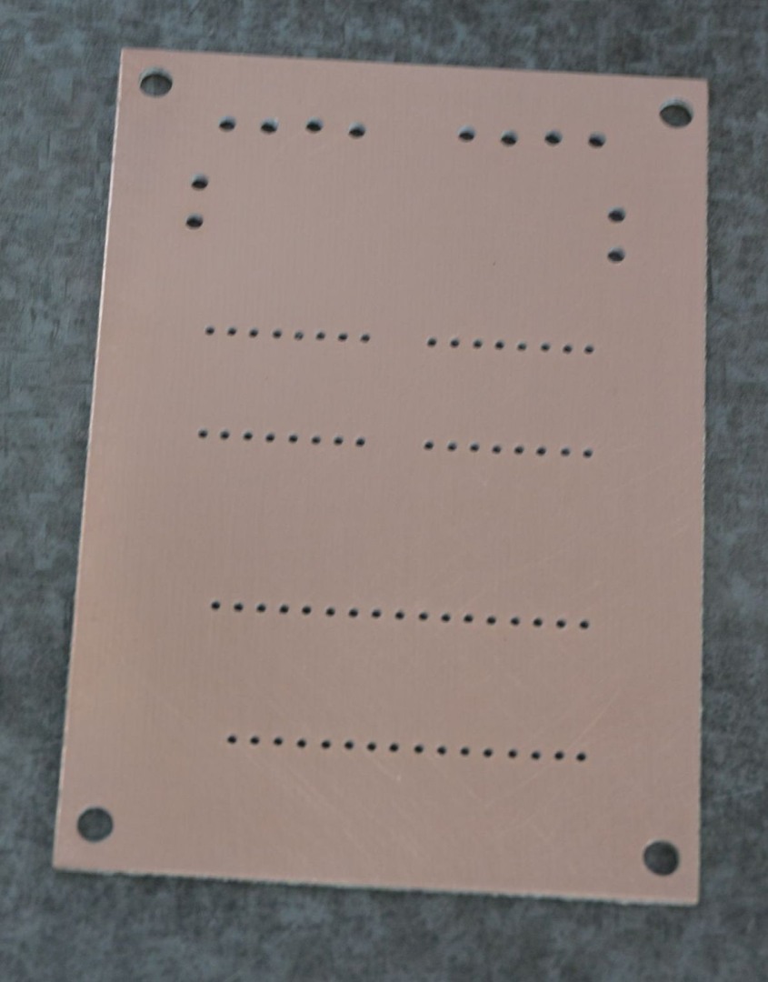
Rather than wire these together on vero board I decided to make a simple PCB to take the three modules plus some connectors. I managed to design a routing scheme with no tracks crossing so a single sided board was all that was necessary. Firstly I used a piece of Vero board as a template for drilling the pin holes at the required 0.1" spacing. I used a tiny handheld high speed drill for that (like a small version of a Dremel). The first photo shows the initial breadboard lash up for testing. It is always best to find any problems BEFORE making a PCB.

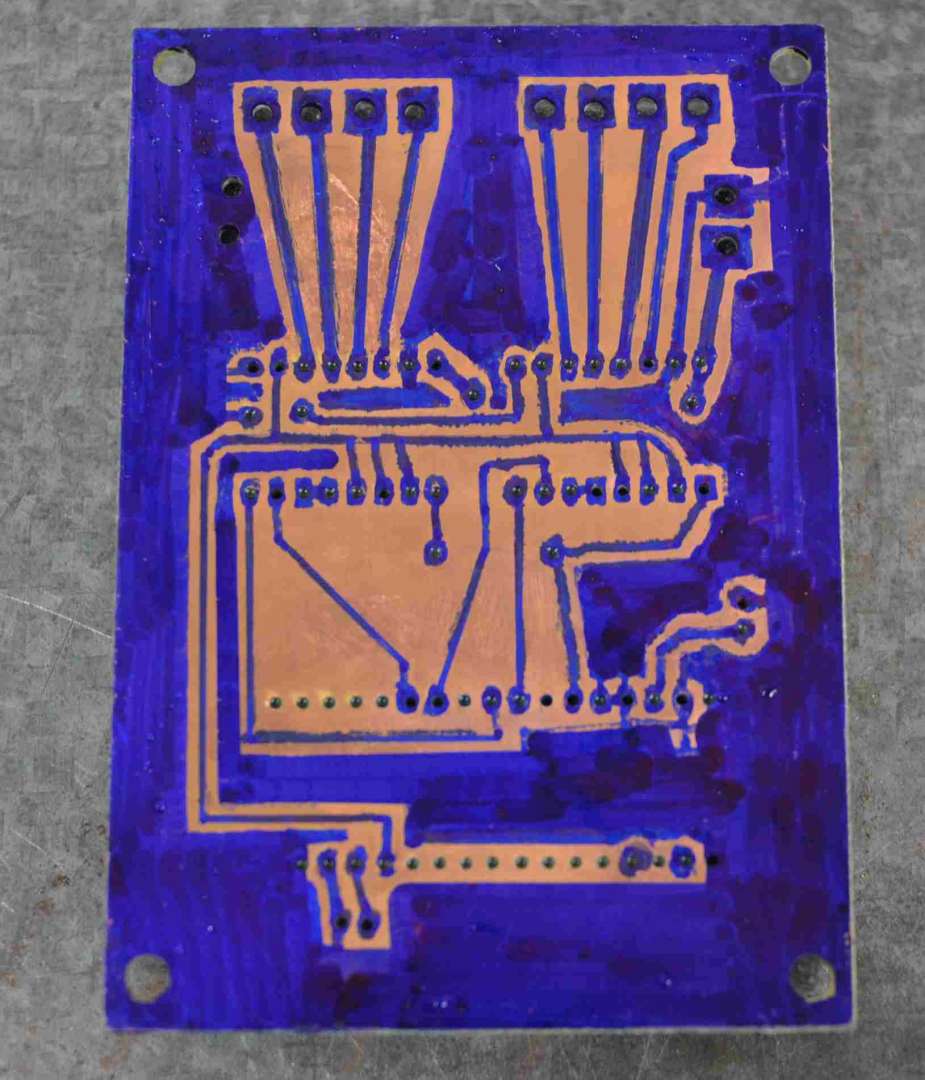
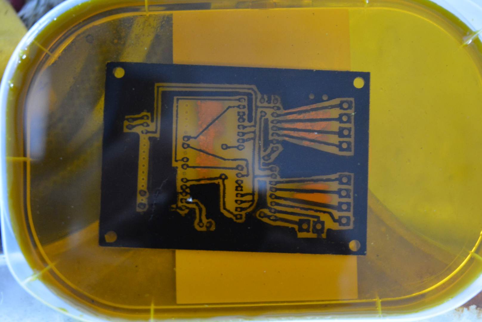
Using the holes as a guide I used an etch resist pen (a fine marker pen will do) to draw the circuit on the board and then a large marker pen to mask off most of the unused sections as an earth plane but which avoids depleting the etching solution more than necessary. Only the spaces between the traces will be etched away. Here is the board as drawn and being etched. Ferric cloride is the etchant. There are alternatives but I had that from years ago. The PCB is not up to professional standards but it works just as well, and this was just a quick conversion job not a life's work.
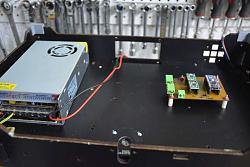
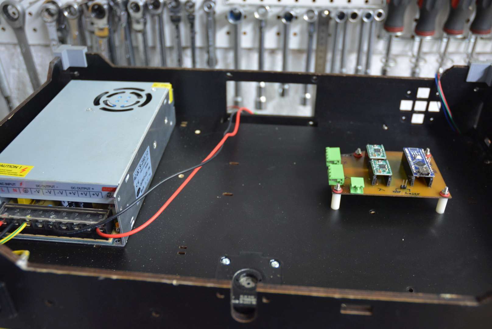
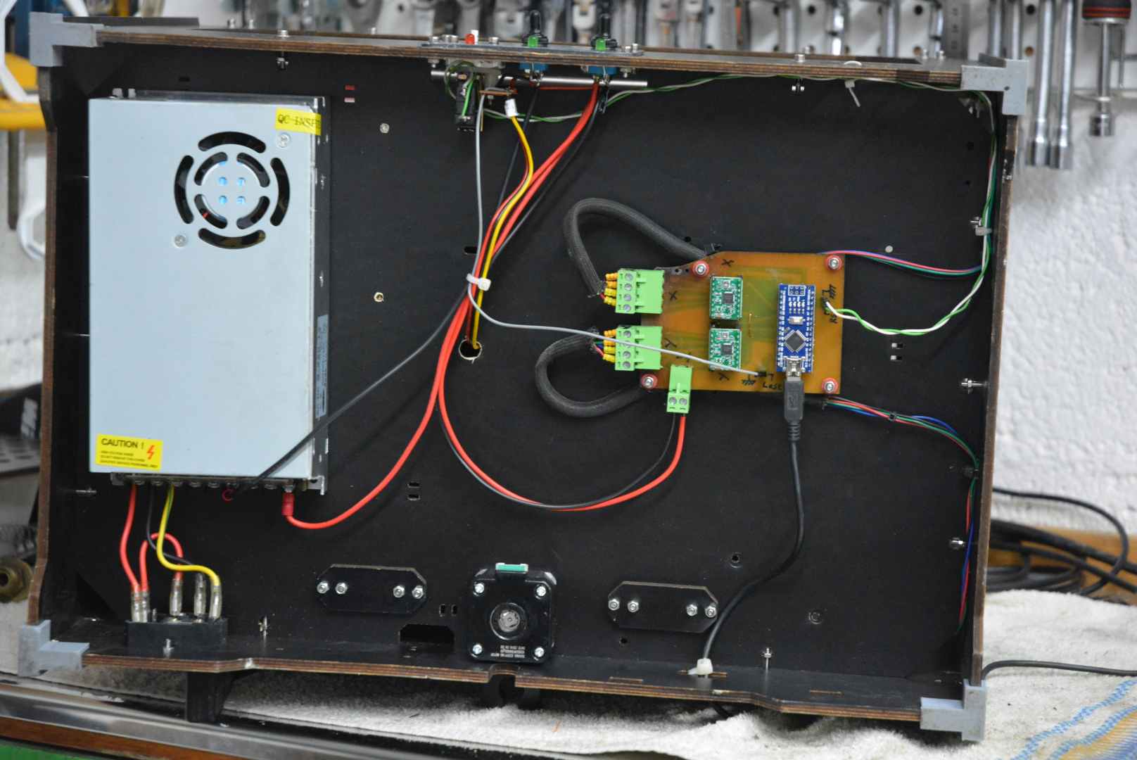
The 3D printer had a 12 volt DC power supply with a capacity way overkill for the laser but a 3D printer needs a heated bed, a heated extruder and filament feed as well as the axes movements and needs more power than the laser and its axes movements. It was there so I kept it and both the power supply and control/driver board were mounted in a space under the main body.
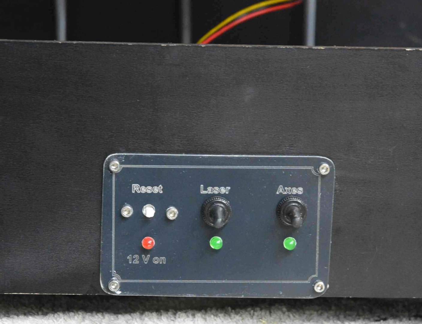
A simple switch panel completed the electrics. One switch each for the axes power and laser power, a reset button from an old PC serves as a reset for the Arduino. That has never been needed but it is done now. Three indicator LEDs complete the panel.
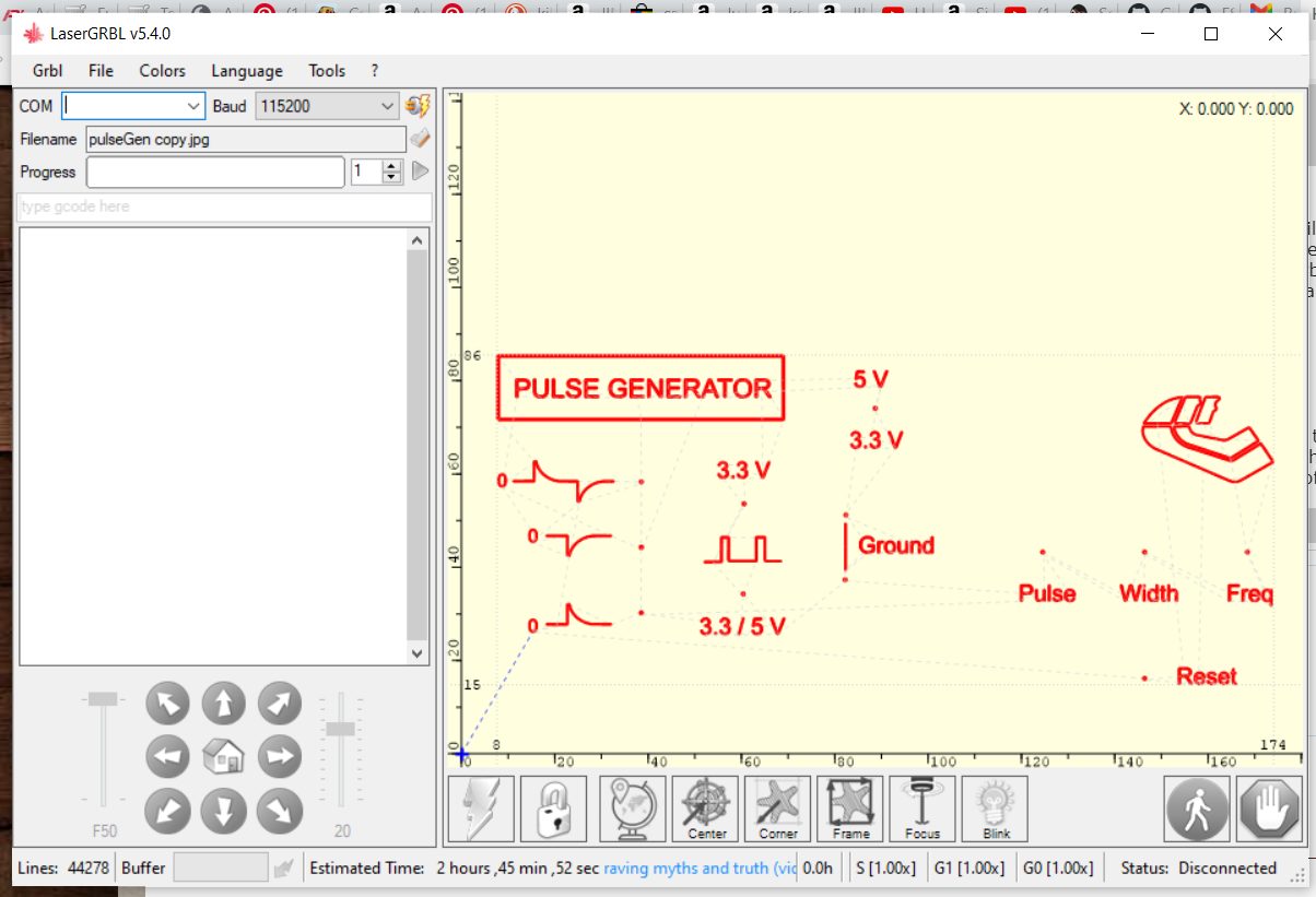
Just the software that is missing. This time I did not have to write my own. There is a well proven freeware programme written to turn base Arduinos into simple CNC controllers and that is the main reason why I chose the Arduino Nano. This is called GRBL and there is a ton of info on the net for those interested. GRBL is the software core of most of the dedicated budget CNC controllers from the east. There is a later more advanced version called GrblHAL which can work with a number of other more advanced micros but the extra speed and features are not necessary for an engraver like this. GRBL needs feeding with G-code and there is another freeware programme called LaserGRBL which takes files in a number of graphics formats and converts them into G code and sends to GRBL. this programme runs on a Windows PC attached to the Arduino and GRBL via a USB cable. The photo shows the LaserGRBL screen with the front panel of a pulse generator loaded ready to be engraved. The pulse generator is one that I built for testing ignition systems.
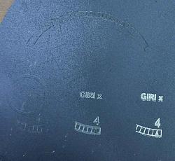
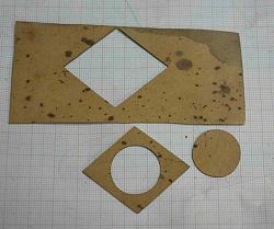
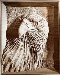
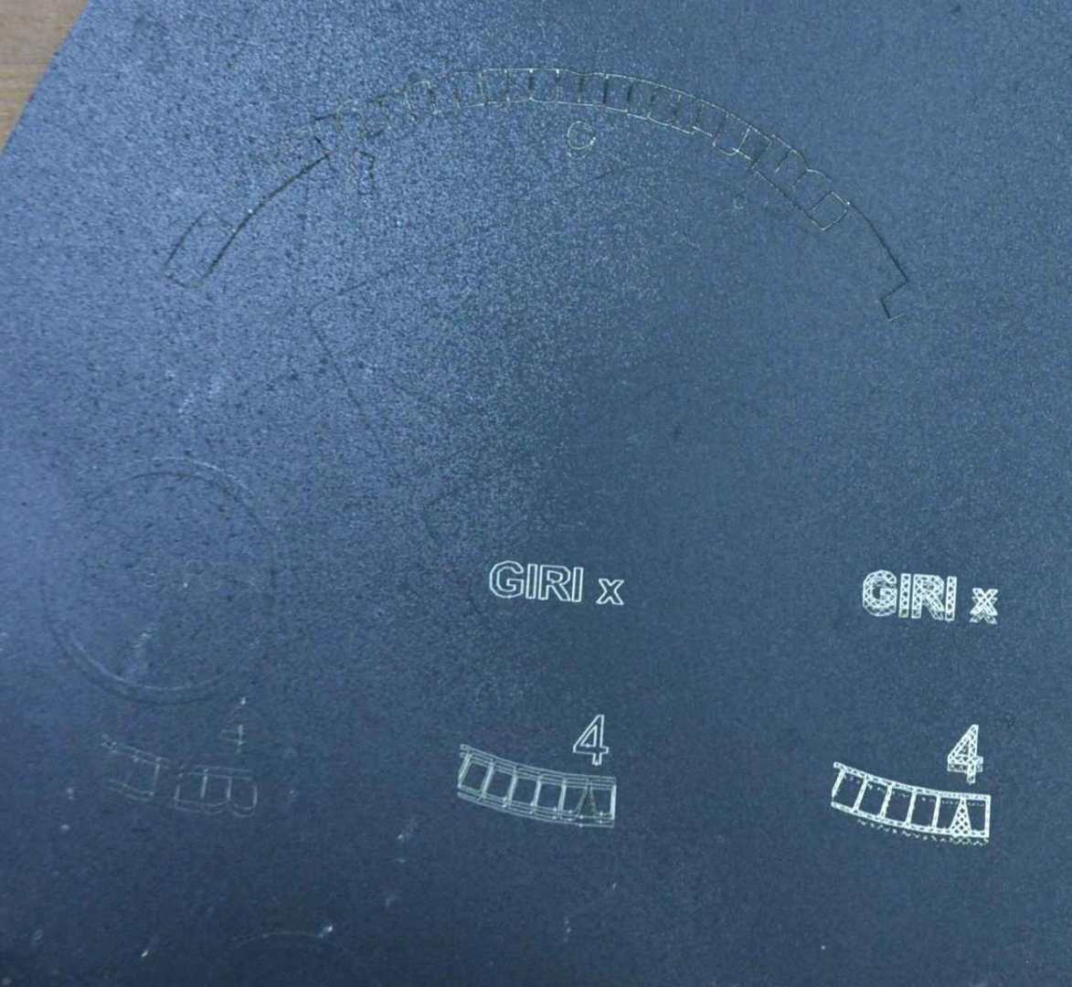
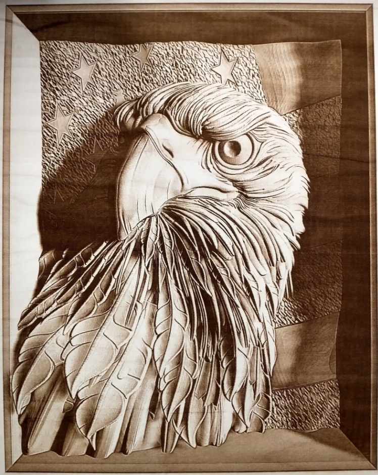
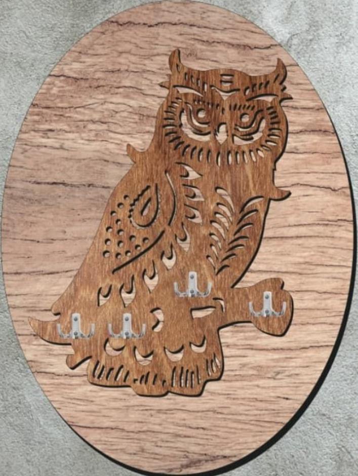
So what can it do? To be honest I have not done all that much with it and so I have only scratched the surface of the possibilities. Many people use units of this power for engraving artwork on wood but for serious workshop use it needs a laser of more power as I suspected in the beginning. The power that I have is fine for engraving panels with white lettering on a black background and it does a superb job of cutting out gaskets from thick gasket material. The gaskets come out with very clean cut edges. The first photo shows my first test, learning the software settings. The lower engraving and cutout photos are not my doing, they are from Pinterest.

PS. I have not shown a schematic because it is so simple and would depend on the motor drivers used, they do not all have the same pinouts. Do not ask me how I know. So you connect the four output wires of the stepper drivers to the stepper motors as per the spec sheet on the drivers and you connect the Arduino to the drivers as per the GRBL documentation, which also has full instructions for loading the software on the Arduino. It is a pretty simple and fun project.


 Reply With Quote

Bookmarks