
 LinkBack URL
 About LinkBacks


Hi All
To enable components to be machined with an inline boring bar on the lathe, a method of holding the job is needed.
During a skip dive of a local engineering company, I came across this steel ground plate which was either machined incorrectly or had done its job, so was disregarded and thrown out.
Straight away I had a plan for the plate (only hoping it wasn’t hardened and would be big enough for my big lathe to make a cross-slide jig plate.
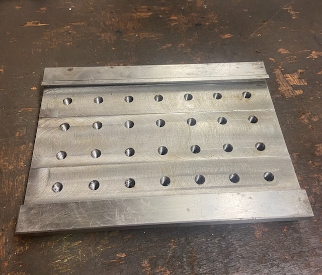
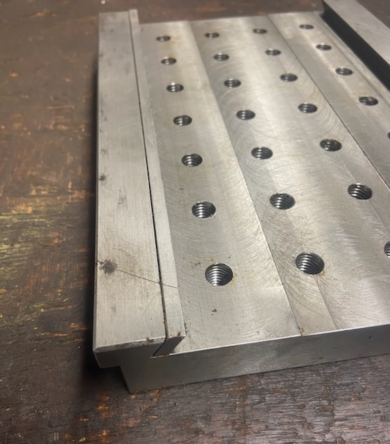
I couldn’t believe how lucky and how perfect this was going to be. Not only was the plate soft but was the perfect size and perfectly ground square. So the plate was marked out and the base of the plate machined with a dovetail and a jib strip to suit the dovetail of the cross slide.The jib strip is fitted, so when the grub screws are tightened to lock the plate in position the screws don’t damage the cross slide.
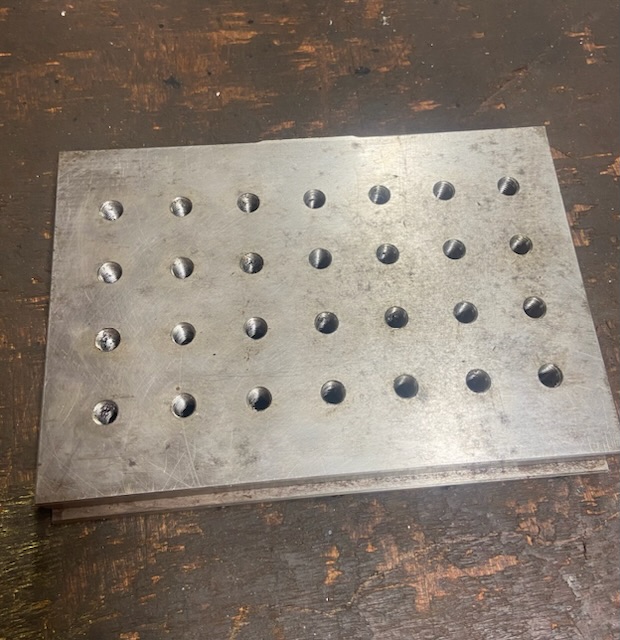
Next a series of M12 threaded holes were drilled so tooling/components can be clamped to it.
This was a really easy build due to the fact that a lot of the hard work had already be completed. Correct size plate and ground.
The photos below show the plate.
Top of jig plate.
Underside.
Jib strip located at each end with a dowel pins.
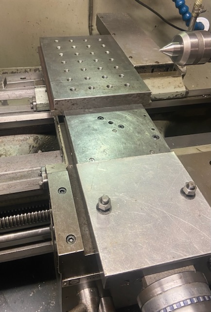
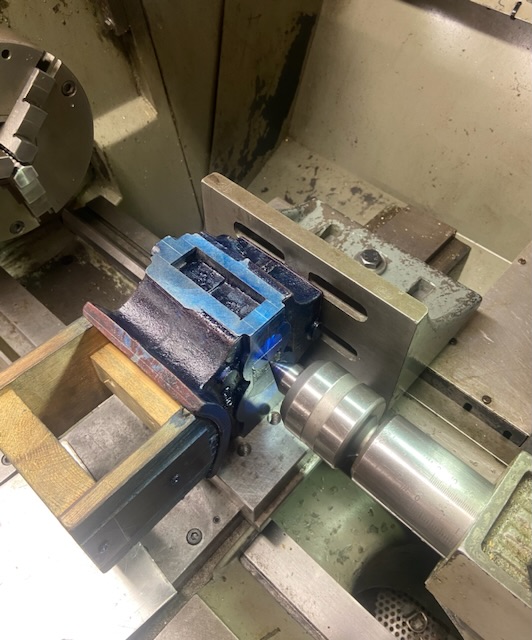
Jig plate in place. The compound slide is removed for better access and gives more space. The aluminium plate is bolted in place of the compound slide to prevent swarf from entering the tee slot and dowel hole.
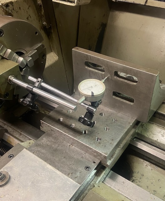
Angle plate clamped to jig plate and component held in place to check the position can be achieved on the cross-slide before clocking up and setting casting to correct height.
When happy with position the jig plate, grub screws can be locked in position and (in this case) the angle plate can be clocked square to the Z-axis.
Thank you for viewing. I will post a separate post on the alignment of the casting relevant to the casting centre line.
The Home Engineer


 Reply With Quote

Bookmarks