Free 186 More Best Homemade Tools eBook:  
Get 2,000+ tool plans, full site access, and more.

User Tag List

Page 1 of 2 1 2 LastLast
Results 1 to 10 of 17

Thread: Lever Action Clamping Screws

  1. #1
    Supporting Member Paul Jones's Avatar
    Join Date
    May 2014
    Location
    Del Mar, California
    Posts
    1,231
    Thanks
    5,810
    Thanked 1,440 Times in 655 Posts

    Paul Jones's Tools

    Lever Action Clamping Screws

    My 3” swing Unimat SL lathe, 7” swing mini lathe and 12” swing geared-head lathe all use various clamping and locking screws with M6-1 threads. I replaced the M6 cap head socket screws with my version of clamping screws and some with a swing-out levers to apply more torque. The swing-out levers eliminate using Allen wrenches.

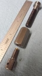
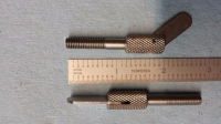
    The clamping screws were machined from 3/8” dia. 1018 CRS bar, the M6 threads cut with a tailstock mounted die, and the knurl is 21 pitch (whereby the 3/8” dia. was reduced to 0.364 before knurling). Some of the clamping screws have brass inserts at the screw tips to prevent marring the taper gibs on the lathe cross side and compound.

    The length of the clamping screws vary. The two screws for the mini-lathe change gear cover are 2.5” long. The Unimat headstock and milling head spindle slide clamping screws are 2” long and the drilling/milling conversion clamping screw is 1.1” (including brass tip). The 12” swing lathe compound locking screw is 1.1” (including brass tip) and the cross slide locking screw is 2.2” (including brass tip). The cross slide screw is longer than needed because it will be moved to the other side when this threaded hole is covered by the cross slide DRO sensor rail. All the parts were sprayed with Boeshield T-9 rust and corrosion prevention to keep the degreased surfaces from rusting.

    The swing out levers are 0.062” x 0.365” x 1.20” and hand finished with 3/16” end radii starting with 1/16” steel support rails salvaged from electronics rack panels. The slots in the clamping screw heads are 0.063” wide by 0.450” deep. The levers are retained with 3/32” roll pins shortened to fit. Finding the 1/16” thick steel was the hardest part of this project because most CRS bar stock are 1/8” or thicker.
    Attached Thumbnails Attached Thumbnails Lever Action Clamping Screws-assortment-clamping-screws-lathes.jpg   Lever Action Clamping Screws-compound-locking-clamp-12-inch-swing-geared-head-lathe.jpg   Lever Action Clamping Screws-unimat-m6-1-spindle-clamp-screws.jpg   Lever Action Clamping Screws-unimat-spindle-clamping-screws-installed.jpg   Lever Action Clamping Screws-cross-slide-locking-clamp-12-inch-swing-geared-head-lathe.jpg  

    Lever Action Clamping Screws-clamping-screws-mini-lathe-change-gear-cover.jpg   Lever Action Clamping Screws-using-vise-press-roll-pin-clamping-screw.jpg   Lever Action Clamping Screws-setting-radii-levers-clamping-screws.jpg   Lever Action Clamping Screws-cutting-0.063-inch-slot-clamp-screw-head.jpg   Lever Action Clamping Screws-salvaging-one-sixteenth-thick-steel-clamp-screw-levers.jpg  


    186 More Best Homemade Tools eBook
    Last edited by Paul Jones; Nov 2, 2015 at 08:35 AM.

  2. The Following 14 Users Say Thank You to Paul Jones For This Useful Post:

    aphilipmarcou (Nov 10, 2017), ATK 11 (Nov 1, 2015), Big-Pete (Dec 20, 2019), Captainleeward (Nov 5, 2015), Christophe Mineau (Nov 3, 2015), jjr2001 (Sep 1, 2016), Jon (Nov 1, 2015), kbalch (Nov 2, 2015), lazarus (Jul 13, 2016), MetalDesigner (Nov 26, 2015), Metallurg33 (Jan 22, 2024), NortonDommi (Nov 9, 2017), PJs (Nov 2, 2015), rlm98253 (Nov 8, 2017)

  3. #2
    Supporting Member Catfish's Avatar
    Join Date
    Oct 2013
    Location
    Mariposa, California
    Posts
    268
    Thanks
    55
    Thanked 414 Times in 156 Posts

    Catfish's Tools
    Very nice Paul. The knurls are clean.

    2000 Tool Plans

  4. The Following 2 Users Say Thank You to Catfish For This Useful Post:

    Captainleeward (Nov 5, 2015), Paul Jones (Nov 2, 2015)

  5. #3
    Content Editor
    Supporting Member
    DIYer's Avatar
    Join Date
    Aug 2013
    Posts
    3,056
    Thanks
    772
    Thanked 1,850 Times in 1,652 Posts
    Beautiful work, and nice detail on those pictures too.

  6. The Following 2 Users Say Thank You to DIYer For This Useful Post:

    Captainleeward (Nov 5, 2015), Paul Jones (Nov 2, 2015)

  7. #4
    Supporting Member Paul Jones's Avatar
    Join Date
    May 2014
    Location
    Del Mar, California
    Posts
    1,231
    Thanks
    5,810
    Thanked 1,440 Times in 655 Posts

    Paul Jones's Tools
    Thank you, Randy and DIYer,

    These were easy to make and even easier to use. I made a fixture for holding the knurled screw head for the slot cutting work. There is a M8 cap screw for locking in place the shorter M6 clamping screws and a hex nut for locking in place the longer versions. Here are some photos.

    Regards, Paul
    Attached Thumbnails Attached Thumbnails Lever Action Clamping Screws-fixture-holding-clamp-screw-drilling-slotting.jpg   Lever Action Clamping Screws-fixture-parts-holding-clamping-screw-slotting.jpg   Lever Action Clamping Screws-fixture-holding-clamping-screw-when-drilling-slotting.jpg   Lever Action Clamping Screws-cutting-slot-into-clamping-screw-head.jpg   Lever Action Clamping Screws-screw-slotting-cross-drilling-fixture.jpg  

    Lever Action Clamping Screws-unimat-drilling-roll-pin-hole-clamping-screw-head.jpg  
    Last edited by Paul Jones; Nov 7, 2015 at 07:15 AM.

  8. The Following 6 Users Say Thank You to Paul Jones For This Useful Post:

    Captainleeward (Nov 5, 2015), Christophe Mineau (Nov 3, 2015), Jon (Dec 5, 2019), nevadablue (Nov 3, 2015), PJs (Nov 3, 2015), robah (Nov 3, 2015)

  9. #5
    Content Editor
    Supporting Member
    DIYer's Avatar
    Join Date
    Aug 2013
    Posts
    3,056
    Thanks
    772
    Thanked 1,850 Times in 1,652 Posts
    Thanks Paul! We've added your Lever Action Clamping Screws to our Lathe Accessories category, as well as to your builder page: Paul Jones' Homemade Tools. Your receipt:


  10. The Following 2 Users Say Thank You to DIYer For This Useful Post:

    Captainleeward (Nov 5, 2015), Paul Jones (Nov 3, 2015)

  11. #6
    Content Editor
    Supporting Member
    DIYer's Avatar
    Join Date
    Aug 2013
    Posts
    3,056
    Thanks
    772
    Thanked 1,850 Times in 1,652 Posts
    Thanks Paul! We've added your Screw Slotting Fixture to our Miscellaneous category, as well as to your builder page: Paul Jones' Homemade Tools. Your receipt:


  12. The Following 2 Users Say Thank You to DIYer For This Useful Post:

    Captainleeward (Nov 5, 2015), Paul Jones (Nov 3, 2015)

  13. #7
    Supporting Member Christophe Mineau's Avatar
    Join Date
    Jul 2014
    Location
    France, Brittany !
    Posts
    913
    Thanks
    825
    Thanked 1,687 Times in 481 Posts

    Christophe Mineau's Tools
    Hi Paul, very nice job !
    I see you are using your lever screws on the sides of the dovetails of your slides. I suppose it is for pressing the wedges that serve to reduce the play in the dovetail ?
    This is something that I have a lot of difficulty to setup on my Chinese lathe.
    You seem to have one single screw for that where I have several little set screws (so tiny head that they will end up to be worn sooner or later), and they are locked using a slim nut.

    I feel my slides are whether too loose, and I have vibrations or even worse, I sometime see the tip of my cutting tool rolling under the piece .... Or I have them too tight, so with no play, but the cranks become difficult to turn ...

    Could you provide an advice on how to setup properly these screws ? Maybe I should replace them right now by scews with heads or knurled buttons like you.

    I don't see any locking nut on your screws ? no need for that ?

    Thanks in advance !
    Christophe
    Cheers !
    Christophe
    ________________________________________________________________
    Visit my Website : http://www.labellenote.fr/
    Facebook : La Belle Note
    All my personal works, unless explicitly specified, are released under
    Creative Commons BY-NC-SA license.

  14. The Following User Says Thank You to Christophe Mineau For This Useful Post:

    PJs (Nov 3, 2015)

  15. #8
    Supporting Member Paul Jones's Avatar
    Join Date
    May 2014
    Location
    Del Mar, California
    Posts
    1,231
    Thanks
    5,810
    Thanked 1,440 Times in 655 Posts

    Paul Jones's Tools
    Christophe,

    The compound and cross slide on my 12" swing lathe use tapered gibs. The gib is wedge-shaped and adjusted by loosening or tightening an adjustment screw located on the end of the gib and not on the side. The lever action locking screws gently push on the side of the tapered gib and add some sliding resistance. It takes just a fraction of a turn to lock the tapered gibs. I keep the compound locked down in normal operation and the cross slide is almost never locked. The tapered gibs are very easy to adjust and are an excellent design feature but more expensive to manufacture.

    I think the gibs on your lathe are similar to what I have on my 7" swing mini lathe. I bought my mini lathe in 1993 and this one was made in Taiwan but looks just like the Chinese designs. The mini has three set screws along the edges of the compound and cross slide for adjusting a flat gib (not tapered) with a rhomboid cross section. I honed these gibs to be very smooth and flat, and enlarged the shallow dimples where the side adjusting set screws rest. It took a lot of work but the mini lathe compound and cross slide run very smoothly. There is a fourth screw used as the locking screws and I plan to replace these smaller diameter metric hex head cap screws with my lever action locking screw. It will probably be an M5 and not M6. I provided a photo for clarity and will post the changes at a later date.

    I hope this helps with your question.

    Thank you for asking, Paul
    Attached Thumbnails Attached Thumbnails Lever Action Clamping Screws-mini-lathe-view-compound-factory-gib-adjustment-locking-screw.jpg   Lever Action Clamping Screws-mini-lathe-side-view-factory-gib-adjustment-locking-screw.jpg  
    Last edited by Paul Jones; Nov 3, 2015 at 10:47 AM.

  16. The Following User Says Thank You to Paul Jones For This Useful Post:

    PJs (Nov 3, 2015)

  17. #9
    PJs
    PJs is offline
    Supporting Member PJs's Avatar
    Join Date
    Sep 2014
    Location
    Northern CA
    Posts
    1,841
    Thanks
    8,333
    Thanked 1,118 Times in 718 Posts

    PJs's Tools
    Thanks Paul for the great write up and pics. Looks like you went into production there! Pretty handy and good ideas for all the uses. Knurling is real clean and looks like you might have used my knurl calc based on the number I saw. I do those brass tips sometimes too and curious of your method of inserting them...thread or sliding/press fit with LT603? For mine I have a bit of a rule of thumb...the smaller screws I tend toward press in, larger screws - thread them, but not hard and fast based on the application. Nice fit and finish to yours! Also a Big Fan of Boeshield products! Great Mods! ~PJ
    ‘‘Always do right. This will gratify some people and astonish the rest.’’
    Mark Twain

  18. #10
    PJs
    PJs is offline
    Supporting Member PJs's Avatar
    Join Date
    Sep 2014
    Location
    Northern CA
    Posts
    1,841
    Thanks
    8,333
    Thanked 1,118 Times in 718 Posts

    PJs's Tools
    Hi Christophe. Thought I might chime in here as well, as I think we have similar issues and peanut Sieg's. It has always been a constant vigil to keep the all the gibs adjusted properly for me. I personally started out with the LMS procedure. It's kind of an art and feel but you get faster after about 20 times.

    The "Roll Under" you speak of is likely caused by the Carriage retainer slides. You can also use the LMS procedure for that, but I added a bit of blue Locktite (242) to each of the screws prior to adjustment. It has helped tremendously on the frequency of adjustment. Also by sliding the carriage the full length of the ways while adjusting. My old bed is worn more toward the chuck so I adjust them so the are snug there and will barely pull off the end of the ways.

    There are lots of reasons for the constant vigil but primarily it's the Gib material (beer cans), IMHO. I will be making a custom set from Silicon Bronze for my new bed and extended cross slide. It's harder, provides good lubricity and won't tend to distort so easily from repeated adjustments...although I'm hoping to minimize that too with all my hand work to get them square, parallel and perpendicular with better tolerances over all. Again the material on a $500 lathe is not so good so it won't solve every thing. I have seen some YT DIY Turcite applications which might eliminate some of that...but it's still a $500 lathe with $5k in labor. ~¿@

    Hope this helps! ~PJ
    ‘‘Always do right. This will gratify some people and astonish the rest.’’
    Mark Twain

Thread Information

Users Browsing this Thread

There are currently 1 users browsing this thread. (0 members and 1 guests)

Tags for this Thread

Bookmarks

Posting Permissions

  • You may not post new threads
  • You may not post replies
  • You may not post attachments
  • You may not edit your posts
  •