Free 186 More Best Homemade Tools eBook:  
Get 2,000+ tool plans, full site access, and more.

User Tag List

Page 2 of 3 FirstFirst 1 2 3 LastLast
Results 11 to 20 of 29

Thread: Motorized rotary table

  1. #11
    Supporting Member tonyfoale's Avatar
    Join Date
    Nov 2016
    Location
    Spain
    Posts
    1,566
    Thanks
    690
    Thanked 2,646 Times in 709 Posts

    tonyfoale's Tools
    I have put the code for the control on dropbox, here is the link https://www.dropbox.com/s/2021uz1x4s...Rotab.ino?dl=0

    To load it into the Arduino IDE you will need to put it in a directory called Rotab (It must be exactly the same as the .ino file name.) That is an Arduino rule not mine.
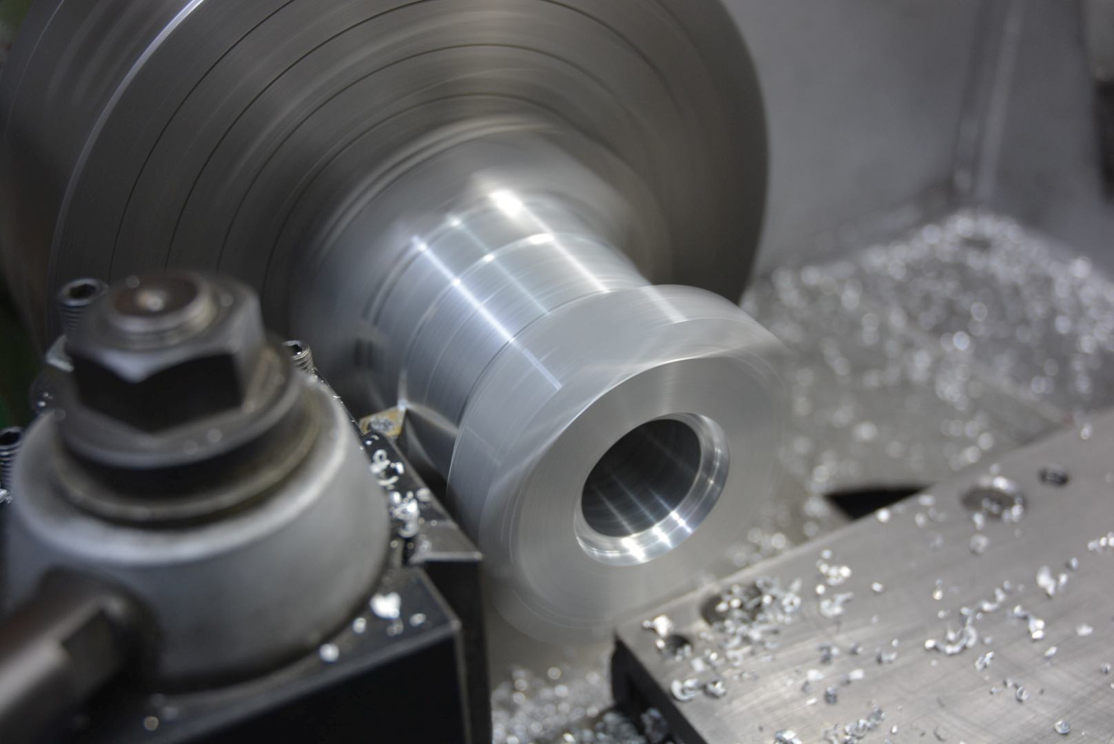
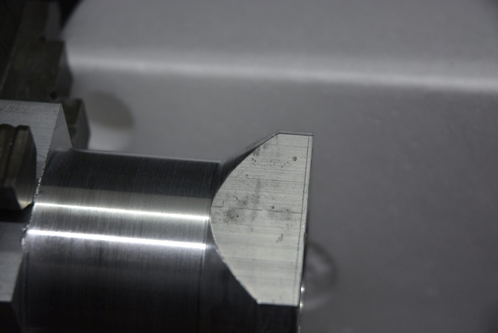
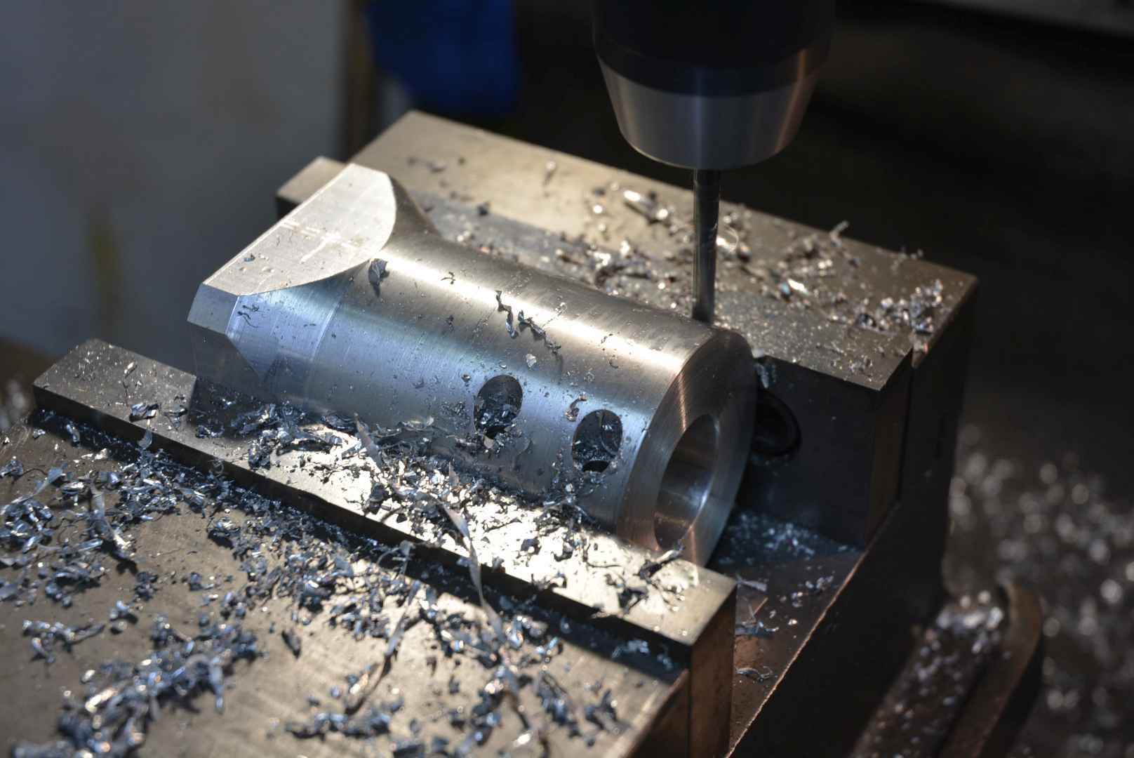
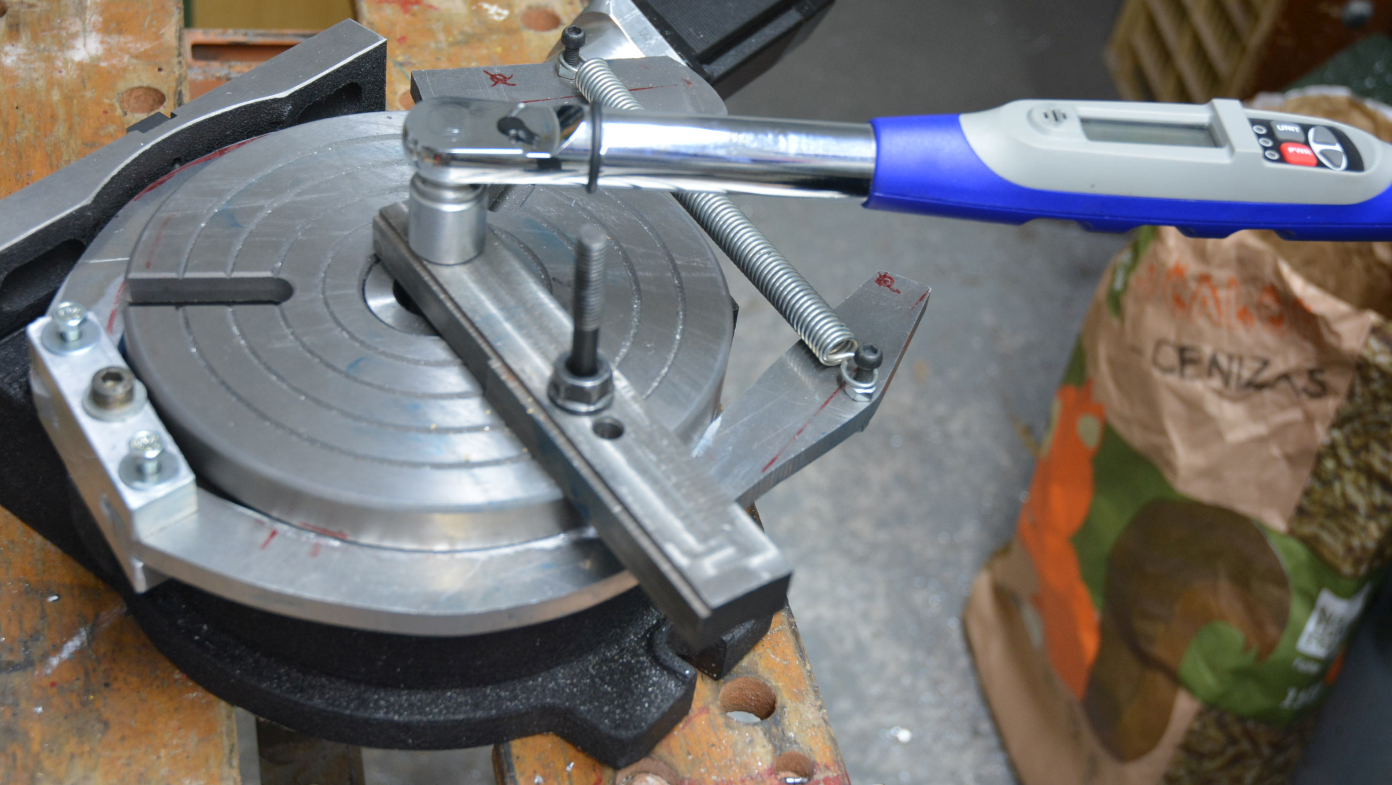
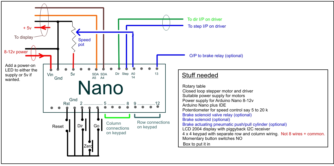
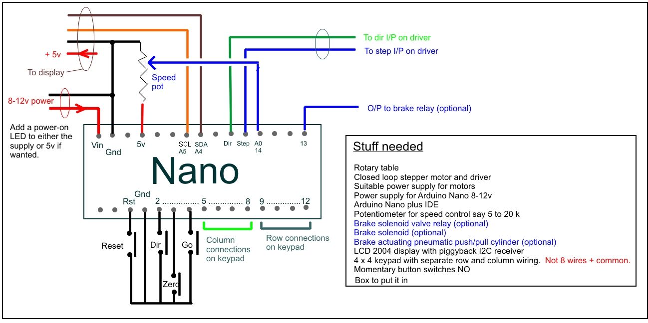
    On simple projects like this I almost never draw a schematic and I do not have one for this tool. I will recreate one by reverse engineering the code and I'll post that soon. In the meantime here are a bunch more photos with minimal explanation on most.

    Motorized rotary table-rotab003.jpg Motorized rotary table-rotab002.jpg Motorized rotary table-rotab006.jpg Click images for full size.

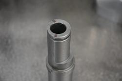
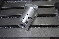
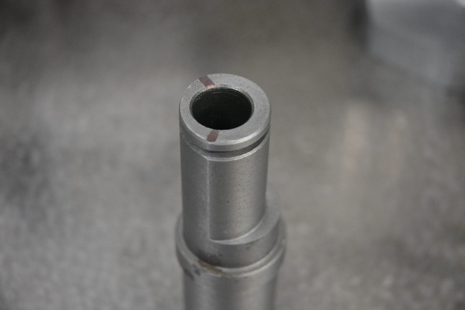
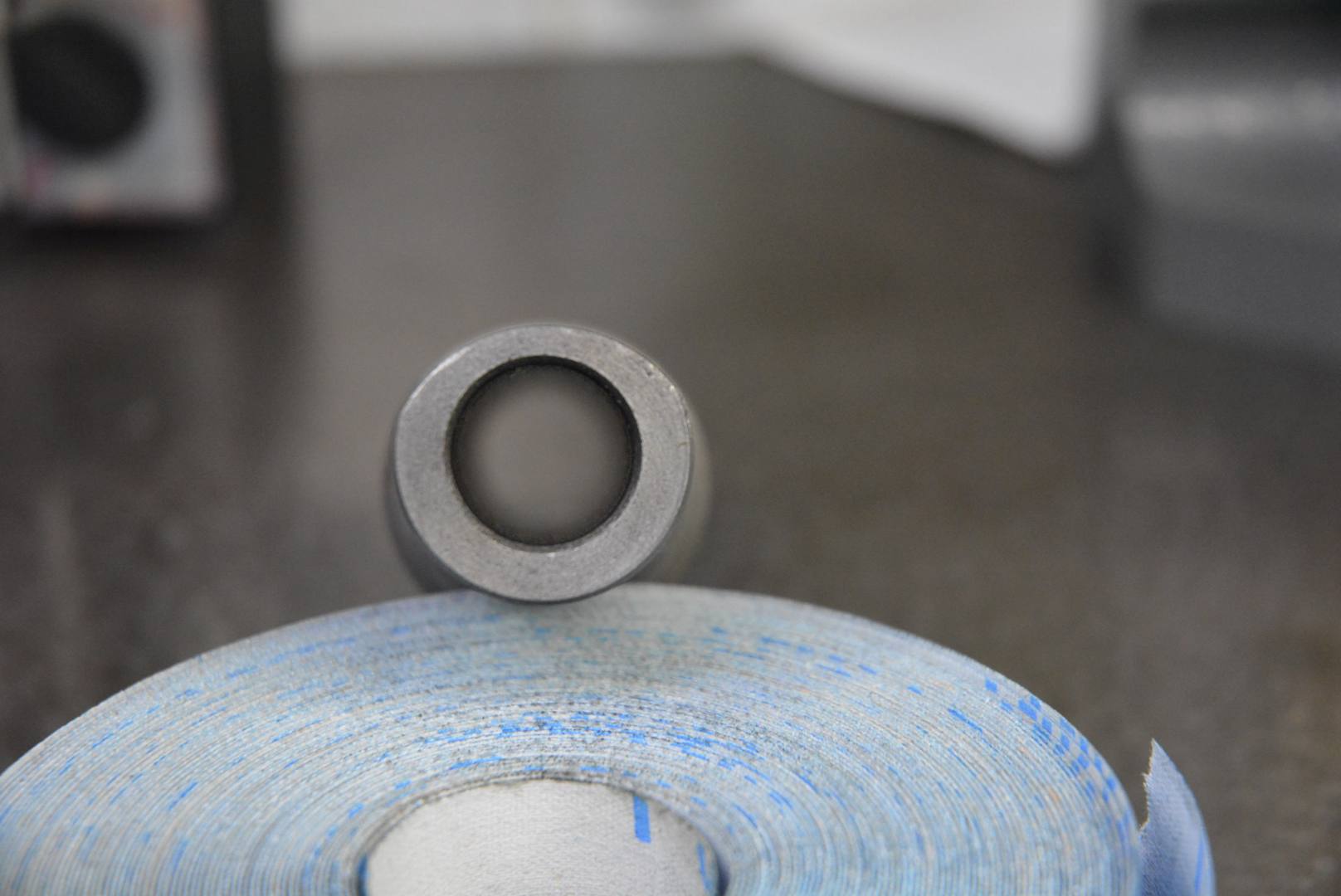
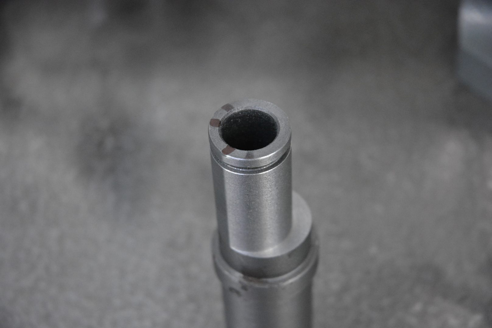
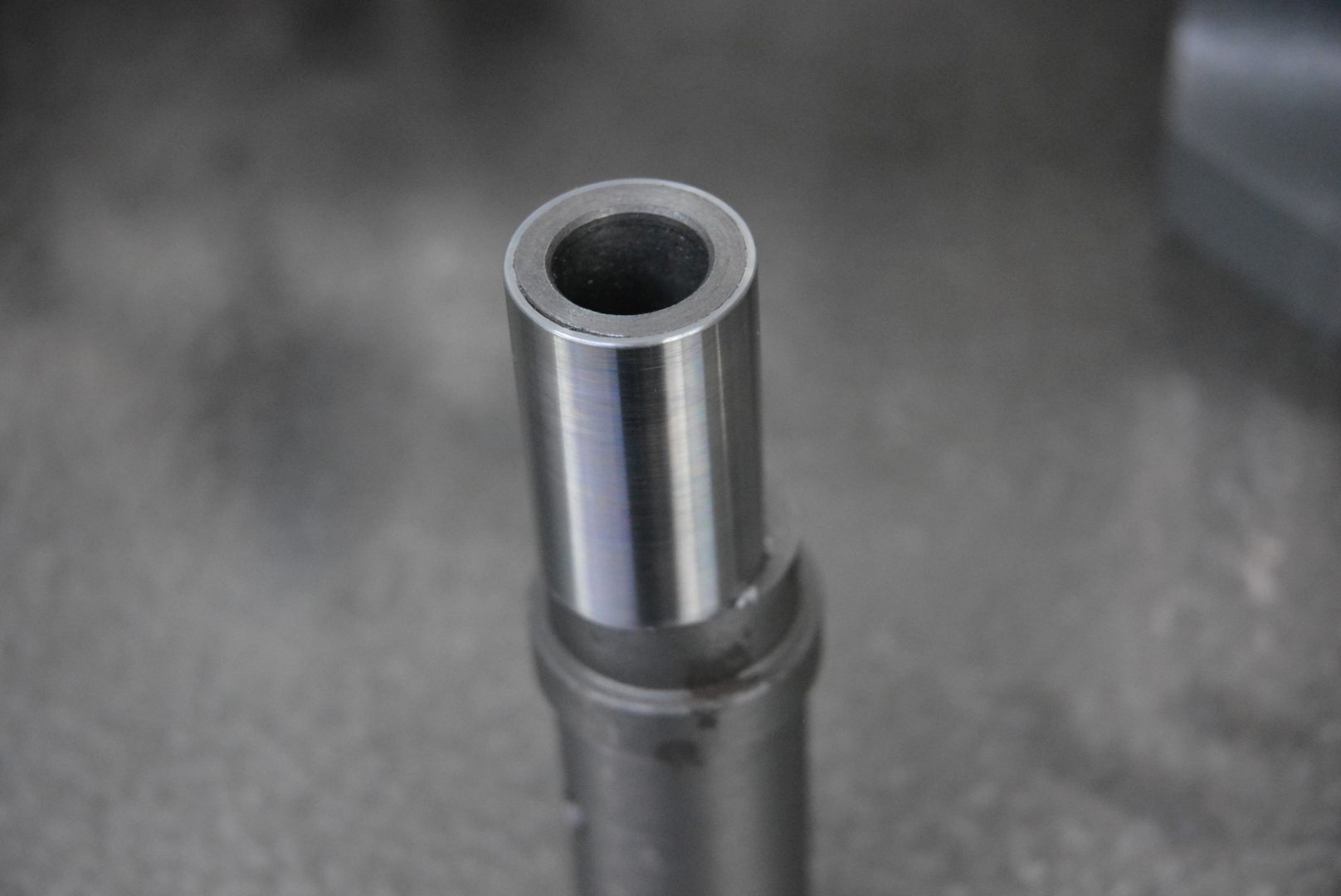
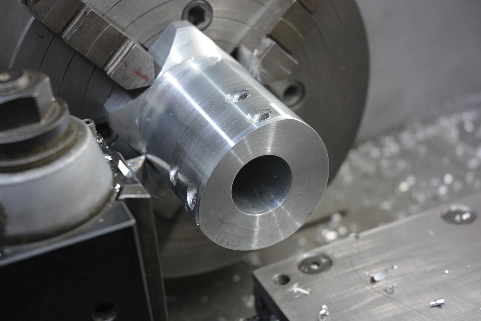
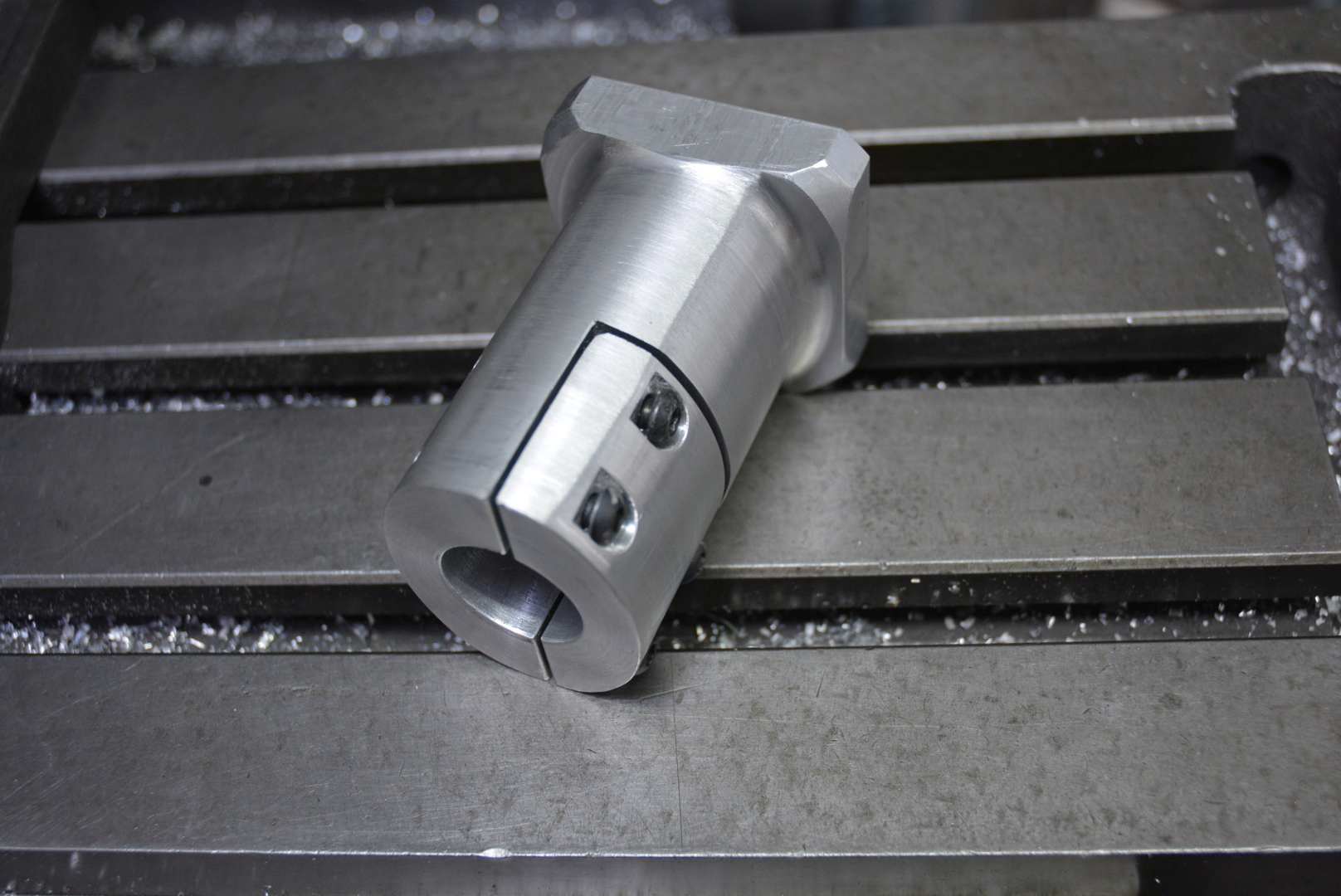
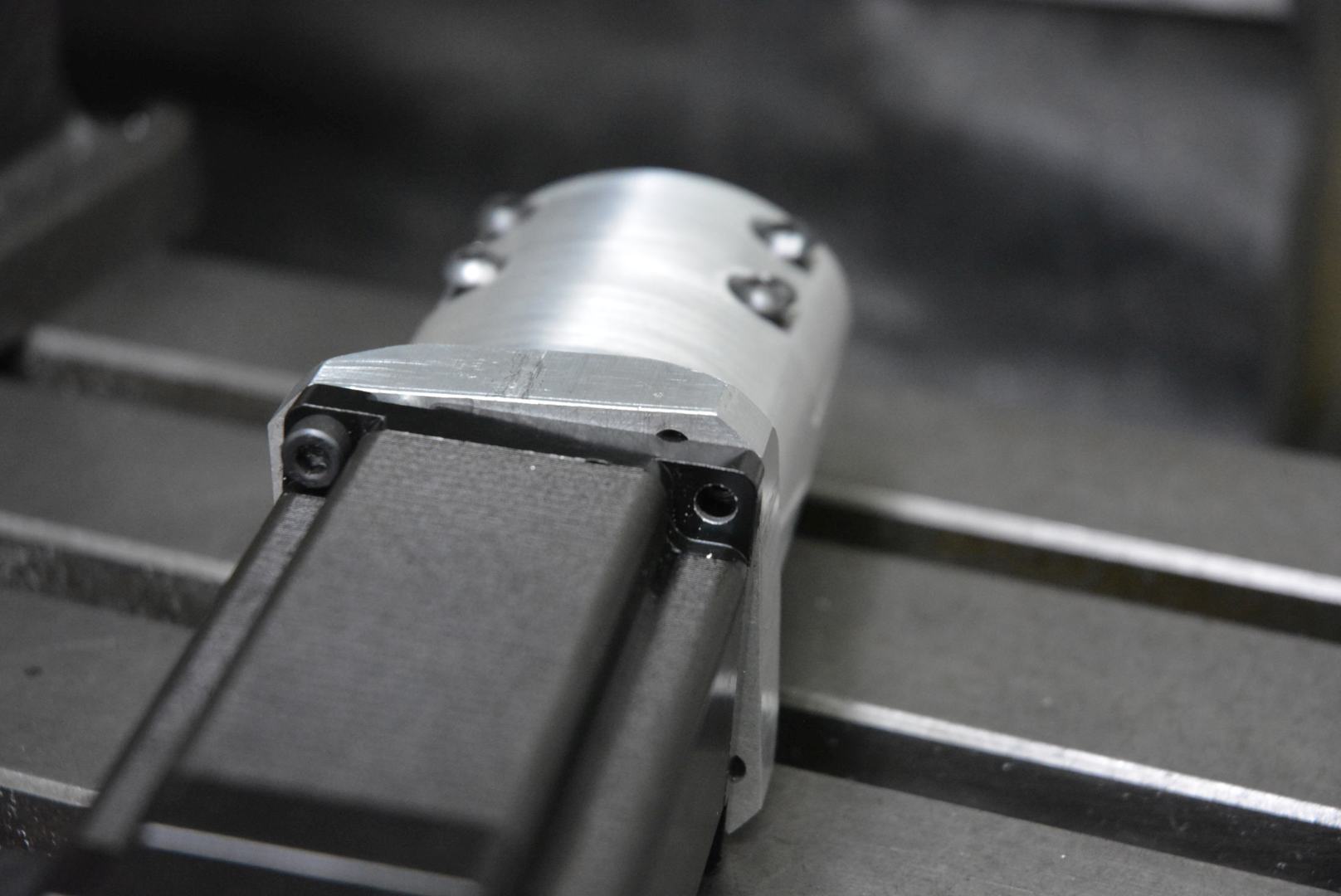
    The first pic. shows the input spindle bush which has only been machined concentric with the bore for part of the circumference, as marked. I needed to use that for a location and wanted the OD to be concentric all the way around. That piece is cast iron and I did not want to machine it down too thin. So I just took enough off to locate a steel sleeve, the remaining gap was filled with epoxy. Here is the sleeved part. This piece is critical and is highly loaded because it takes the overhung weight of the motor.

    Motorized rotary table-rotab007.jpg

    Motorized rotary table-rotab011.jpg Motorized rotary table-rotab013.jpg Motorized rotary table-rotab014.jpg

    Motorized rotary table-rotab016.jpg Motorized rotary table-rotab020.jpg Motorized rotary table-rotab023.jpg

    Motorized rotary table-rotab026.jpg Motorized rotary table-rotab029.jpg Motorized rotary table-rotab030.jpg

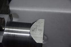
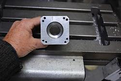
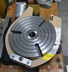
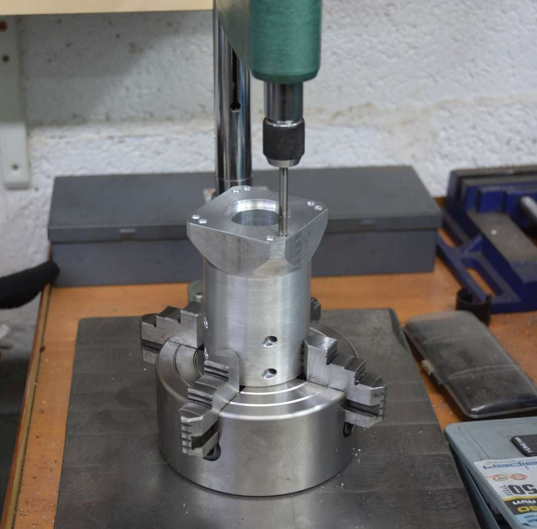
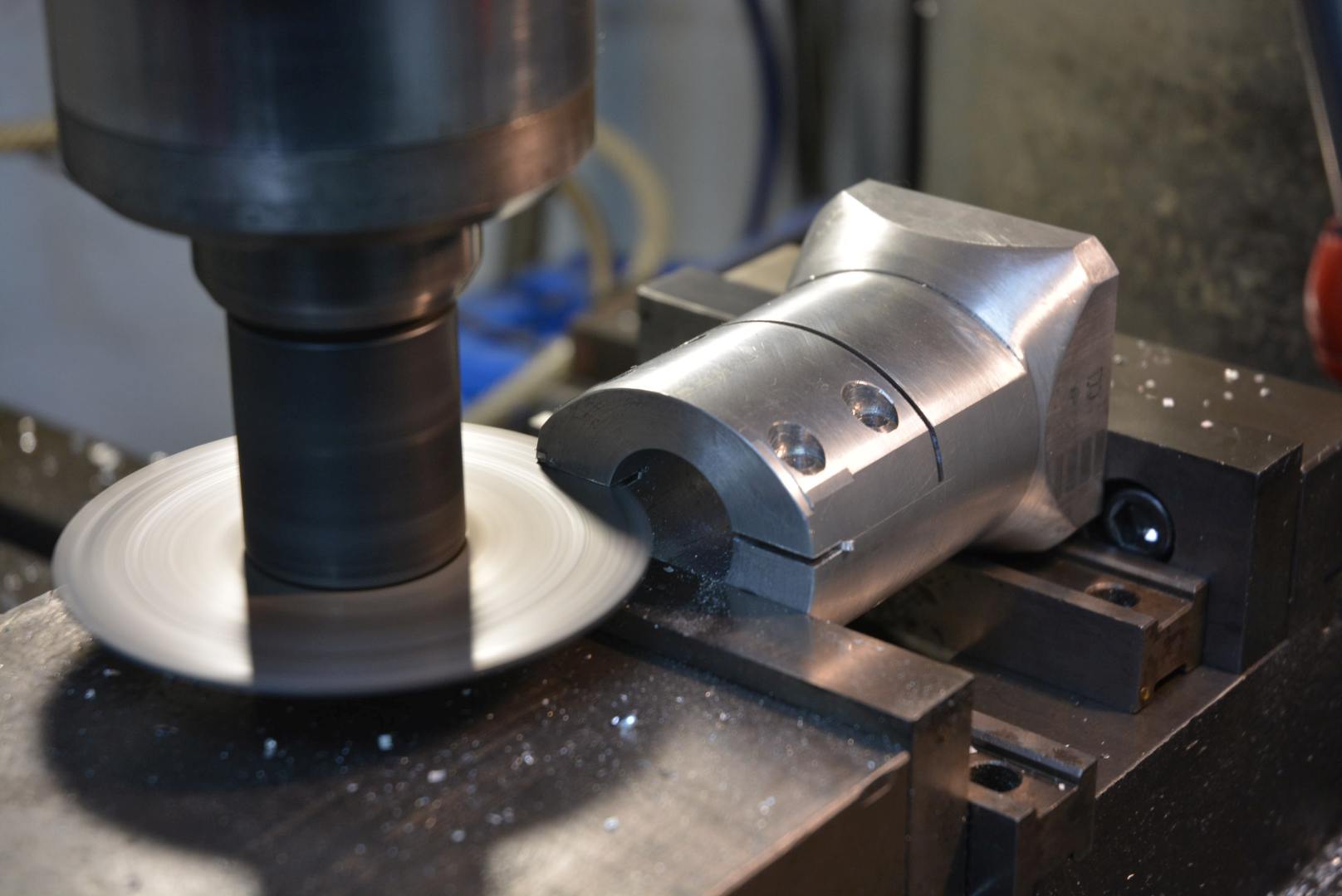
    At the time of building I did not know if I would end up using a Nema23 or 24 motor. They are very similar in size but the mounting holes are on a slightly different PCD. By drilling and tapping two sets of holes, each set with an angular offset from the other I could accommodate either motor.

    Motorized rotary table-rotab039.jpg Motorized rotary table-rotab040.jpg Motorized rotary table-rotab042.jpg

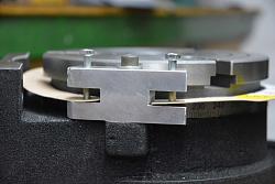
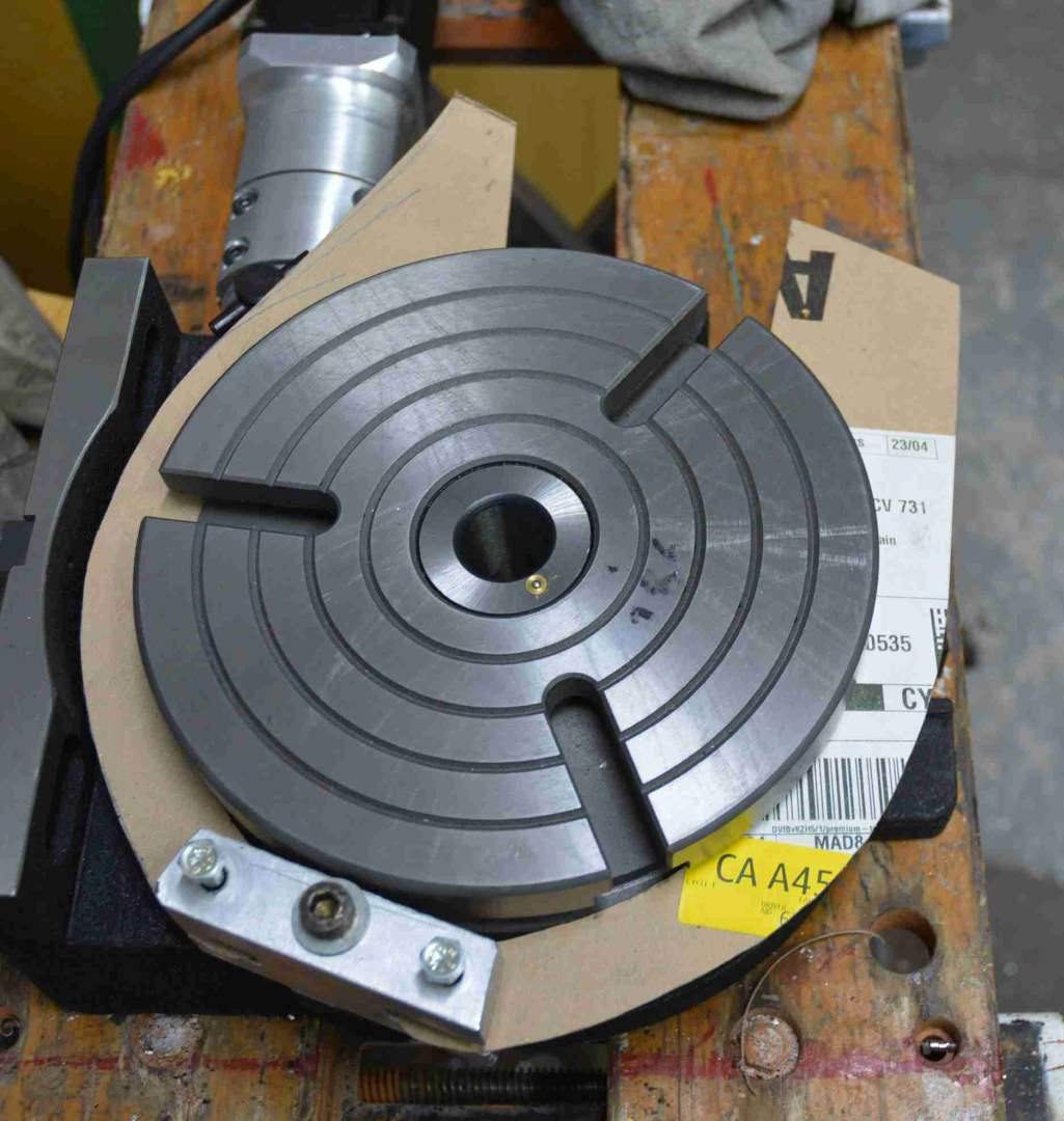
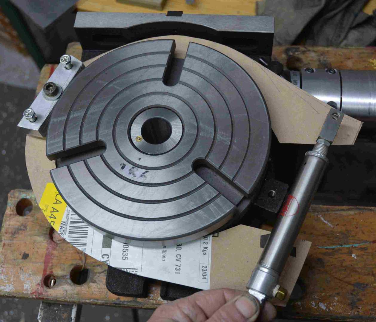
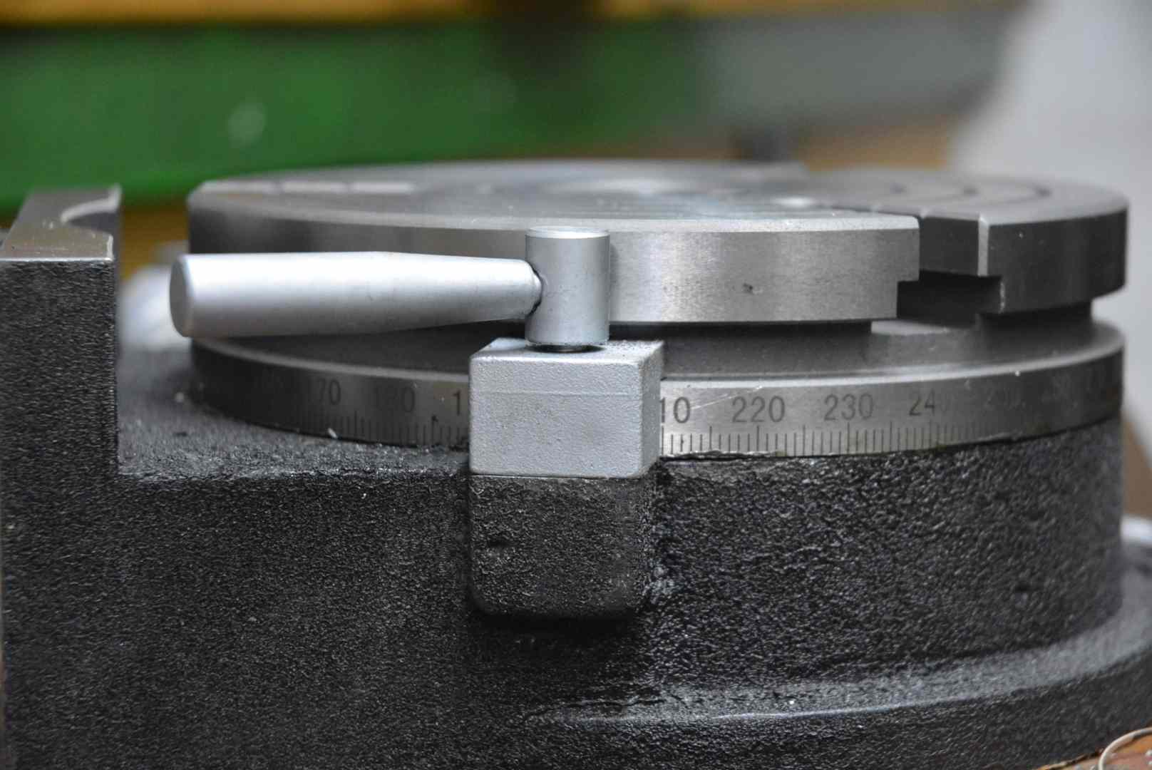
    These types of rotary table allow adjustment of the worm to control backlash, but there will always be some unless the adjustment is so tight that it is difficult to turn. Backlash is not too much of a positioning problem if you always drive the table in the same direction throughout a particular job. A brake is a reasonable solution and most come with simple clamps 180 degrees apart. I know some people who have made motorised tables put various forms of actuator on these clamps but I do not like that. I am sure that the clamp threads will have a short life. I have made an insideout drum brake pneumatically operated and the software automatically controls that via a solenoid valve. I do not seem to have photos of the finished brake (it was the last piece to be made) so I show the cardboard templates instead.

    Motorized rotary table-rotab038.jpg Ok for manual use but not so good for powered use.

    I'll make another post about the control system. It is dead simple.

    186 More Best Homemade Tools eBook

  2. The Following 7 Users Say Thank You to tonyfoale For This Useful Post:

    desbromilow (Jun 7, 2023), Home-PC (Jun 9, 2023), Jon (Jun 5, 2023), metric_taper (Jun 5, 2023), mwmkravchenko (Jun 7, 2023), Ralphxyz (Jun 7, 2023), schuylergrace (Jun 7, 2023)

  3. #12
    Supporting Member metric_taper's Avatar
    Join Date
    Mar 2017
    Location
    Marion, Iowa
    Posts
    586
    Thanks
    228
    Thanked 257 Times in 153 Posts

    metric_taper's Tools
    Very easy to read code.
    Thank you Tony Foale.

    Interesting brake add on. I assume you had some sort of friction material attached to the brake arms.

    2000 Tool Plans

  4. #13
    Supporting Member tonyfoale's Avatar
    Join Date
    Nov 2016
    Location
    Spain
    Posts
    1,566
    Thanks
    690
    Thanked 2,646 Times in 709 Posts

    tonyfoale's Tools
    Quote Originally Posted by metric_taper View Post
    Very easy to read code.
    Thank you Tony Foale.

    Interesting brake add on. I assume you had some sort of friction material attached to the brake arms.
    No friction material, just aluminium. Remember this is a holding brake only. It only gets applied or released when the table is stationary. There is never any rubbing.

  5. #14
    Supporting Member Saltfever's Avatar
    Join Date
    Apr 2012
    Location
    NorCal
    Posts
    355
    Thanks
    391
    Thanked 126 Times in 86 Posts

    Saltfever's Tools
    Nicely commented, Tony. For someone with zero experience with microprocessors I could even find the on/off code for the brake!

    I'm looking forward to the rest of your information.

  6. The Following User Says Thank You to Saltfever For This Useful Post:

    tonyfoale (Jun 8, 2023)

  7. #15
    Supporting Member tonyfoale's Avatar
    Join Date
    Nov 2016
    Location
    Spain
    Posts
    1,566
    Thanks
    690
    Thanked 2,646 Times in 709 Posts

    tonyfoale's Tools
    Quote Originally Posted by metric_taper View Post

    Interesting brake add on. I assume you had some sort of friction material attached to the brake arms.
    I did have a photo after all of the real brake shoes. Here it is showing torque testing of the brake.

    Motorized rotary table-rotab046.png

  8. #16
    Supporting Member tonyfoale's Avatar
    Join Date
    Nov 2016
    Location
    Spain
    Posts
    1,566
    Thanks
    690
    Thanked 2,646 Times in 709 Posts

    tonyfoale's Tools
    Quote Originally Posted by Saltfever View Post
    Oh my, Tony you could be at the F-1 race this weekend and here you are posting to HMT!
    I was the works manager for a F1 team in the early 1970s just at the start of serious aero add-ons and Bernie's influence which coincided with the the end of interesting racing. I have no interest at all in F1, it is so boring. If you want good racing have a look at motoGP. Better yet the TT which has just finished.

  9. #17
    Supporting Member tonyfoale's Avatar
    Join Date
    Nov 2016
    Location
    Spain
    Posts
    1,566
    Thanks
    690
    Thanked 2,646 Times in 709 Posts

    tonyfoale's Tools
    It goes against my usual way of working but I have drawn a schematic. If you are contemplating making something like this then here is not the place to ask about how to load the code or connect to an Arduino. Arduino.cc is full of helpful tutorials and guides on all of that basic stuff.

    The motor and driver need to be sized to match the size of your table. I STRONGLY advise using a closed loop stepper motor. Nowadays they are not all that much more expensive than open loop but they are just so much better. The driver and motor are often sold as a pair and I have seen some offers with driver, motor and power supply as a package. I made my own motor power supply so I got the motor and driver only. You will need an 8 to 12 v DC power supply for the Arduino. This has a very low power requirement and you could use a 9 v DC wall wart or similar.

    PS. I just noticed that on the drawing in the BOM I wrote "Brake solenoid" that should read "Brake solenoid valve".

    Motorized rotary table-rotabschematic.jpg Click for full size.

  10. The Following 2 Users Say Thank You to tonyfoale For This Useful Post:

    Little Rabbit (Jun 12, 2023), Saltfever (Jun 13, 2023)

  11. #18
    Supporting Member metric_taper's Avatar
    Join Date
    Mar 2017
    Location
    Marion, Iowa
    Posts
    586
    Thanks
    228
    Thanked 257 Times in 153 Posts

    metric_taper's Tools
    Quote Originally Posted by tonyfoale View Post
    I did have a photo after all of the real brake shoes. Here it is showing torque testing of the brake.

    Click image for larger version. 

Name:	RoTab046.png 
Views:	92 
Size:	1.66 MB 
ID:	45593
    Looks like a test setup to see what sort of force (provided by the test spring) was needed. Since you used an air cylinder to provide this force, and I assume air pressure of 90psi (6bar), how large a diameter cylinder did you use to get the brake lock force you wanted?

  12. #19
    Supporting Member tonyfoale's Avatar
    Join Date
    Nov 2016
    Location
    Spain
    Posts
    1,566
    Thanks
    690
    Thanked 2,646 Times in 709 Posts

    tonyfoale's Tools
    Quote Originally Posted by metric_taper View Post
    Looks like a test setup to see what sort of force (provided by the test spring) was needed. Since you used an air cylinder to provide this force, and I assume air pressure of 90psi (6bar), how large a diameter cylinder did you use to get the brake lock force you wanted?
    25 mm diam and 25 mm stroke.

  13. #20
    Supporting Member tonyfoale's Avatar
    Join Date
    Nov 2016
    Location
    Spain
    Posts
    1,566
    Thanks
    690
    Thanked 2,646 Times in 709 Posts

    tonyfoale's Tools
    In comment #17 there is an error in the schematic. Pin A5 schould be labelled SCL not SDA as shown. Here is the corrected version.

    Motorized rotary table-rotab_schematic.jpg Click on it for full size

  14. The Following User Says Thank You to tonyfoale For This Useful Post:

    Saltfever (Jul 9, 2023)

Thread Information

Users Browsing this Thread

There are currently 1 users browsing this thread. (0 members and 1 guests)

Bookmarks

Posting Permissions

  • You may not post new threads
  • You may not post replies
  • You may not post attachments
  • You may not edit your posts
  •