 LinkBack URL
 About LinkBacks
I have been using this over the past couple of days to make a motorcycle clutch.
Click for full size.


I have been using this over the past couple of days to make a motorcycle clutch.


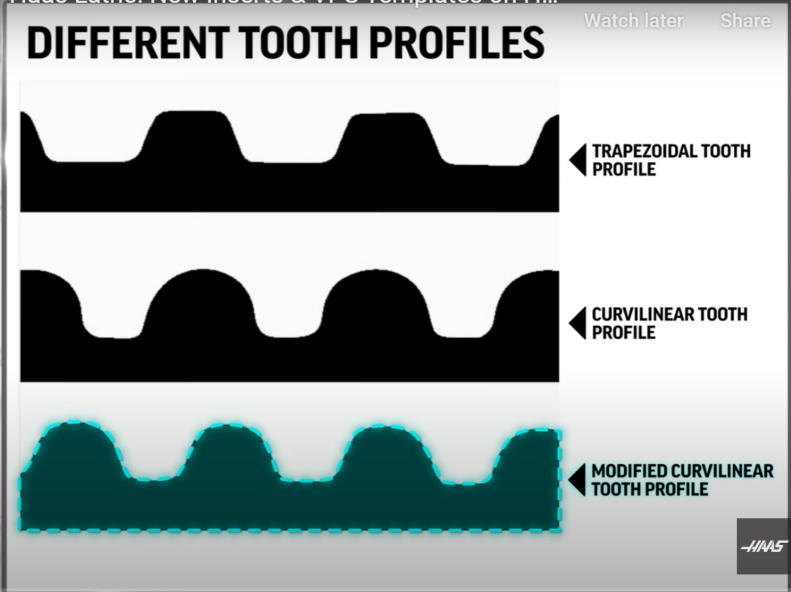
I realize (realise) you are just drilling the holes, Tony but seeing your photo of the timing belt hub reminded me that Hass came out this week with a carbide insert for forming the tooth profile. The geometry is here but I found their video quite interesting. Around 0:42 they describe the 3 popular tooth shapes. I instantly thought of your ELS and other possibilities, as well as indexing the lathe spindle on a manual lathe. So many interesting things to do!
I tried to post a clickable link for the video but it looks like YouTube has taken control and now plays the video (in large size). I find it annoying because it clutters up the post so I shoved it to the bottom of this post.
.
Last edited by Saltfever; Mar 23, 2024 at 02:06 AM.
You have lost me here.Originally Posted by Saltfever

Firstly, Drilling what holes?
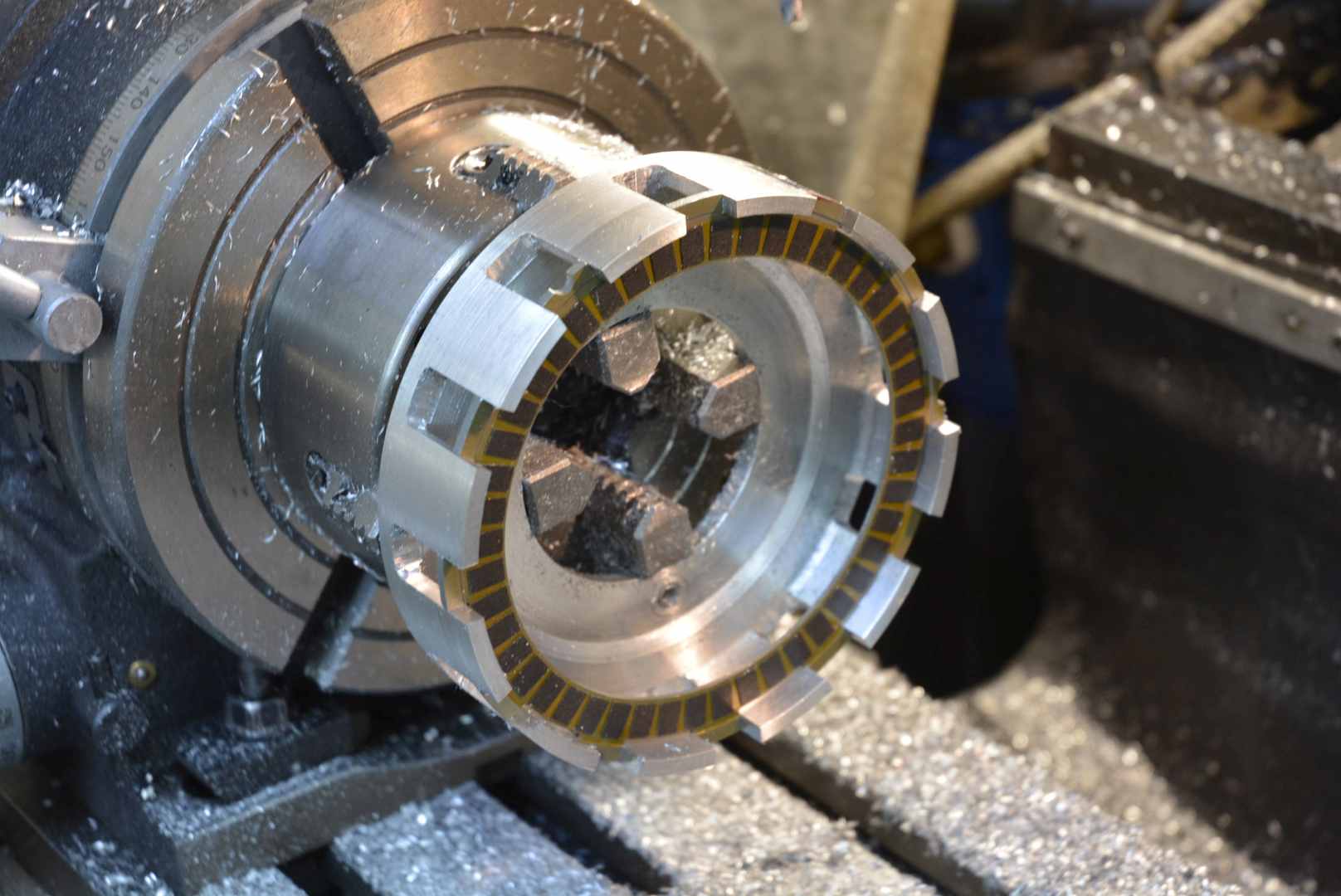
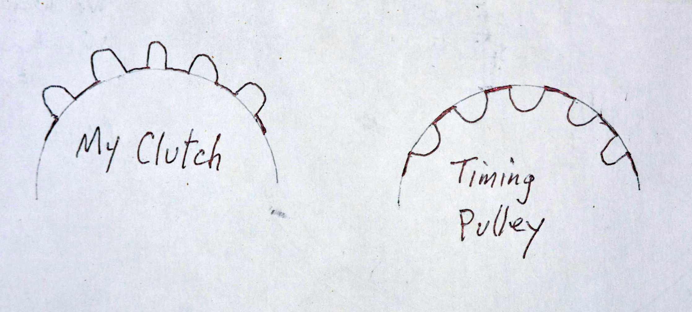
Secondly, I think that you are confusing a clutch hub with a timing belt pulley. Those teeth are convex shape whereas pully teeth are concave. As in the Haas video I did use a form tool for that. I modified my T&C grinder Homemade Tool & Cutter grinder (with a difference). to be able to make the tool. The Haas video formed the teeth by slotting whereas I did it by milling.
Just to be clear, this work was done on a mill not a lathe.
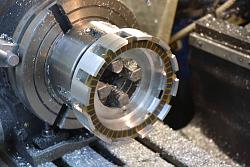
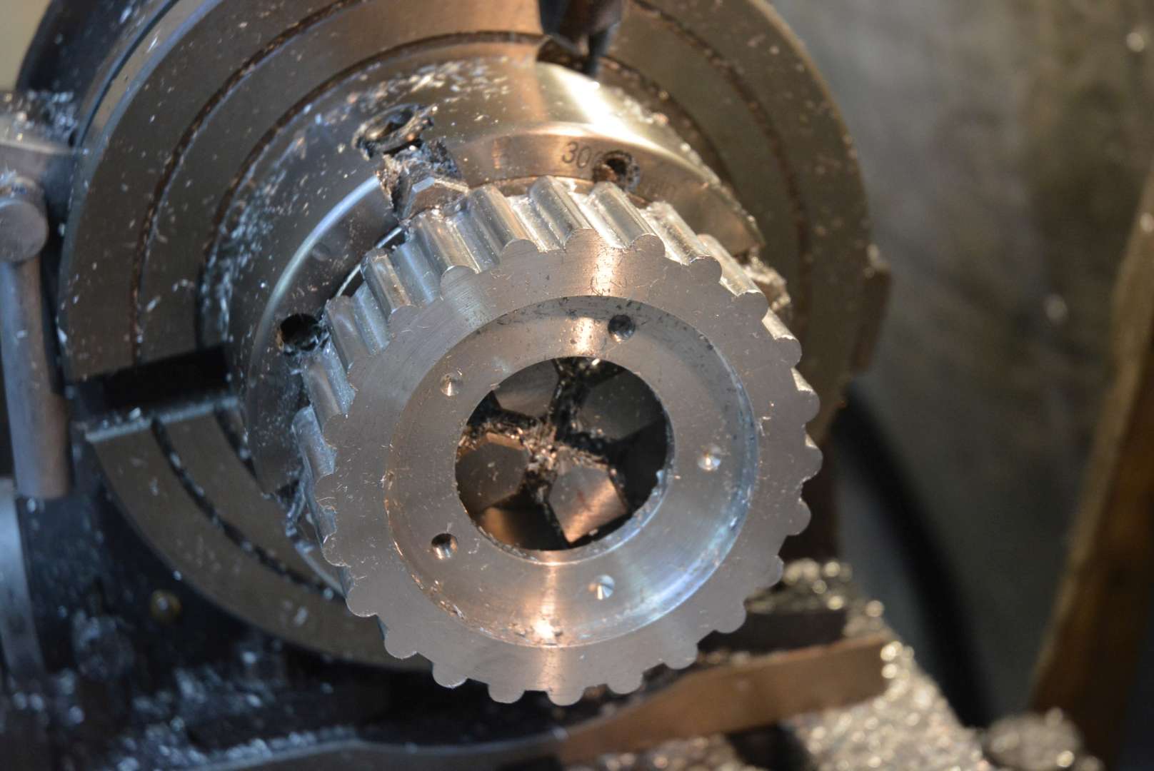
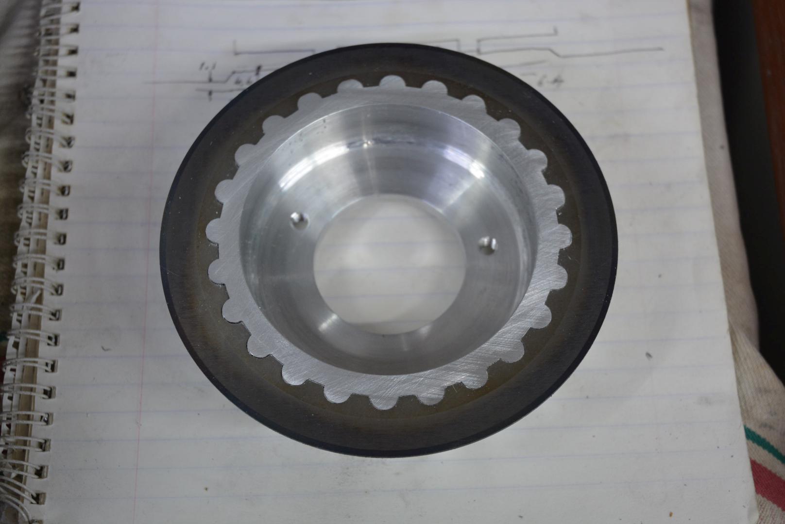
The tooth shape had to precisely fit an off the shelf clutch plate as shown here. It was a tricky job because there was no easy reference off the tool from which to set the DOC. I was unsure how good a job I could make of it so I made a test example using 1/4" plate, so as not to risk the real thing.
Test piece. Click for full size.
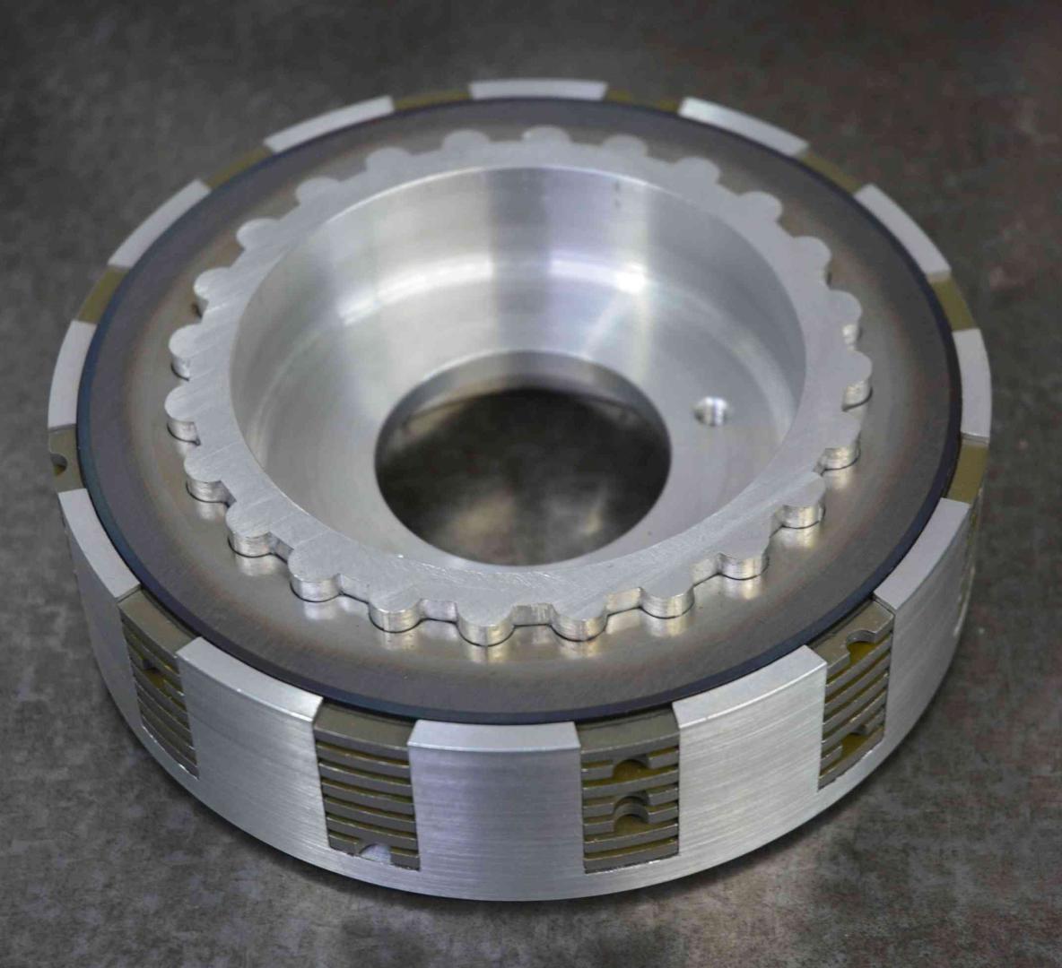
Clutch plate on real piece.
Assembled clutch pack.
Last edited by tonyfoale; Mar 23, 2024 at 03:07 PM.
Opps, sorry for the confusion, Tony. I saw the partially drilled hub and thought you were indexing to drill the bolt circle. The teeth looked so good I thought you purchased a timing pulley that you were modifying. I didn't think you were cutting them. I should have known better!And since some motorcycles use a drive-belt-timing-pulley I wasn't thinking of a clutch hub even though your other pic clearly displayed that. Thought maybe you were developing two different improvements at the same time.
The video reminded me your ELS would be a good application if an indexing scheme was worked out for a manual lathe. Both of what I want to do eventually.
PS: Your hub teeth look like a timing curvilinear-tooth-profile which added to my confusion. Oh well ...
Last edited by Saltfever; Mar 23, 2024 at 04:03 PM. Reason: PS: added
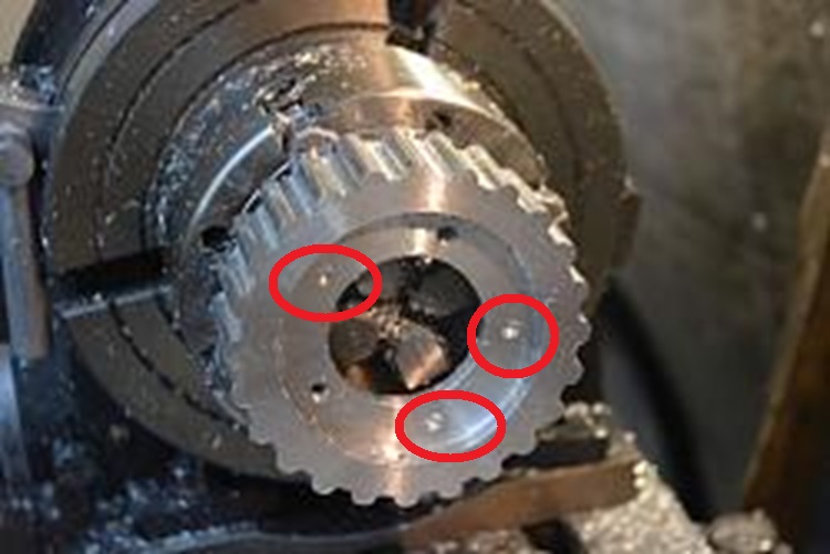
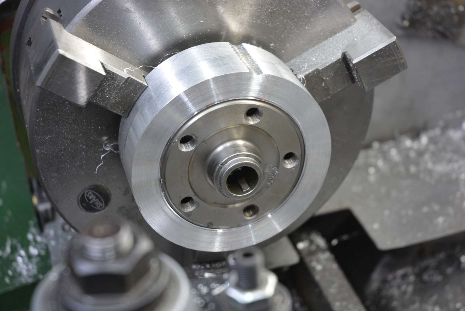
The holes were just spotted through from the mounting plate. Only two had been drilled and tapped just to hold the mounting plate while I clocked true.
The drum was clocked true to the mounting plate in the lathe and the outer surface machined as a reference.
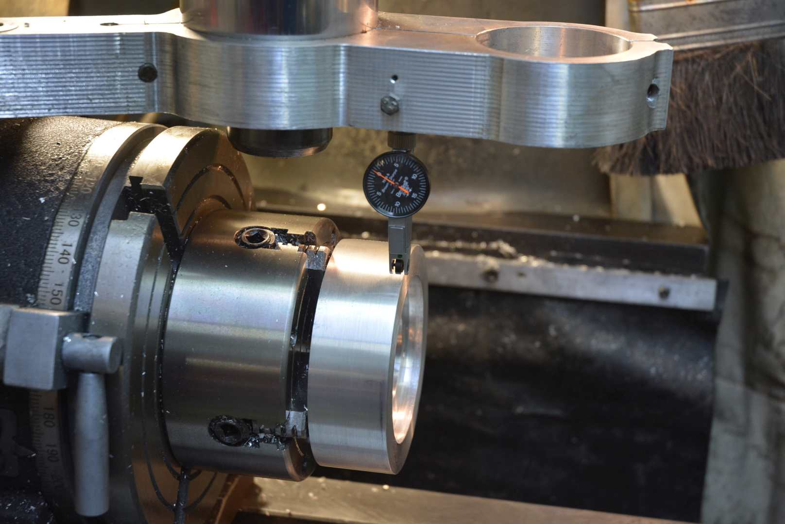
The outer surface was then clocked true on the rotab.
You only need to add a closed loop stepper to the spindle and add a few lines to the software.
The tooth profiles are close to being inverses of each other. It is almost trivial to grind up a tool for making pulleys, the shape I needed was a touch more difficult.
And maybe a brake too?. Don't know if I would trust the stepper to "hold" during the shaping?
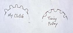
Not sure I'm understanding your "inverse" profile. Your teeth looked curvilinear. Are you indicating you modified that shape?
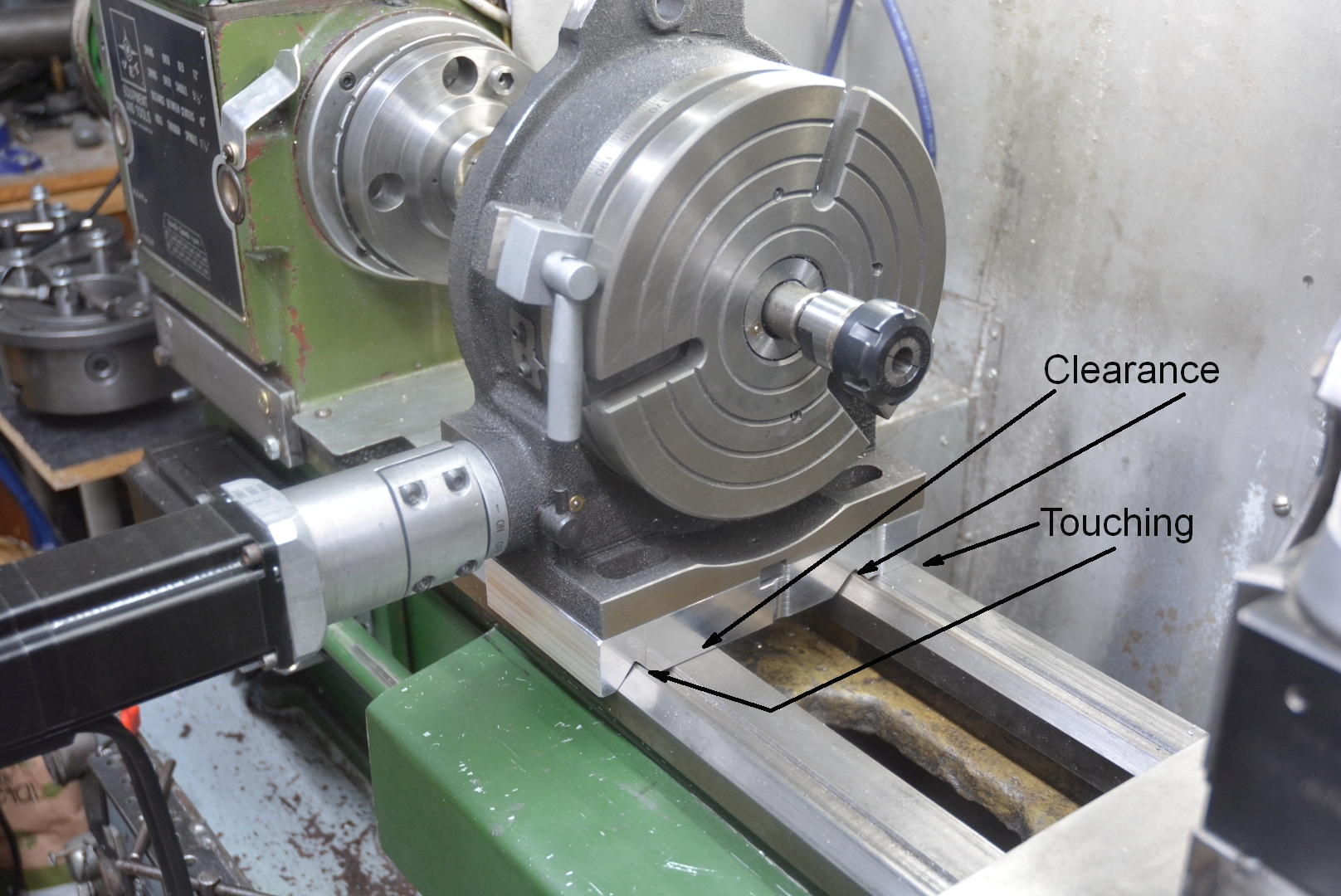
The stepper is not a problem for holding, just use a big enough one. Any holding problem will come from any backlash between the motor and the spindle. For example, the worm and wheel driving system on the rotab. As described in my original post I made an automatic brake for this. That was fine when the rotab was horizontal but when I came to make this clutch I found out that the mounting bolts wanted to occupy the same space as the brake. The bolts won.
About the profiles being inverses of each other, maybe this will help.
I think the time differential has us out of sync! LOL
I was thinking of your ELS as the driver to shape the teeth of bar stock chucked in a lathe as seen in the Haas video. In that case the lathe would need an indexing plate and someway to lock the lathe spindle, or as you indicate, incorporate a stepper to do the indexing and it would be strong enough to hold it. There is no rotab attached to the lathe.
The tooth profile I was discussing is the Gates standard timing belt as show in the Haas video. Here is a screen shot from the video.
However, your sketch looked like the old HTD style that I remembered and that caused me to look for other "standards". Wow, I didn't realize there was so many un-standards today! Lol Here is a link that I think covers most of them.
Anyway, many thanks for your patience and help. I now understand exactly what you are doing.
The HTD is the inverse of what I needed.
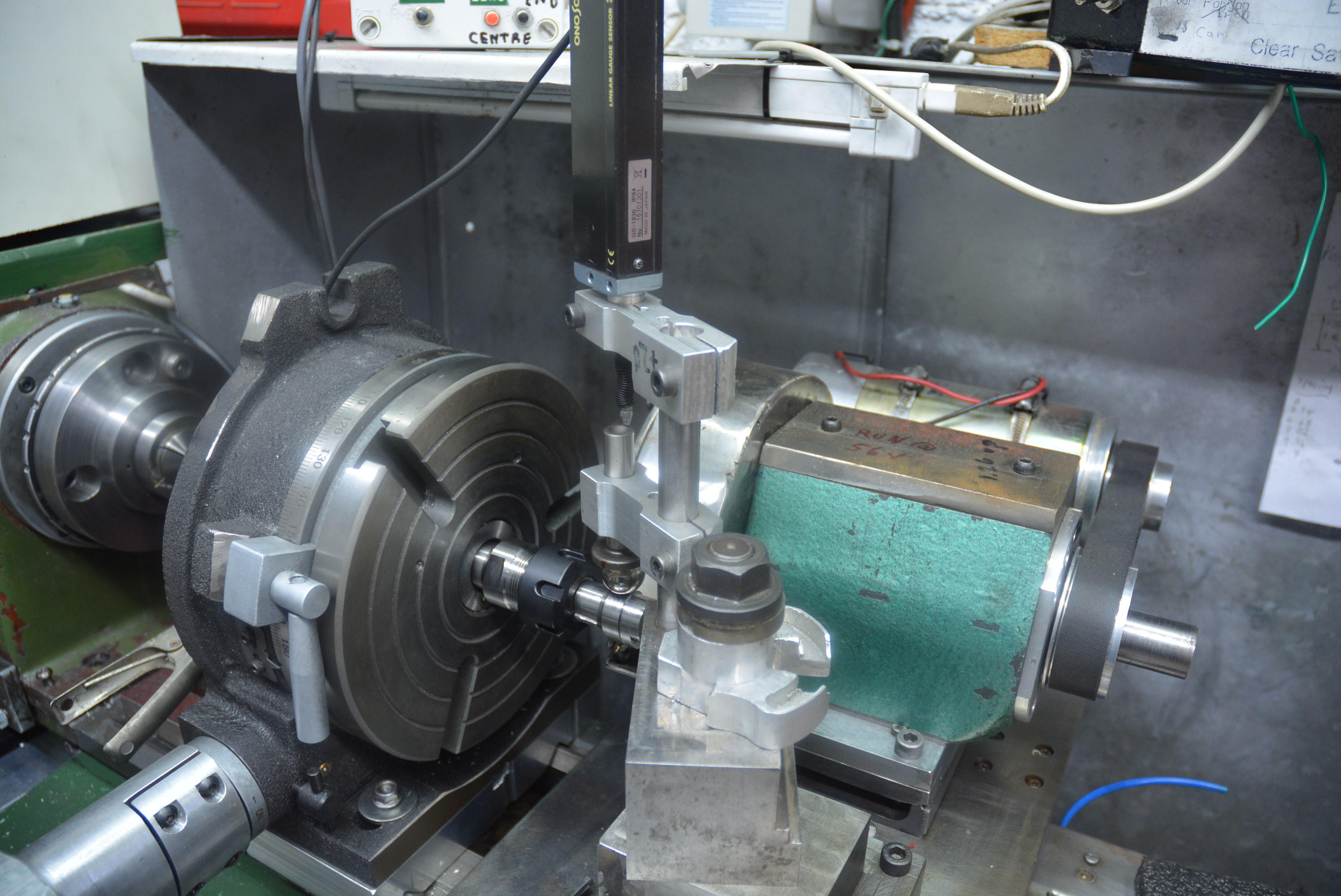
Well I guess that I have done what you are talking about. I have been converting my electronic lathe to do cam grinding but it was not straight forward to get my lathe spindle to turn with a variable speed over each revolution, and then there is the question of adding a very low resolution encoder to it. In the middle of the night it hit me. Replace the lathe headstock with the motorised rotab.

Click for full size
Here is a 3 minute unlisted video as a teaser before I find the time to document it all.
and with sparks
https://www.dropbox.com/scl/fi/pfswb...=emvk6j0b&dl=0
https://www.dropbox.com/scl/fi/4inw4...=6iv13kxa&dl=0
Last edited by tonyfoale; Oct 30, 2024 at 11:35 AM.
Jon (Dec 1, 2024), metric_taper (Oct 30, 2024), mwmkravchenko (Oct 31, 2024), Saltfever (Oct 31, 2024), Tonyg (Oct 31, 2024)
There are currently 2 users browsing this thread. (0 members and 2 guests)
 Posting Permissions


 Reply With Quote
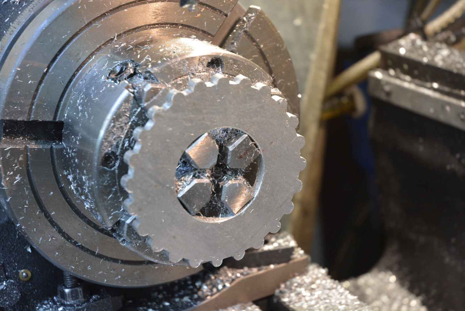
Bookmarks