This is how I spend my weekends.. I am such a nerd..
https://www.youtube.com/watch?v=c9tWtEG1Exc
Printable View
This is how I spend my weekends.. I am such a nerd..
https://www.youtube.com/watch?v=c9tWtEG1Exc
Definitely an interesting use of a boring tool. Care to share the code for generating the toolpath?
First couple tries in plastic. (painfully slow - just testing) (and the hole size should be way closer to the inscribed polygon diameter...)
https://youtu.be/X1ma_TsItMk
http://electronicsam.com/images/gree...310_190102.jpg
Quote:
Originally Posted by dagrizz
This is the hal component for linuxcnc... WIP use at your own risk.
Code:// This is a component for Linuxcnc HAL
// Copyright 2020 Sam Sokolik <samcoinc@gmail.com>
//
// This program is free software; you can redistribute it and/or modify
// it under the terms of the GNU General Public License as published by
// the Free Software Foundation; either version 2 of the License, or
// (at your option) any later version.
//
// This program is distributed in the hope that it will be useful,
// but WITHOUT ANY WARRANTY; without even the implied warranty of
// MERCHANTABILITY or FITNESS FOR A PARTICULAR PURPOSE. See the
// GNU General Public License for more details.
//
// You should have received a copy of the GNU General Public License
// along with this program; if not, write to the Free Software
// Foundation, Inc., 51 Franklin Street, Fifth Floor, Boston, MA 02110-1301 USA.
component polygon "Create a spindle synced motion that carves a polygon using eoffset inputs. Assumes positive rotation.";
pin in bit enable;
pin in unsigned numsides=3 "Number of sides in the polygon";
pin in float inscribedradius=1 "inscribed radius of the polygon";
pin in float cutterdiam "cutter diameter";
pin in float eoffsetscale "scale that eoffset is set to.";
pin in float toolang "angle difference between index and actual tool poition";
pin in float spindlepos "Spindle position scaled to 1 per rev";
pin out float spindlerad "Spindle postion in radians";
pin out float polyradius "radious of the polygon at given spindle position";
pin out float xoffset "x offset to send to offset componant";
pin out float yoffset "y offset to send to the offset componant";
pin out signed xeoffset "x eoffset output";
pin out signed yeoffset "y eoffset output";
pin out bit isindex "set index enable only once";
pin io bit indexenable "hooked to index enable of encoder";
function _;
license "GPL";
;;
#include <rtapi_math.h>
#define PI 3.14159265358979323846
float spinang;
float scale;
float spinangoffset;
if (!enable) {
xoffset=0;
yoffset=0;
xeoffset=0;
yeoffset=0;
isindex = false;
return;
}
// only set index enable once
if (enable && !isindex) {
isindex = true;
indexenable = true;
return;
}
// wait for spindle index before actually enabling
if (enable && isindex && indexenable){
return;
}
//convert spinangoffset to ratio.. for adding to spindle pos - plus a couple rotations
//so the spindle position isn't negative
spinangoffset = (toolang/360)+2;
//formual I found is for circumscribed - convert to inscribed - makes more sense.
scale=inscribedradius/cos(PI/numsides);
spinang = ((spindlepos + spinangoffset) - (int)(spindlepos + spinangoffset))*2*PI;
polyradius = (cos(PI/numsides)/cos((fmod(spinang, (2*PI/numsides))-PI/numsides)))*scale-cutterdiam/2;
//actual offsets applied - could be used for offset componant.
xoffset = cos(spinang)*polyradius * -1;
yoffset = sin(spinang)*polyradius;
//counts for use with eoffset functionality
xeoffset = xoffset / eoffsetscale;
yeoffset = yoffset / eoffsetscale;
spindlerad = spinang;
OK, that is COOL
: - )
Helps to have a CNC mill.
That is only part of it....
Quote:
Originally Posted by Ralphxyz
I have two questions;
1. Is the cutting mainly done by the XY table movement and the tool rotation is principally to present the tool at the required rake angle to the line of movement at each location on the path?
2. I am not familiar with Linux nor LinuxCNC, but I notice that you use a HAL file for the control. Is that because LinuxCNC does not use Gcode (I thought it did) or does a HAL file have advantages over Gcode?
I have been thinking of making a rotary broach but this is a much better approach for general work because you do not need a new broach for each size and shape of hole. A small and large boring bar is all you need for any size and shape. Now I'll have to write some Gcode, although a search of the net might turn up a wheel already invented by another.
Nice work BTW.
PS. I just realised that I'll have to add a rotary encoder to my spindle before I can follow your example. I have been meaning to do that for a while now, this is just the motivation needed.
Kind of - it would be impossible to keep the tool at the correct rake angle unless the tool had no thickness. Even then. The code just keeps the tool perpendicular to the center of the polygon. It works surprisingly well it seems (even if the tool isn't exactly at the right angle compared to the material.) So - half the time it is negative-ish and half the time it is positve-ishQuote:
Originally Posted by tonyfoale
The Hal component is what does the realtime stuff to do the motion. This can be controlled by gcode. The code is run 1000 times a second and reads the spindle position and calculates where x/y need to be. There are a bunch of parameters that you set (number of sides, cutter diameter, polygon radius and so on) I will get my gcode example to show you. The next step would be to do what is called a gcode re-map. So you could make it more user friendly. (one line of gcode maybe sets and enables the component)Quote:
Originally Posted by tonyfoale
thanks!Quote:
Originally Posted by tonyfoale
Yes I realised what was going on there, I did not know the timing of course. You cutting feeds and speeds are quite low, is that because of limitations of your mill or the software or was it to make a watchable video?Quote:
Originally Posted by skunkworks
That would be great. It would save reinventing that wheel.Quote:
Originally Posted by skunkworks
Getting back to the HAL file. Am I right it assuming that is what drives LinuxCNC and you use a Gcode to HAL converter to be able to use Gcode from a CAM programme or hand written.
The speeds are dictated by how much acceleration/speed the machine has. If I run the spindle a lot faster faster - the polygon will not look like a polygon... :)
Hal is linuxcnc's hardware abstration layer. It is sort of the interface between linuxcnc and the outside world. It allows you to create virtual circuits and logic to do as you please.
Quote:
Originally Posted by tonyfoale
Vertical lines are the effect from the low spindle encoder resolution.. Above tool path cut in aluminum..
http://electronicsam.com/images/gree...403_155600.jpg
Of course that begs the question, "what is the encoder resolution"?Quote:
Originally Posted by skunkworks
I love the twist. I guess that you repeat a subroutine with a coordinate transformation every spindle rotation?
Really neat.:clapping:
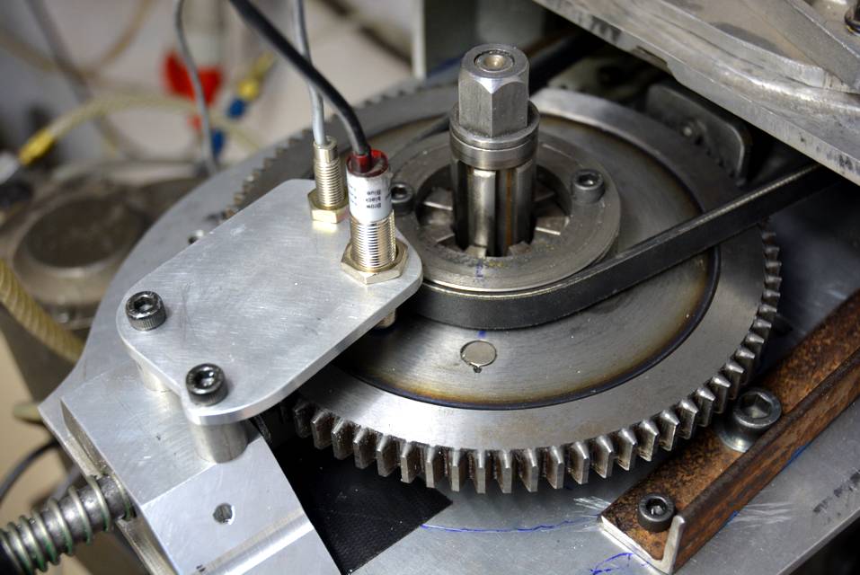
I used a some gear tooth sensors and a gear for the encoder.. It is only around 38 teeth so 152 counts per rev.. (which was fine for most threading/rigid tapping) I just added twist functionality to the comp. You send it the Deg/Rev
https://www.youtube.com/watch?v=QY_vmW1djao
So for the twist you tell it that you have 355° (or appropriate number) per revolution?Quote:
Originally Posted by skunkworks
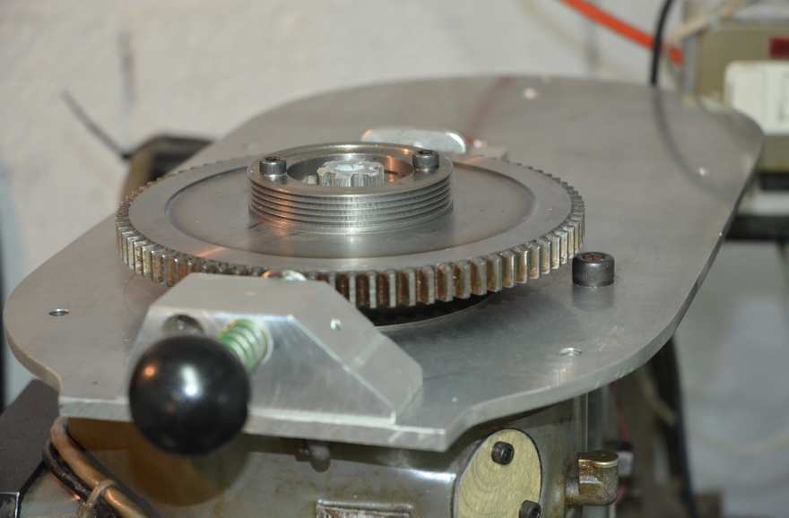
I have close to 100 teeth so I would have a resolution of around 1°.
Currently I have two pickups for a single pulse. One for a cheap tacho and the other for an index pulse. My intention is to add a couple more to pick up on the teeth.
As the spindle speed is close to constant, for a task like this I think that one could get away with some pulse frequency multiplication to fake better resolution.
Attachment 34301 Attachment 34302 Click images for full size.
If I want the polygon to twist 60 deg in .5 inches (the photo) I send it 60/.5=120. Gear tooth sensor are not that expensive - Although I don't t now the availability in france.. \
I used allegro ATS667LSGTN-T
sam
Lathe mode...
https://www.youtube.com/watch?v=P0RP7s-rDsg
Now finally starting to upgrade the encoder.
https://youtu.be/VmWeXS6y-lg
I think it works better....
http://electronicsam.com/images/gree...426_112519.jpg
I think you are right. That is pretty good.Quote:
Originally Posted by skunkworks
I think I get a D for effort...
https://youtu.be/a7CO9gohaXE
http://electronicsam.com/images/gree...428_191604.jpg
Does the material make a difference? Really nice, thank you for posting.
Ralph
Proobably mostly depends on the the tool shape, stiffness and machine rigidity.. (and spindle torque at low rpm)
Quote:
Originally Posted by Ralphxyz
I do actually talk at about 6:30m
https://www.youtube.com/watch?v=PtD9w6lp8n8
I sure love seeing it cut, what motors and drivers do you have with your CNC?
This is a tormach 440 sized mill I got for doing some work. (it was literally tormach's prototype. Thank goodness they didn't go with this supplier..) It had a lot of fit and finish issues.
So the steppers are what would be on the 440 and a leadshine mx3660 runs them. The spindle is a 750w iirc brushless that I am running with a stmbl drive. (open source swiss army knife of servo drives)
https://www.youtube.com/watch?v=n2BGYOcmC4w
Thanks! I have a riser for my 8520 on my todo list. Besides motorized XYZ.
Ralph
Yes - this needed a riser.. I added a good 5". Without it - the nose of the spindle went below the table...
Quote:
Originally Posted by Ralphxyz
some more playing on an emco lathe..
https://youtu.be/wv7mMS5xKks