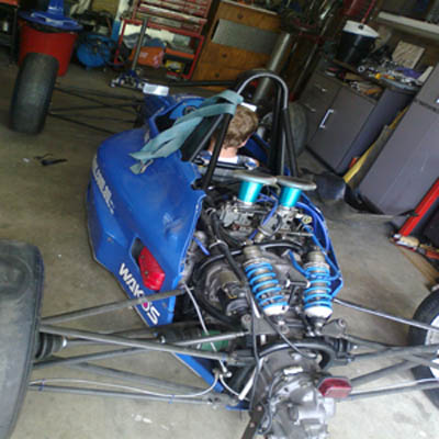
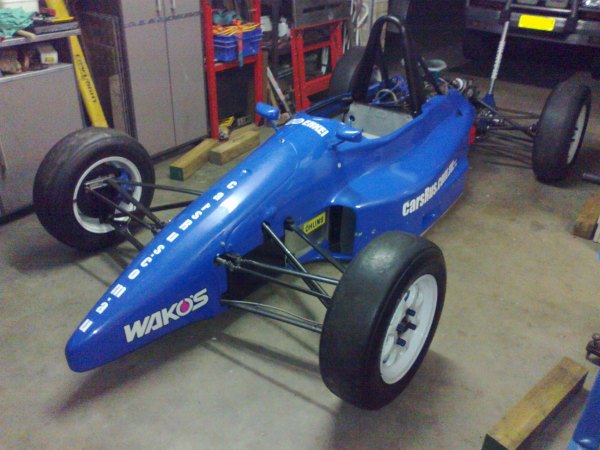
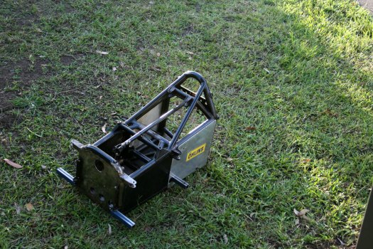
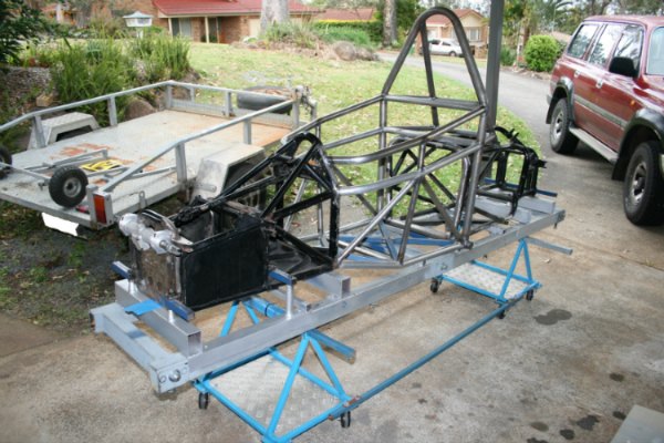
Hi All, I would like to post some pics of my racecar and chassis jig.
Attachment 3471Attachment 3472Attachment 3473Attachment 3474
I will do a more detailed write up of these at a later date but for now I just want to see if I can post the photos.
Printable View
Hi All, I would like to post some pics of my racecar and chassis jig.
Attachment 3471Attachment 3472Attachment 3473Attachment 3474
I will do a more detailed write up of these at a later date but for now I just want to see if I can post the photos.
Looks good. Can't wait to see the rest of the project. I've got some seat time in Formula cars and have always loved open-wheel racing. That said, my current project is an Ultima GTR and I'm looking forward to some track days in that, too!
Ken
Looks fun :rocker:
Cool, Astro! The closest experience I have to open wheel motorsports are karts. Plenty of experience with rally cars though. did you build that chassis jig yourself?
An Ultima would be awesome. Aren't they basically an open wheel car with body panels, ie a little more refined? What engine are you using? Oh, and thanks Ken for the advice on posting, I owe you one: idea:Quote:
Originally Posted by kbalch
Hi DIYer, my closest experience so far has also been in karts, but I've always wanted to build an openwheeler. I used to hillclimb my road car years ago before I got into karts and one thing that's stuck in my mind, was something an old guy told me at a hillclimb one day. "road cars, built for racing are always a compromise, racing cars are built with one purpose in mind, to go fast around a circuit" That comment has always stuck with me and from then on I have wanted to build one. That was about 20yrs ago and I am only now getting around to the build process. Sometimes life gets in the way! Oh and yes I did build the jig, I will do a detailed write up soon.:)
".. open wheel car with body panels…" = as good a description of the car as I've heard. It's essentially an homage to the late '80s & early '90s Le Mans Group C cars. The wishbone/upright arrangement is very reminiscent of an open-wheel setup.Quote:
Originally Posted by Astro
I've got a 700+ HP LS7 sitting on a pallet, waiting its chance to start making noise…
Ken
Cool, Astro. The closest I've come to open wheelers are a McLaren MP4/4 on static display and a Formula Renault racer a friend won a seat in. Interesting cars all. :)
Getting excited about seeing that Ultima rolling, Ken!
Wow, that thing is gonna be a rocketship, do you need NASA's approval for takeoff? :cool:
It takes balls (and a sprinkling of self-confidence) to take on such a big project :bow:
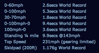
It ought to be fairly quick… :cool: The factory numbers:
Attachment 3498
A big project like this is really just a series of smaller tasks that eventually get assembled into something larger. The airplane I built was far more complex.
Living, as I do, <90 miles from the Kennedy Space Center, I'm already scheming for a way to get the Ultima out on the old SLF (Shuttle Landing Facility) runway…
Ken
Those numbers, Ken, are they for a powertrain similar to yours? Getting to use that old shuttle runway would be a blast! :thumbsup:
The factory numbers were done with a 720 HP SBC. I've got a 712 HP LS7, so it's right in the ballpark. Same transaxle in both cases. Performance should be pretty close…
Ken
Wow, that's all I can say! :thumbsup:
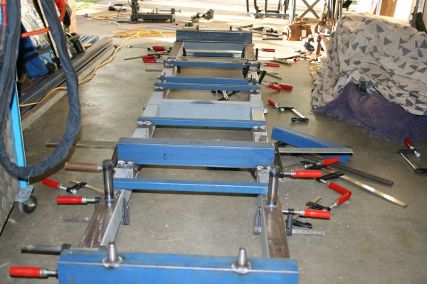
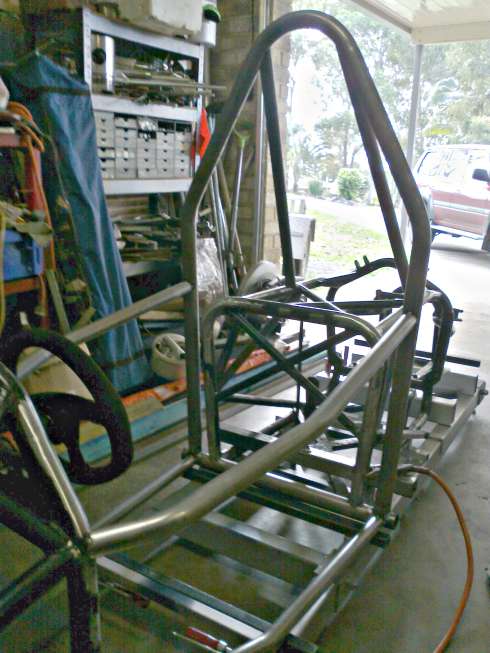
Hi All, I thought I would post some details about the jig I built.
I built the jig because I had to cut my the cockpit out of my chassis to make room for my big ass.
Actually I could fit in the car, but did not have enough room for my elbows to steer the car, so to make it more comfortable, I am lengthening by 100mm and widening by about 130mm. I am building a new roll hoop to be compliant with local regulations and my new cockpit bars will attach to this.
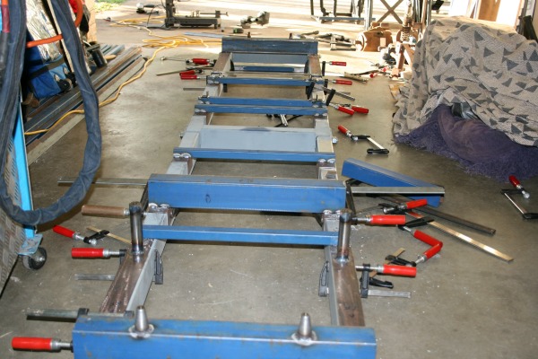
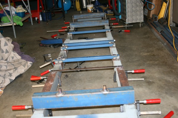
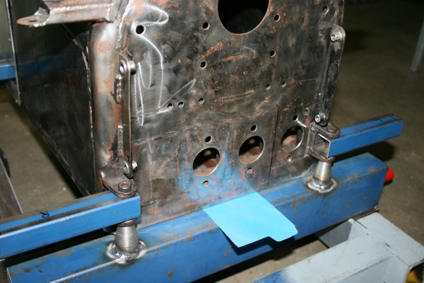
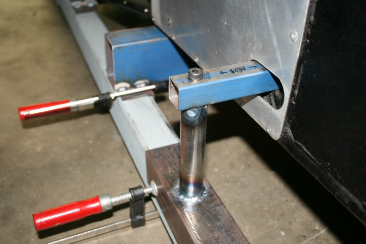
I wanted to maintain the suspension alignment after the car was cut, so I first made the jig rails from 75x50x3 RHS, or 3"x2"x1/8" for the imperialists. These ended up being about 3800mm long. For the three cross braces I used the same size RHS and I welded 50x50x3 angle to the ends of the braces so that they fitted snugly inside of the main rails. I then made intermediate bracing which could be slid along the rails, which would support the chassis. I secured these with screws once they were in final position after the chassis was cut.
Attachment 3589
Attachment 3590
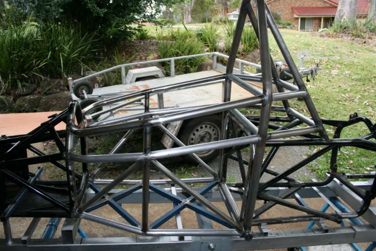
To tie the cross bracing together I drilled the main rails 16mm through the side where the bracing is located and fitted 16mm threaded rod right through both rails, securing each side with a nut.
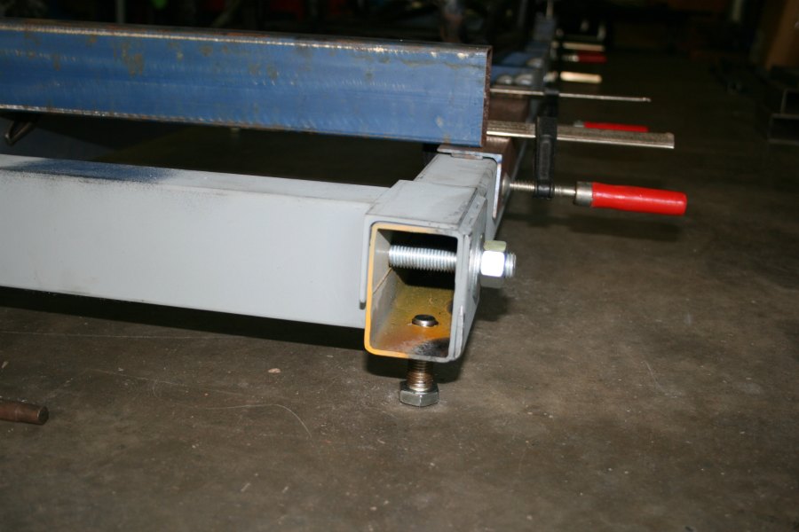
I drilled 16mm holes in four locations along the length of the bottom of the main rails and welded 16mm nuts to them to accommodate levelling feet as my concrete slab is not very level or even.
Attachment 3588
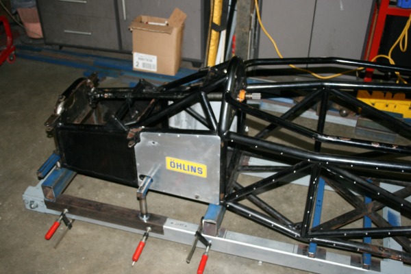
To accommodate the suspension pickup points I made bracing with the 50x50 angle on the outside of the rails and attached some threaded towers which were welded to the front and rear.
Attachment 3591
Attachment 3592
This process took a lot of measuring before I finally committed to cutting the car but I'm sure it was worth it as I can be sure that the car will be straight when it goes back together.
Attachment 3595
Attachment 3593
Attachment 3594
Thanks Astro! I've added your Chassis Jig to our Automotive and Metalworking categories, as well as to your builder page: Astro's Homemade Tools. Your receipt:
<div id="blocks"> <div class="block b1 pngfix"> <div class="bimg"> <div> <a href="http://www.homemadetools.net/chassis-jig-4"><img src="http://www.homemadetools.net/uploads/118292/chassis-jig-4.jpeg" /></a></div> </div> <div class="head pngfix"></div> <div class="left pngfix"></div> <div class="right pngfix"></div> <div class="blockover b1 pngfix"> <div class="title"> <a href="http://www.homemadetools.net/chassis-jig-4">Chassis Jig</a> <span> by <a href="/builder/Astro">Astro</a></span> </div> <div class="tags">tags: <a href="http://www.homemadetools.net/tag/jig">jig</a>, <a href="http://www.homemadetools.net/tag/chassis">chassis</a></div> </div> </div> </div>
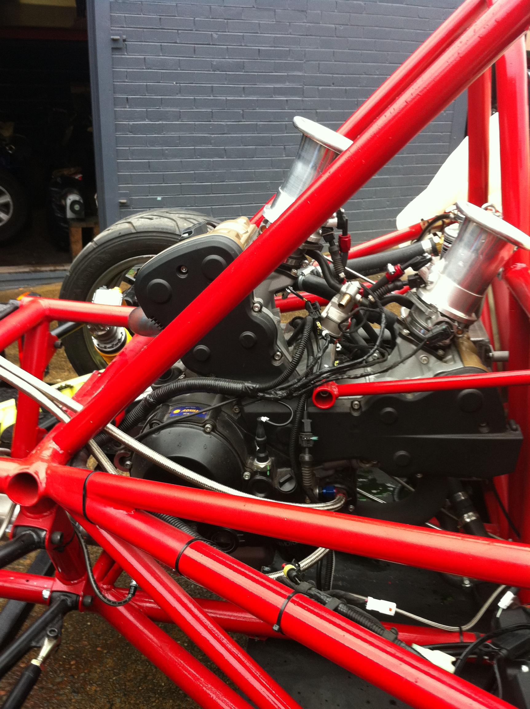
kblach you would like this then the Spartan.
I know all about this nice toy and have a few photo's when I figure out how to post them on this forum most need resizing as they are too big a file size as we did the dyno work setting this Ducati 1198 Engined track car up.
Attachment 3972
https://www.youtube.com/watch?v=wNMlU5ee-Sg
Yep, that Spartan should be a lot of fun with the Ducati 1198 engine providing fantastic performance and soundtrack. Of all my motorcycles over the years, I'll always have a soft spot for the 1200 Multistrada - superbike performance with comfortable, upright seating - what a bike!
Ken
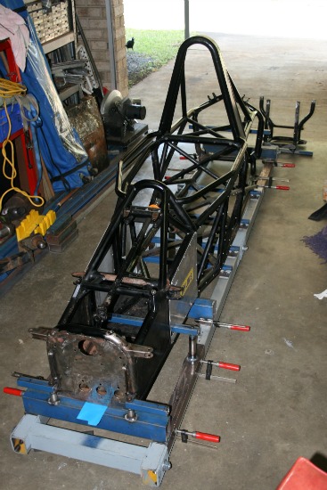
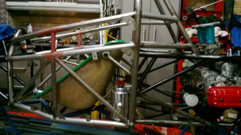
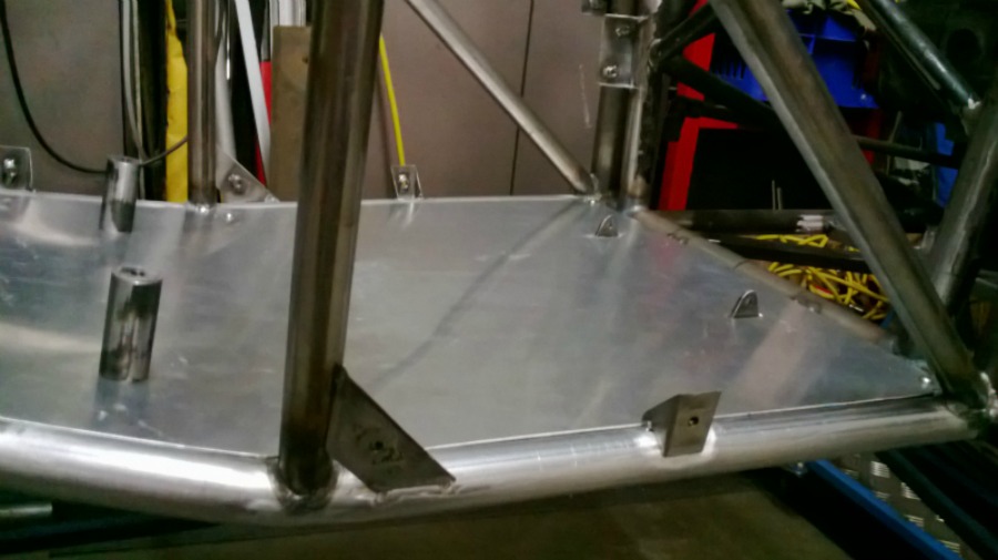
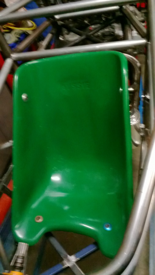
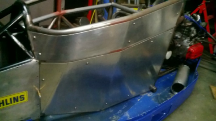
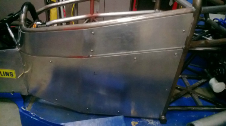
Hi All, it's been along time since I last posted but I thought I might give a bit of an update on the chassis build.
The frame is back in one piece (finally) and appears to be square and straight, although the major pieces have been welded, there is a multitude of brackets and additional mounts to be made. Items I have mounted include, the fiberglass seat, alloy sheet cockpit side panels and floor, battery, fuel tank , fuel pump, gear shift. I have the chassis off the jig currently to fit the engine and gearbox to allow me to fab the exhausts (and anything else I can think of) before I return it to the jig for final welding of all those ancilliary brackets and fixtures.
Attachment 5909Attachment 5910Attachment 5911Attachment 5912Attachment 5913Attachment 5914
Looks great! :thumbsup: Coming along very nicely.
Ken
Looking good, Astro! Appreciate your keeping us updated. :)
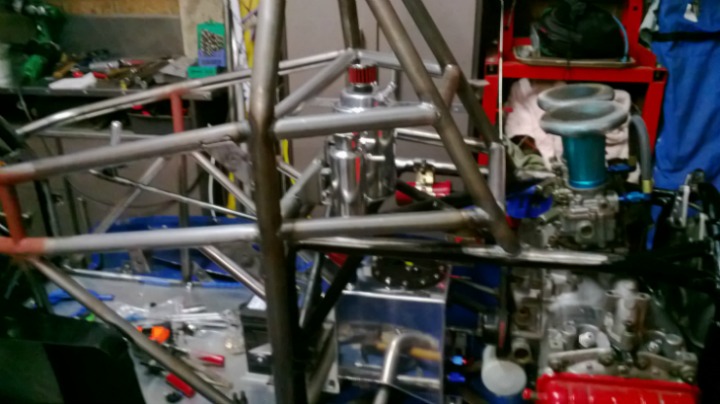
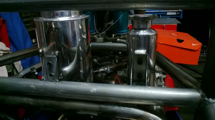
Some more progress on the car. Made new inner body panels and mounts, these really soaked up a lot of time.Attachment 7734Attachment 7735
Fitted an new fuel tank, header tank and oil catch can.
Attachment 7736Attachment 7737
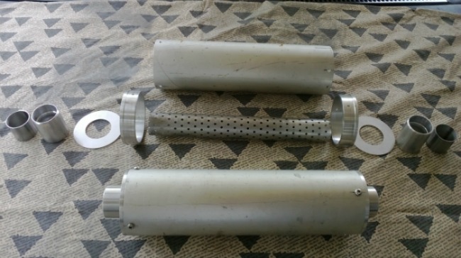
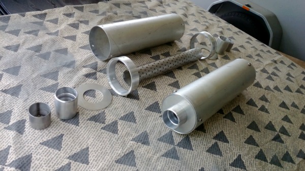
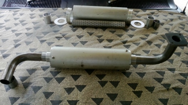
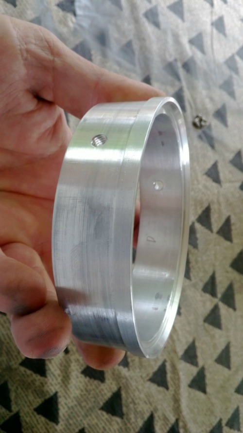
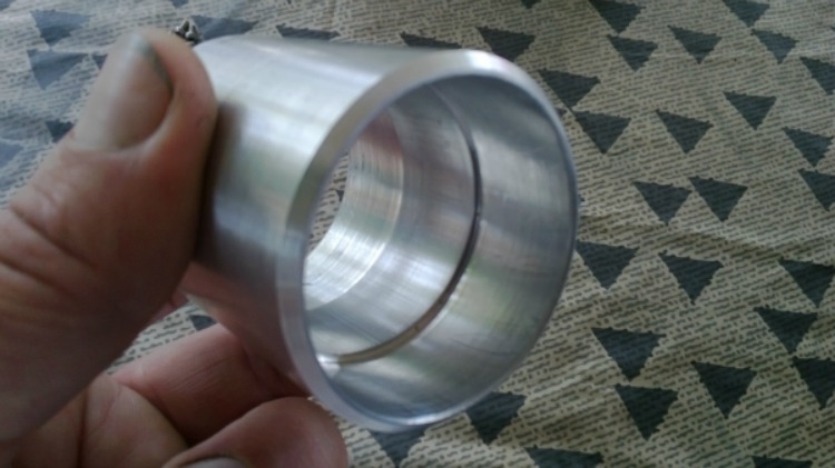
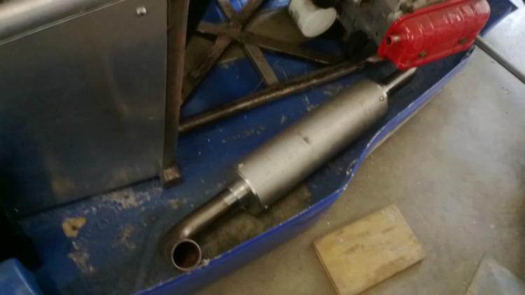
I am making my own mufflers as I could not get commercially available ones to suit what I wanted. The main muffler body is 100mm by 1.5 wall, I had intended to machine the end caps from 1 billet but that was going to become expensive so I machined end cap rings from 100mm x 6mm wall tube, the rings were tapped m6 in 3 positions on each cap to allow me to disassemble to repack the mufflers. and made end plates from 3mm plate. The end cap socket I made from 50mm x 6mm wall, they were bored to fit the perforated tube on one end and an adaptor sleeve on the other end which will be welded to the exhaust tube. are all yet to be welded together. Just hope the sound is OK.
Attachment 7738Attachment 7739Attachment 7740Attachment 7741Attachment 7742Attachment 7743Attachment 7744
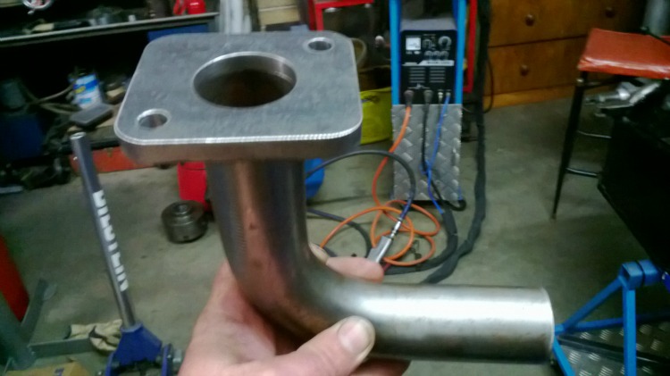
I decided to run the exhausts forward in the body exiting out the side of the undertray, this made the exhausts much easier to make rather than running them through the suspension links and out the back.
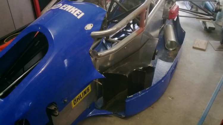
I have cut the original fibreglass bodywork to allow widening and am in the process of fitting all of that together with radiator ducts and new mounts.Attachment 7745
OK, back to the shed for now.
Great progress and excellent work! I'm really looking forward to seeing it running.
Ken
I needed to make new radiator tubes to suit the longer chassis from 1.25inch aluminium tube. It would have been easier to re-create the existing cooling circuit, but this was designed to have the two radiators in series rather than in parallel, and from my research I learned that parallel was the superior configuration. New pipework was made using my homemade tubing bender and bead roller. The thermostat housing located on the inlet manifold was modified to re-position it for a more favourable hose path. Mounts were welded to the chassis to accept 32 mm P clamps to support the radiator pipework. A temperature sensor was incorporated into the top hose run.
A new aluminium dash panel was fabricated to house a mycron3 digital dash unit. Although the car came with adjustable brake bias, the cockpit adjuster was a bit basic. A tiny little knob was used with no detents. A new larger bias adjusting knob assembly was made with detents.
The clutch was actuated by a heavy duty cable which was routed between the rear shocks and anti-roll bars. This installation had caused some interference with the roll bar links so a solution was needed. I could not find a suitable location for the cable which did not cause obstruction of some sort, so a hydraulic conversion was undertaken. This entailed mounting a master cylinder to the front bulkhead, strengthening the bulkhead in this location to cope with the increased load of clutch actuation and finding a suitable slave cylinder to operate the clutch fork. The first couple of tasks were quite easy to accomplish, but obtaining a slave cylinder to mount in a suitable manner became frustrating, to the point where I decided that the only way to make this conversion work, was to manufacture a slave cylinder myself. The difficulty with this installation was that the cylinder had to mount to a plate parallel to the bellhousing, but the clutch fork operated at a compound angle in two planes. I made some mock up cylinders first to check measurements and clearances, then when all was good, I made two cylinders from aluminium. Two, because you can always use a spare.
I have the fiberglass bodywork mostly complete but still some work to go. The original bodywork needed some freehand blending which was helped by the use of polyurethane foam blocks and some flat fiberglass sheet which I laminated. When finished to a final shape this was glassed over and the foam was removed from the inside and glassed on the inside. I could have left the foam in place but polyurethane foam creates a cyanide gas when burnt. Not that I intend burning the thing, but you never know.
The side pod bottom edge was raised by 10mm to allow more support around the dzus fastener holes as the old ones were very close to the edge and cracked easily. Exhaust outlet flanges were fitted to the undertray and will be riveted on. New mounts have been made for the nose hatch which allows access to the shocks and pedal assemblies.
An air box was fabricated in fiberglass, incorporating a flat panel filter to feed the two Hitachi carbs, as originally they were fitted with tall ram tubes and only a stainless steel mesh covering them to keep out the small rocks and insects. As I intend running this car at some less than ideal venues, I figured a filtered engine intake would be the way to go. The mould for this air box came from the local dollar shop in the form of a rectangular plastic tub. I plan to incorporate a couple of shorter ram tubes inside of the air box under the filter. Air inlets will be cut into the front and top of the air box when I finally have it bolted down.
The original head rest was sectioned and raised in height and blended with the surrounding bodywork and air box.
More photos to follow.