Free 186 More Best Homemade Tools eBook:  
Get 2,000+ tool plans, full site access, and more.

User Tag List

Page 15 of 23 FirstFirst 1 2 3 4 5 6 7 8 9 10 11 12 13 14 15 16 17 18 19 20 21 22 23 LastLast
Results 141 to 150 of 227

Thread: Rotary Phase Converter (Create 3-phase power from a single phase source)

  1. #141

    Join Date
    Feb 2017
    Posts
    23
    Thanks
    0
    Thanked 0 Times in 0 Posts
    to old kodger,

    Maybe it would be beneficial to list the motor nameplate ratings or the complete device power ratings that you intend to run with a RPC. Like the name plate data, such as nominal voltage, nominal current, useful information like that. Especially list the nameplate data for the three phase idler you are contemplating using. We already know what your available voltage supply is (240 volts, single phase). If you plan on applying 2 phases of 240 volts that are 180 degrees apart you WILL BE APPLYING 480 volts to a three phase idler motor that you say is rated for 415 volts. The output of the idler motor will be slightly less than 480 volts with no load applied. Do you really want to apply these voltages to your three phase loads that I assume are rated for 415 volts?

    186 More Best Homemade Tools eBook

  2. #142
    Supporting Member
    Join Date
    Feb 2016
    Posts
    123
    Thanks
    22
    Thanked 21 Times in 19 Posts
    Quote Originally Posted by old kodger View Post
    nhengineer,
    I couldn't help myself!

    Junker2,
    It might be a good idea for you to go back and read all the previous posts. this particular part of the discussion is referring to AUSTRALIA, stop thinking America. We have a minimum of 240volt motors, and three phase motors are ALL 415volt (read Paul's post about vector maths) two 240 volt phases 120 degrees out of phase will produce 415 across L1 and L2, jeesh!

    Rob.
    Rob Go easy on the fellow

    2000 Tool Plans

  3. #143
    Supporting Member
    Join Date
    Oct 2016
    Posts
    1,113
    Thanks
    25
    Thanked 345 Times in 242 Posts

    old kodger's Tools
    junker2

    JUNKER2 WROTE "you WILL BE APPLYING 480 volts"

    For the last time.

    No I wont! Star (Y) configuration puts L1, L2, and L3 at the ends of the star with neutral at the point of junction EACH LINE IS PROVIDED WITH, AND RATED AT 240 VOLTS. Vector math changes that to 415.

    Rob.

  4. #144

    Join Date
    Feb 2017
    Posts
    23
    Thanks
    0
    Thanked 0 Times in 0 Posts
    Originally posted by G.Paul
    " Rob Go easy on the fellow"
    Why thank you G. Paul

    To old kodger,

    My vector math tells me if you apply 480 volts to the L1 and L2 terminals (or the L2 and L3 terminals, or the L1 and L3 terminals) of a star
    connected motor you will get 277 volts across the motor winding between the L1 terminal and the "neutral" of the star and 277 volts
    across the motor winding between the L2 terminal and the neutral of the star (480 divided by the square root of 3). Are using some different kind of vector math than I am?
    Last edited by Junker2; Mar 11, 2017 at 12:20 PM. Reason: typo

  5. #145
    Supporting Member
    Join Date
    Oct 2016
    Posts
    1,113
    Thanks
    25
    Thanked 345 Times in 242 Posts

    old kodger's Tools
    junker2,

    It's called "empirical evidence" But you believe what you want to believe, it doesn't change reality.
    I'm sorry if I jumped on you, the reason is because from half a world away, you are trying to tell me that what's on my bench is only a figment of my imagination.

    Rob.

  6. #146

    Join Date
    Feb 2017
    Posts
    23
    Thanks
    0
    Thanked 0 Times in 0 Posts
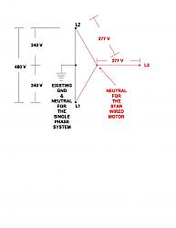
    Here is the vector diagram when you apply 480 volts single phase to the L1 and L2 terminals of a three phase 415 volt star wired motor.

    Rotary Phase Converter (Create 3-phase power from a single phase source)-480-v-applied-415-v-star-motor.jpg


    Please note that you have 277 volts across each motor winding while the idler motor is running.

    It has already been suggested by Frank S that you would need 415 volts.

    "Originally Posted by Frank S.

    To run a RPC (rotary phase converter in Australia, if you are in rule areas you could have what some call 2 ph 480 which would be to hots and neutral. but most areas without 3 ph or the rule areas with 2 ph there is only 1 240v line with a nuetral. to make a RPC run in those places a transformer would be required to make the 415v split phase L1 +N for input then tap at 175-0 240 +415 nominal for output. then connect the 2 output line to the PRC and the cap bank for starting and a module of thyristers for full balanced true sine wave 3p output.
    Here is a commercial site selling their product but the information there will give you an idea of how to go about it
    3 Three Phase Power Converter Australia converts single phase to three phase.
    I think if it were me needing to do this I would buy MR nhengineer's plans then go from there adding what might be needed and contacting him for assistance."

    Your cheapest alternative is to re-wire the 3 phase idler motor and the 3 phase load equipment to accept 240 Volt 3 phase delta. Then you will not need a transformer. There are multiple videos of this scheme in operation on you tube.

    "Originally Posted by old kodger

    Rhengieer,
    I thank you for your effort, but now you see what I mean when I say, in Australia most of the options to date are totally uneconomic, for instance, I need to power a 3 phase mig welder which is name-plated at 10 amps per phase which is about 7.1kw at 230 volts. If a 3hp transformer is likely to cost $450 US that's around $600 AU, and I might need two...$1200 plus freight, and as I mentioned before freight from the US to AU needs the surrender of ones first born, I would not be surprised to find that the freight exceeded the initial cost of the transformers. Also 3hp would woefully inadequate, I need at least 10 amps per phase, for a overload margin, maybe more.
    So at a potential cost in excess of $2400, a second hand 3 phase generator is starting to look a lot more realistic.
    I thank you for all your effort, and indeed to all the other contributors to this thread, but unless I can find a way to control a synchronous motor acting as a generator, I have two options:- buy a generator or attempt to rewire the welder to run on single phase. Incidentally, I'm informed by the manufacturers of the welder, that the configuration internally is actually three separate transformers feeding a bank of full wave bridges, so it could be possible.
    If anyone is interested I'll keep you informed.

    Rob."
    What empiracal evidence are you referring to Rob? Your power calculations make no sense what so ever to me. Is it 10 amps three phase at 415 volts or 10 amps 3 phase at 240 volts and what is the power factor?

    Good luck with your project

    Junker2

  7. #147
    Supporting Member
    Join Date
    Oct 2016
    Posts
    1,113
    Thanks
    25
    Thanked 345 Times in 242 Posts

    old kodger's Tools
    Junker2,
    The reason you can't make it seem to work, is because your circuit schematic is wrong.
    The ground between the two 240 volt "phases" should be connected to the junction point of the star. What you are trying to do is connect the circuit up delta, and you can only do that with a rotating supply (genuine 3 phase 120 degrees displaced), at which point you will find 415 between any two phases.

    The question of "my maths" is one of terminology. All phases in Australia are 240 volt between hot and ground, therefore, 3 phases are 3 lots of 240 volt 120 degrees apart. In the instant of the welder, name plate amps are "10 amps per phase" and since the welder does not require a rotating supply it is in effect a star wound device (each phase 'pulls' 10 amps) giving you 30 amps across all phases. However all three phases after transformation, ultimately feed into a full wave bridge, thereby giving the result of one big transformer producing DC output.
    This could be done with one big transformer but it's not the economic way to go (wire sizes, breakers etc,) so split the load between 3 phases and recombine after transformation to achieve final output.
    At this point however I must desist, because this thread is supposed to be about rotary conversion of single into 3 phase, we are no longer talking about that, so have in effect hyjacked the thread.

    Rob.

  8. #148

    Join Date
    Feb 2017
    Posts
    23
    Thanks
    0
    Thanked 0 Times in 0 Posts
    To Rob AKA: old kodger,

    It is obvious you do not understand 3 phase power systems. The welder does require a three phase "rotating" power supply to function correctly at name plate rated output. The correct power calculation for a three phase system is "volts" times "amps" times "square root of 3" times "power factor". So if the imaginary "welder" nameplate data states 10 amps at 240 volts at three phase it would consume 10 times 240 times 1.73 times some unknown power factor that you can not specify since you have no clue what a "power factor" is. The absolute maximum consumed power for the welder would be 4157 watts. The current does not flow from the 240 volt point of the star to "ground".
    In the 480 volt single phase diagram I uploaded previously, if you connect the single phase ground to the neutral of the 415 volt star wired idler motor the rotary phase converter will NEVER function correctly. In the first place you need to apply a 415 volt single phase voltage. The mechanical placement of the star wound motor windings are 120 degrees apart on the stator of the motor. The neutral of the star wound motor has to "shift" relative to the existing ground of a 415 volt single phase system while the idler motor is rotating. If you hardwire the existing ground to the neutral of the idler motor you are electrically exciting two of the motor magnetic pole pairs with a voltage that is 180 degrees apart.
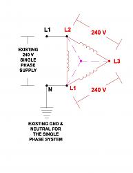
    For your enjoyment I have attached a diagram for a 240 volt delta connected idler motor setup. The magenta colors show the "virtual" neutral point that does not actually physically exist (this was explained by Paul Alciatore assuming you can understand the electromagnetic theory involved).

    Rotary Phase Converter (Create 3-phase power from a single phase source)-240-v-applied-240-v-delta-motor.jpg

    Good Luck
    Junker2

  9. #149
    Supporting Member nhengineer's Avatar
    Join Date
    Aug 2016
    Posts
    187
    Thanks
    10
    Thanked 65 Times in 37 Posts

    nhengineer's Tools
    Quote Originally Posted by Junker2 View Post
    ....So to Mr David Lee AKA nhengineer, you do not have to have a pony motor to start the 3 phase idler motor rotating. You can also use a simple pull rope....
    Yeah *sigh* but I never implied a pull rope would not work. Before running your mouth, Junker2, about something you have not even seen, buy the damn plans and educate yourself..... or are you too cheap?
    Last edited by nhengineer; Mar 15, 2017 at 01:16 PM.

  10. #150
    Supporting Member nhengineer's Avatar
    Join Date
    Aug 2016
    Posts
    187
    Thanks
    10
    Thanked 65 Times in 37 Posts

    nhengineer's Tools
    Quote Originally Posted by old kodger View Post
    junker2

    JUNKER2 WROTE "you WILL BE APPLYING 480 volts"

    For the last time.

    No I wont! Star (Y) configuration puts L1, L2, and L3 at the ends of the star with neutral at the point of junction EACH LINE IS PROVIDED WITH, AND RATED AT 240 VOLTS. Vector math changes that to 415.

    Rob.
    As I may have stated before,

Thread Information

Users Browsing this Thread

There are currently 1 users browsing this thread. (0 members and 1 guests)

Tags for this Thread

Bookmarks

Posting Permissions

  • You may not post new threads
  • You may not post replies
  • You may not post attachments
  • You may not edit your posts
  •