Free 186 More Best Homemade Tools eBook:  
Get 2,000+ tool plans, full site access, and more.

User Tag List

Results 1 to 9 of 9

Thread: Screwing without screwing up.

  1. #1
    Supporting Member tonyfoale's Avatar
    Join Date
    Nov 2016
    Location
    Spain
    Posts
    1,549
    Thanks
    679
    Thanked 2,627 Times in 705 Posts

    tonyfoale's Tools

    Screwing without screwing up.

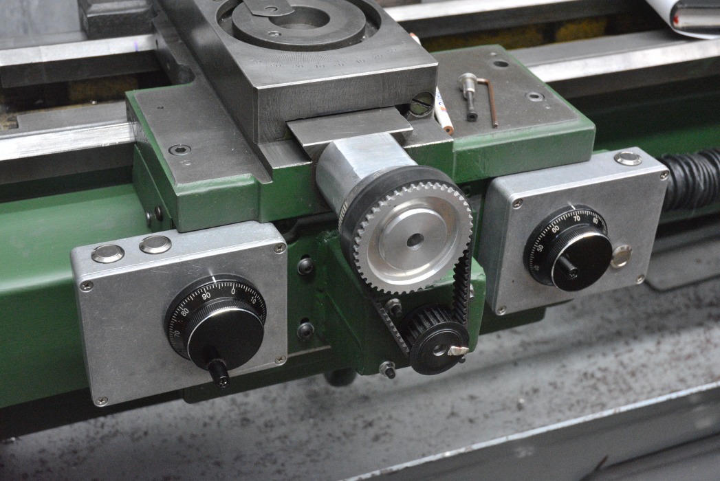
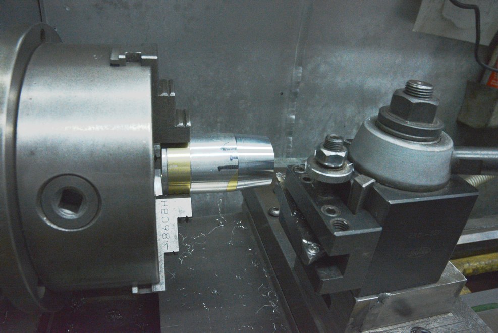
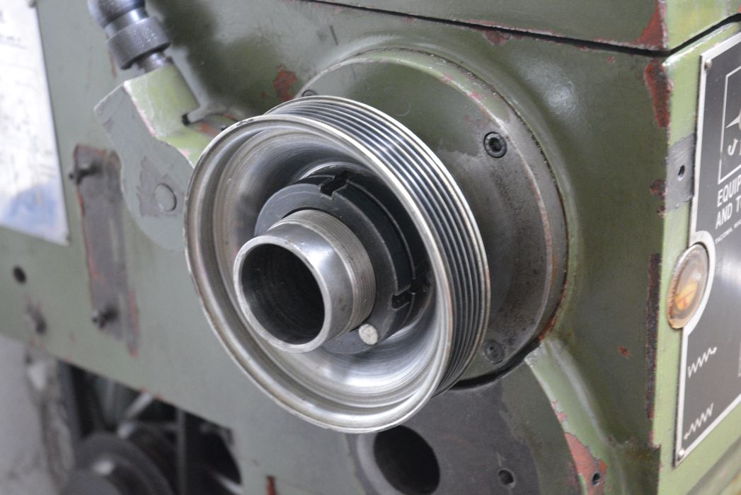
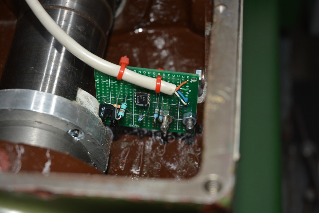
    I have recently been converting my lathe to electronic control.

    Screwing without screwing up.-ballscrew_073.jpg Click for full size

    It is more than an ELS (electronic lead screw) but in some eyes it is less than CNC. I did not want to be hindered by a full CNC - Start the computer, use a wizard, write some G code, use the MDI or make a drawing and pass it through CAM to make a simple item. Not for me.

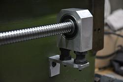
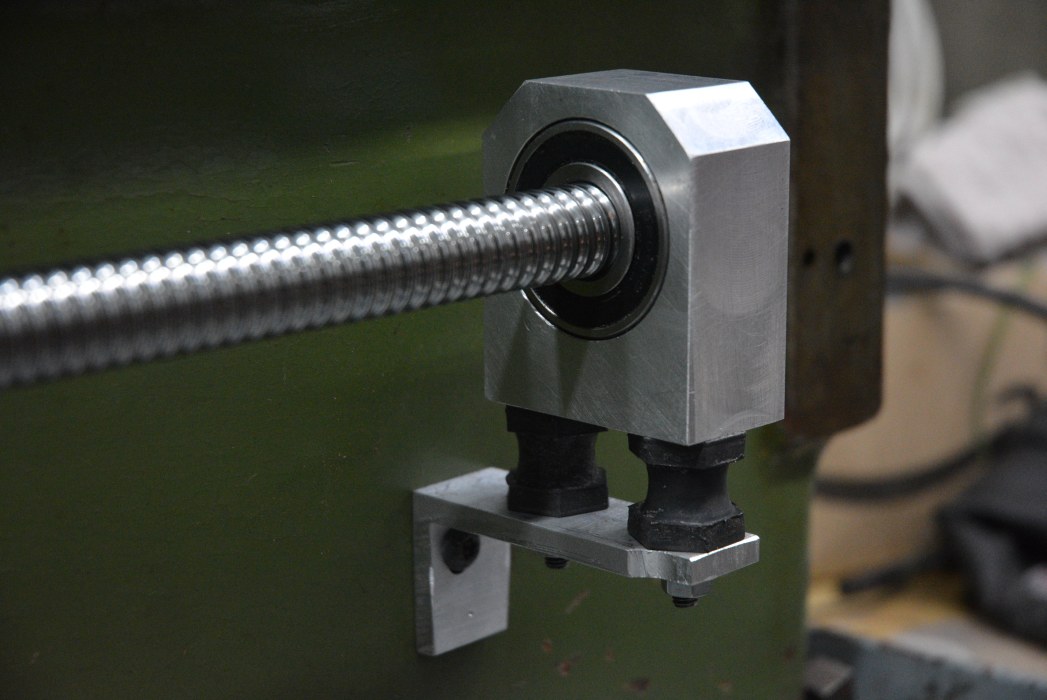
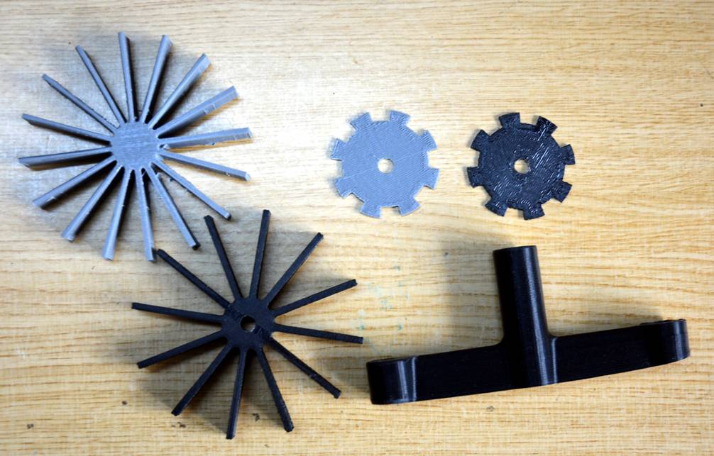
    A while back I made a post about changing the cross slide screw to a ball screw
    Lathe cross slide conversion to a ball screw

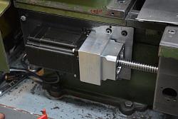
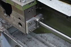
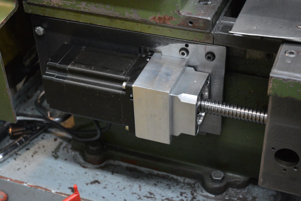
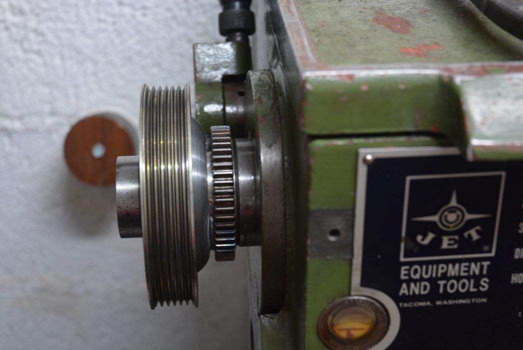
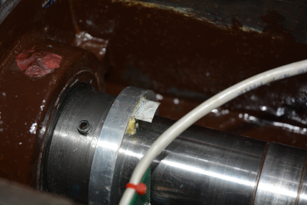
    I liked it so much in use that I decided to do the same for the Z axis. However, putting a hand wheel on the end like the cross slide is impractical to use unless you have a very short lathe. I don't. That meant that it had to be motorised and then it had to be controlled. if the Z axis is motorised and has controls it would be daft to not do the same to the X axis. I call this mission creep.

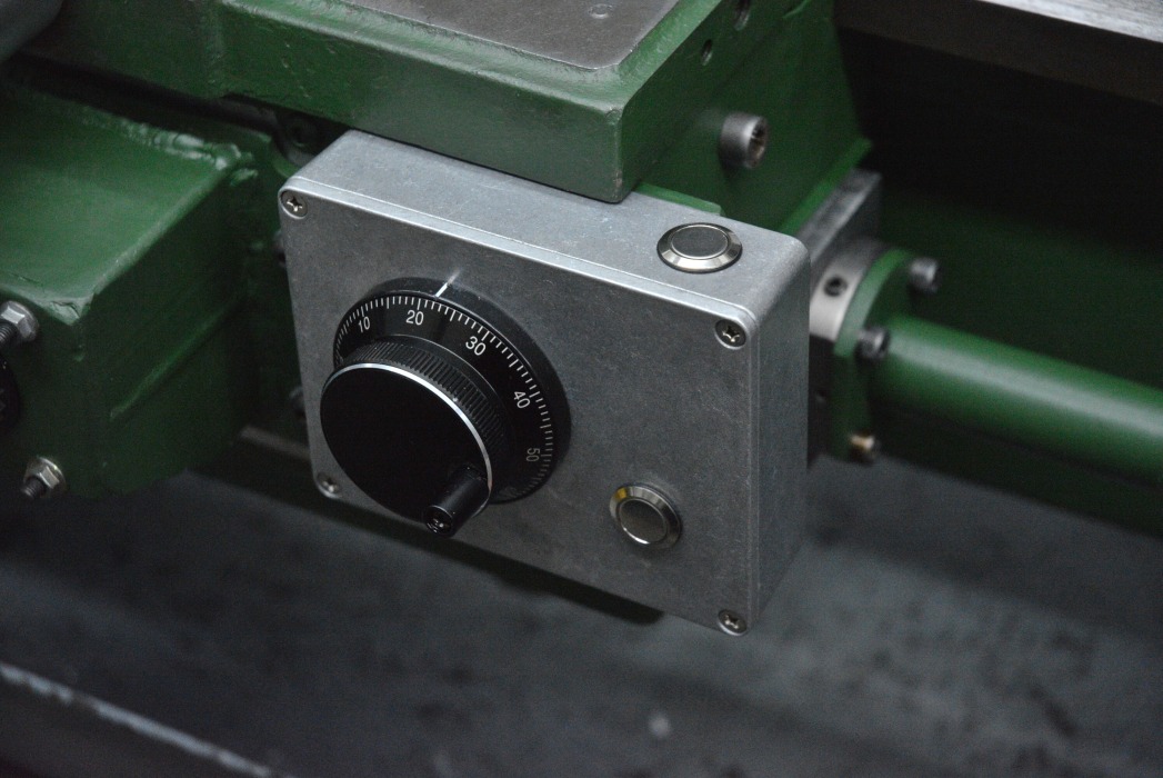
    Now I have all the mechanical stuff needed for a CNC conversion but I did not want a full CNC. However, it seemed like it would be simple enough to use a microcontroller and a few buttons to automate a few standard operations to a CNC level without the setup hassles.

    Screwing without screwing up.-ballscrew_041.jpg Screwing without screwing up.-ballscrew_042.jpg

    Screwing without screwing up.-ballscrew_050.jpg Screwing without screwing up.-ballscrew_071.jpg

    The above is just the intro to what this post is about. I shall be making a video series showing details of all aspects of the conversion but you will have to wait for that.

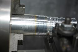
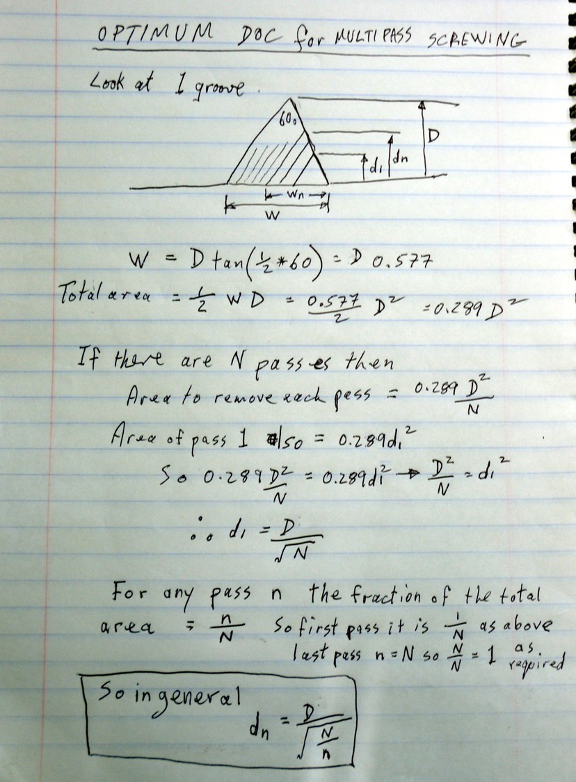
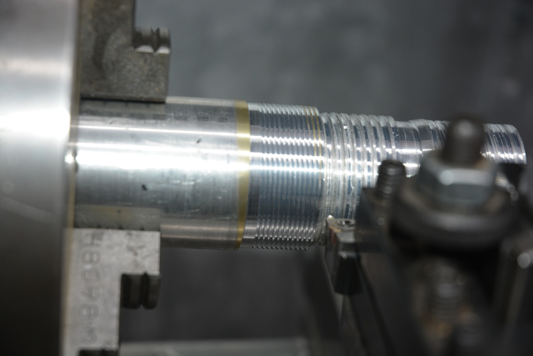
    Multipass screw cutting was incorporated into my dedicated software to control the ESP32 micro. Initially for testing I used the same DOC (depth of cut) for each pass. Anyone who has done lathe screw cutting knows that will result in very little metal removal on the first passes and excess removal on the last passes. So last night i sat down and worked out what DOC each pass needed, to ensure the same amount of material was removed on each pass. Obviously the first pass needs more DOC than the final cut. Here is the derivation, I will point out that for simplicity it is based on the assumption that the total thread depth is small compared to the workpiece diam. Here is the derivation that I came up with;

    Screwing without screwing up.-ballscrew_095.jpg

    I programmed this into my system and did some tests. For a given thread depth and number of passes the even amount of metal removal per pass gave a smoother lathe operation and the final finish was better. The better finish is due to the smaller DOC on the last pass. I made a spread sheet which allows a selection of passes and thread depth and which outputs the DOC for each pass, this is applicable to manual lathe screw cutting and is the main purpose of this post. If all went well the spreadsheet should be attached. just enter the thread depth (in any units) that you want and the sheet will calculate the optimum DOC (in your input units) for each pass for total number of passes from 4 to 9.

    To see the effect of using different DOCs for each pass let's use 6 passes on a thread depth of 1. Refer to the spreadsheet.
    If we used the same DOC for all passes that would have to be 1/6 = 0.16666. using the spreadsheet we see that the optimum would be 0.408 for the first pass but only 0.087 for the final pass. The final pass would have approximately 1/2 of what it be with constant DOC for all passes. The first pass would cut more than before with a depth of 0.408.

    Screwing without screwing up.-ballscrew_089.jpg Screwing without screwing up.-taper.jpg just testing.

    Keep watching there is a lot more to come.
    Attached Files Attached Files

    186 More Best Homemade Tools eBook

  2. The Following 14 Users Say Thank You to tonyfoale For This Useful Post:

    dagrizz (Jun 7, 2021), DIYSwede (Jun 7, 2021), freddo4 (Jun 7, 2021), Home-PC (Jun 7, 2021), JDrouin (Jun 11, 2021), Jon (Jun 10, 2021), NortonDommi (Jun 5, 2021), nova_robotics (Jun 7, 2021), Ralphxyz (Aug 5, 2022), rarmintrout (Jun 10, 2021), rayh__ (Jun 7, 2021), Saltfever (Jun 12, 2021), Toolmaker51 (Feb 16, 2022), uv8452 (Aug 7, 2021)

  3. #2
    Supporting Member NortonDommi's Avatar
    Join Date
    Jul 2014
    Location
    North Island, New Zealand.
    Posts
    990
    Thanks
    1,800
    Thanked 524 Times in 315 Posts

    NortonDommi's Tools
    Thank you for that helpful spreadsheet Tony, much appreciated.

    2000 Tool Plans

  4. #3
    Supporting Member metric_taper's Avatar
    Join Date
    Mar 2017
    Location
    Marion, Iowa
    Posts
    585
    Thanks
    227
    Thanked 256 Times in 153 Posts

    metric_taper's Tools
    I interested if the video shows how you attached a spindle encoder so you can keep the thread timing. I'm hung up on putting an encoder on my big lathe (it has a 100mm OD spindle shaft, so I'm thinking a timing pulley with belt to the encoder shaft). I want to see if I can make a software program that uses an encoder on the feed screw as well, with the intent of enabling metric threads, where I can disengage the half nut, and get a timing signal from a LCD screen for when to engage again. It gets tiresome to reverse it back to where the carriage was, for all these threading passes. My lathe has both Imperial and Metric threading gears with just the flip of one lever. But the feed screw is Imperial. Which is odd with European style metric headstock taper (and delivered to the USA).

  5. #4
    Supporting Member dagrizz's Avatar
    Join Date
    Nov 2019
    Posts
    22
    Thanks
    9
    Thanked 10 Times in 6 Posts
    Now that'll be useful even without electronic controls! Danke!

  6. #5
    Supporting Member DIYSwede's Avatar
    Join Date
    May 2019
    Location
    Stockholm, Sweden...
    Posts
    634
    Thanks
    415
    Thanked 799 Times in 319 Posts

    DIYSwede's Tools
    Thanks Tony - yet another brilliant aid, both the spreadsheet and its derivation!

    This is one of these machining problems I've "just haven't gotten myself into yet",
    just lessening the repeated DOCs on a somewhat intuitive "hunch"
    (which with 20-20 hindsight was way off - took too big a bite in the last passes).

    Following your derivation was to me a spiritual experience - but then I'm just a cheapskate!

    Ta

    Johan

  7. #6
    Supporting Member tonyfoale's Avatar
    Join Date
    Nov 2016
    Location
    Spain
    Posts
    1,549
    Thanks
    679
    Thanked 2,627 Times in 705 Posts

    tonyfoale's Tools
    Quote Originally Posted by metric_taper View Post
    I interested if the video shows how you attached a spindle encoder so you can keep the thread timing. I'm hung up on putting an encoder on my big lathe (it has a 100mm OD spindle shaft, so I'm thinking a timing pulley with belt to the encoder shaft). I want to see if I can make a software program that uses an encoder on the feed screw as well, with the intent of enabling metric threads, where I can disengage the half nut, and get a timing signal from a LCD screen for when to engage again. It gets tiresome to reverse it back to where the carriage was, for all these threading passes. My lathe has both Imperial and Metric threading gears with just the flip of one lever. But the feed screw is Imperial. Which is odd with European style metric headstock taper (and delivered to the USA).
    If you look at the pdf referenced in
    Improving a lathe spindle head.
    you will see how I fitted a magnetic pickup inside the head of the lathe for a cheap tacho, the type that many on this forum use. Of course that is not a solution for everyone because it is rare to have an empty headstock.

    This pickup only gives 1 pulse per spindle revolution and the usual reaction is "that is not enough" but it is what the tacho works with. I did an error study using different number of pulses/rev. and concluded that 40 would be a good number. My plan was to 3D print a notched wheel and sandwich it behind the drive pulley.

    Screwing without screwing up.-swirl02.jpg Screwing without screwing up.-tupperware03.jpg Click for full size.

    These pix show the notched wheel to get RPM and direction for a swirl meter on my flow bench. For the lathe I was planning a much larger version with 40 teeth and a large centre hole, which would fit over the rear of the spindle and clamped behind the pulley as shown here. Then I would use an optical sensor like the one in the above pic. to get the signal pulses which I would pass through a comparator to sharpen the pulses.

    Screwing without screwing up.-lathegbh016.jpg Screwing without screwing up.-lathegbh017.jpg

    The Mach3 CNC software requires only a single pulse/rev for screw cutting, other systems use precision rotary encoders with 1000s of pulses/rev.
    When I analysed what you will do with the pulses I concluded that there was no point to having a very large number. The purpose is to get the time duration between pulses. A single pulse gives the duration of a single revolution, multiple pulses just chops this up into smaller periods. Using single pulse only allows you to calculate the average speed over one revolution but there are several factors which cause the speed to vary over a revolution, such as eccentricity in the spindle and motor pulleys, lack of roundness in the pulleys, lack of homogeneity in the belt/s, beating between motor and spindle, the list is long. Multiple pulses per rev allow the speed variation over a revolution to be accounted for in the calculation of the required carriage feed. The questions are; Is the speed variation over one rev significant? If so, then how many pulses do we need to smooth it out.

    Simple turning or facing would be quite tolerant of spindle speed over a revolution but screw cutting was the critical task. Mach3 were happy with one pulse/rev. As I already had the speed sensor on the lathe I thought that I would see just how good a job could be done with it. The first test threads were by no means excellent but the variation seemed to be from rev to rev not over a single rev. Examination of the pulses from the magnetic pickup showed that it was not firing in exactly the same spindle position from rev to rev. Good enough for a tacho but not for this job. I have noticed this type of variation in hall effect engine ignition systems so it was not a surprise. To get precise spindle location I added a short vane to the rotor on the spindle and made an optical pickup to fit where the magnetic one did.

    Screwing without screwing up.-ballscrew_086.jpg Screwing without screwing up.-ballscrew_084.jpg

    This gave very accurate info about the spindle position once per rev. The threads cut with this were excellent, particularly when I built the optimised depth of cut into the software. I see no reason now to continue with the original plan of the notched plate with multiple slots. I have no need to measure direction of rotation, because that is set by a switch. Otherwise it is only a question of having two optical pickups instead of one.

    There are stacks of videos on the net showing the mounting and belt driving of off the shelf optical encoders if you want to continue down that path. On youtube channel Clough42 there is a long running series on a electronic lead screw conversion which I think shows the encoder mounting.

    I think that a lot of the benefit of my system is due to the precision of the ball screws in place of the original ACME thread and half nuts. I suspect that the limitations of the stock screws/nut exceed the limitations of a single pulse/rev.

    I will go into all this stuff and more in the planned videos. I have filmed a lot and it is a big project to describe so it will take a few videos to do that. I will make a quick intro video soon showing screw cutting.

    Oh BTW. One way to get closer to constant spindle speed over a revolution is to run the spindle fast and let inertia help. Because the electronics are in control I can run much faster than you would dare by hand. My testing has all been above 1000 rpm.

  8. The Following 5 Users Say Thank You to tonyfoale For This Useful Post:

    freddo4 (Aug 1, 2022), Jon (Jun 10, 2021), metric_taper (Jun 8, 2021), rarmintrout (Jun 10, 2021), Saltfever (Jun 12, 2021)

  9. #7
    Supporting Member tonyfoale's Avatar
    Join Date
    Nov 2016
    Location
    Spain
    Posts
    1,549
    Thanks
    679
    Thanked 2,627 Times in 705 Posts

    tonyfoale's Tools
    I forgot to mention that I treat the feeds for screw cutting in the same manner as for turning. So i might set the feed/rev at 0.05 or 0.1 mm/rev for turning. (I can set that in steps of 0.01mm/rev) and say 1 to 5mm/rev for screw cutting. There is no difference in method between metric and imperial. e.g. if I want a 26tpi thread, that is a feed of 1/26 = 0.0385"/rev or 0.98mm/rev. So I would set a feed of 0.98mm/rev.
    The only difference between normal turning and screwing is that in the screwing mode as the depth of cut is increased on the X axis I have it programmed to advance the Z axis in accordance with the thread angle. I only envisage using 60 deg threads and so the Z advance is tan(30) or 0.577 times the X advance. Of course any thread angle could be programmed in but that would need an additional operator input and I like simplicity. I am also running out of pins on the ESP32 micro.

  10. #8
    Supporting Member tonyfoale's Avatar
    Join Date
    Nov 2016
    Location
    Spain
    Posts
    1,549
    Thanks
    679
    Thanked 2,627 Times in 705 Posts

    tonyfoale's Tools
    Here is a pic of the pulses from the optical pickup. The camera speed caught more than one pass, the lateral displacement of the two pulses is due to operator camera shake not variation in the timing point.

    Screwing without screwing up.-ballscrew_083.jpg

  11. #9
    Content Editor
    Supporting Member
    DIYer's Avatar
    Join Date
    Aug 2013
    Posts
    3,056
    Thanks
    772
    Thanked 1,850 Times in 1,652 Posts


    Thanks tonyfoale! We've added your Screw Cutting DOC Spreadshet to our Machining category,
    as well as to your builder page: tonyfoale's Homemade Tools. Your receipt:


    186 More Best Homemade Tools eBook

Thread Information

Users Browsing this Thread

There are currently 1 users browsing this thread. (0 members and 1 guests)

Tags for this Thread

Bookmarks

Posting Permissions

  • You may not post new threads
  • You may not post replies
  • You may not post attachments
  • You may not edit your posts
  •