
 LinkBack URL
 About LinkBacks


If you look at the pdf referenced inOriginally Posted by metric_taper

Improving a lathe spindle head.
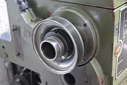
you will see how I fitted a magnetic pickup inside the head of the lathe for a cheap tacho, the type that many on this forum use. Of course that is not a solution for everyone because it is rare to have an empty headstock.
This pickup only gives 1 pulse per spindle revolution and the usual reaction is "that is not enough" but it is what the tacho works with. I did an error study using different number of pulses/rev. and concluded that 40 would be a good number. My plan was to 3D print a notched wheel and sandwich it behind the drive pulley.
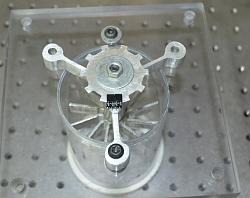
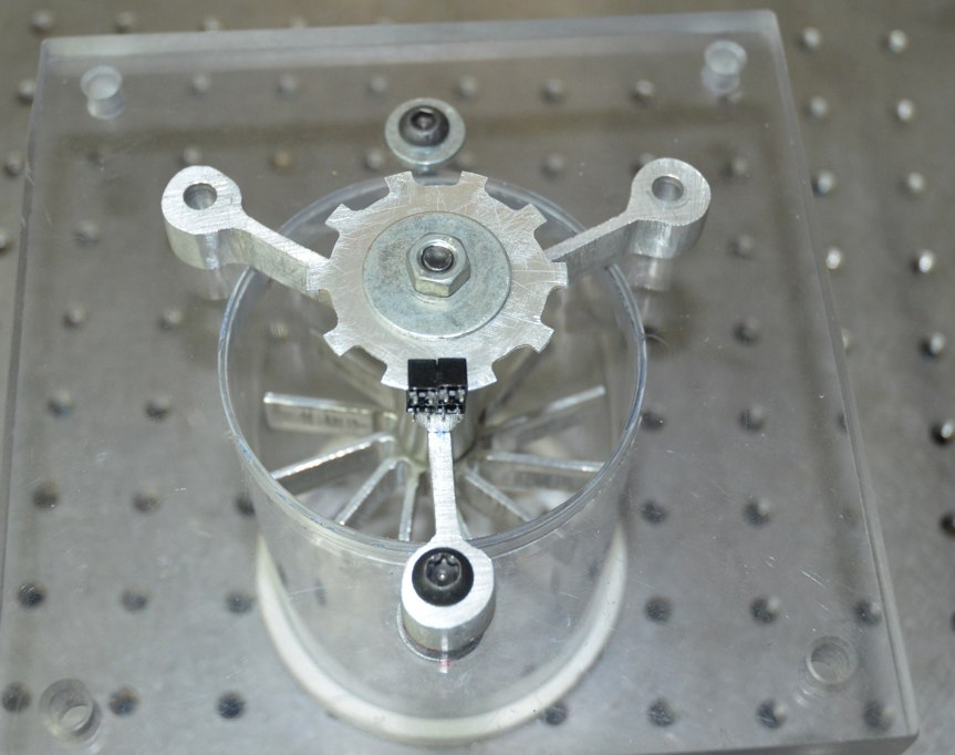
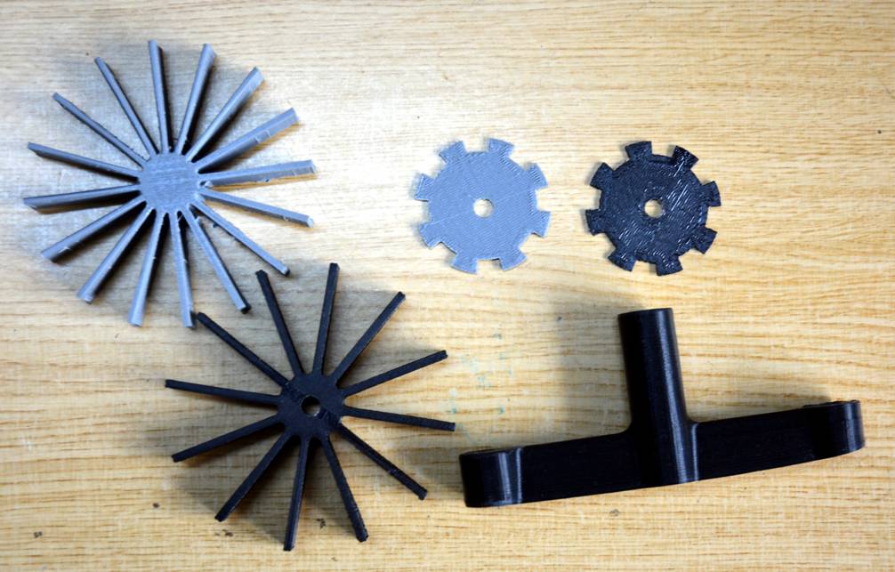
Click for full size.
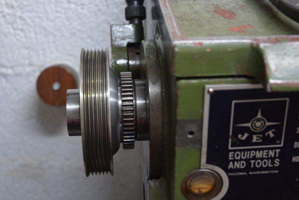
These pix show the notched wheel to get RPM and direction for a swirl meter on my flow bench. For the lathe I was planning a much larger version with 40 teeth and a large centre hole, which would fit over the rear of the spindle and clamped behind the pulley as shown here. Then I would use an optical sensor like the one in the above pic. to get the signal pulses which I would pass through a comparator to sharpen the pulses.
The Mach3 CNC software requires only a single pulse/rev for screw cutting, other systems use precision rotary encoders with 1000s of pulses/rev.
When I analysed what you will do with the pulses I concluded that there was no point to having a very large number. The purpose is to get the time duration between pulses. A single pulse gives the duration of a single revolution, multiple pulses just chops this up into smaller periods. Using single pulse only allows you to calculate the average speed over one revolution but there are several factors which cause the speed to vary over a revolution, such as eccentricity in the spindle and motor pulleys, lack of roundness in the pulleys, lack of homogeneity in the belt/s, beating between motor and spindle, the list is long. Multiple pulses per rev allow the speed variation over a revolution to be accounted for in the calculation of the required carriage feed. The questions are; Is the speed variation over one rev significant? If so, then how many pulses do we need to smooth it out.
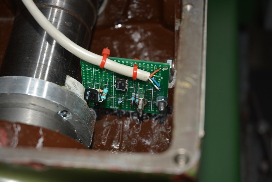
Simple turning or facing would be quite tolerant of spindle speed over a revolution but screw cutting was the critical task. Mach3 were happy with one pulse/rev. As I already had the speed sensor on the lathe I thought that I would see just how good a job could be done with it. The first test threads were by no means excellent but the variation seemed to be from rev to rev not over a single rev. Examination of the pulses from the magnetic pickup showed that it was not firing in exactly the same spindle position from rev to rev. Good enough for a tacho but not for this job. I have noticed this type of variation in hall effect engine ignition systems so it was not a surprise. To get precise spindle location I added a short vane to the rotor on the spindle and made an optical pickup to fit where the magnetic one did.
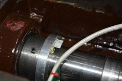
This gave very accurate info about the spindle position once per rev. The threads cut with this were excellent, particularly when I built the optimised depth of cut into the software. I see no reason now to continue with the original plan of the notched plate with multiple slots. I have no need to measure direction of rotation, because that is set by a switch. Otherwise it is only a question of having two optical pickups instead of one.
There are stacks of videos on the net showing the mounting and belt driving of off the shelf optical encoders if you want to continue down that path. On youtube channel Clough42 there is a long running series on a electronic lead screw conversion which I think shows the encoder mounting.
I think that a lot of the benefit of my system is due to the precision of the ball screws in place of the original ACME thread and half nuts. I suspect that the limitations of the stock screws/nut exceed the limitations of a single pulse/rev.
I will go into all this stuff and more in the planned videos. I have filmed a lot and it is a big project to describe so it will take a few videos to do that. I will make a quick intro video soon showing screw cutting.
Oh BTW. One way to get closer to constant spindle speed over a revolution is to run the spindle fast and let inertia help. Because the electronics are in control I can run much faster than you would dare by hand. My testing has all been above 1000 rpm.


 Reply With Quote

Bookmarks