-
Dan Neil won the pulitzer price for criticism in 2004. Was a highly opinionated critic who surely was never invited to any antique, vintage, classic, off road, hot rod, o rany other car show where real car guys congregate. there is not 1 car in his list of 50 that I wouldn't mind owning. Many of the ones he cut to the bone have sold at various auctions for as much as 50 to a 100 times their original purchase price. Even the cars he mentioned in the later years with the too small engines have a collectors appeal to them
-
Unable to locate where I posted information on HMT.net; leading readers to acquire US Navy manuals.
A favorite reference; still the 'Machinery Repairman' 3 & 2, (and) 1 & C. Those cover broad scope of topics from hand tools to administration, same progression of responsibilities as entry level Petty Officers to Chief. Some question their abilities; it isn't generally due to lack of facilities, that's for sure. Being connected with 9 different installations, proved it each time.
Well today, I'm looking for solutions to replicate the foot print of an [my] immense horizontal 4B JigMil. Roughly 15' across, and 10' deep, with 19 leveling screw holes in a not-rectangular foot print. It's time to layout floor cuts, to excavate 8" floor for the 4' foundation required to perform best. While pad will be rectangular, placing the bolts [or anchor holes] will be a challenge. Has to be correct, enabling riggers place machine as intended. It may be more effective to drill deep and epoxy long altered J-bolts. Nothing turns up, even close. Society of the internet isn't well geared for terminology of workmen.
I hate the internet...logical search terms primarily locate advertising instead of directed content; quotes be damned.
BUT did find the US Army equivalent to the Navy manual, they aren't quite clones, and a good thing. I recommend dedicating permanent storage of the address and 300+ PDF pages; thumb, non rewrite disk or print on substantial paper stock for a binder.
It's at http://www.apd.army.mil/epubs/DR_pub...eb/tc9_524.pdf
TC 9-524 FUNDAMENTALS OF MACHINE TOOLS
OCTOBER 1996
HEADQUARTERS, DEPARTMENT OF THE ARMY
DISTRIBUTION RESTRICTION: Approved for public release; distribution is unlimited.
I sure do enjoy the internet...always a better reward in wandering than searching. My settings pull 100 returns per page. Costs same either way, right?
-
Which model Devlieg 4b do you have 4b-96x60 , 4b-120x60 4b -132x64, ETC.
-
My little ol' 4B-48.
And 48" horizontal ro-tab, 30" vertical ro-tab, 15" tilting ro-tab "E" table, pair of 2 piece uprights, end measuring rods, and 50 taper holders in a tooling cart. A lot of boring cartridges, facemills...all in their own zip code in the building, lol.
-
Does it look like this one?
https://youtu.be/7RfUEkz41_4
-
YOu are correct about the horrible lack of easy access to technical drawings on the web. Most all of the info is there somewhere you just have to get by all of the auto fill search bots and ads I used to have a URL that lead me to every military TM that had ever been published. Any machine which was ever in the DOD inventory has a NSN if that number is known then finding the TM's was a cinch. But first having to search SN's models and build dates can be exasperating. Since the creation of the Alibaba thing it has gotten tougher and tougher to get around their over publicized BS
So far this is what I found
Spindle Diameter 4"
W Axis Travel Spindle Travel (In/Out): 24"
X Axis Travel - Cross Travel: 60"
Y Axis Travel - Vertical Travel: 48"
Z Axis Travel - Table Travel (In/Out): 20"
Spindle Motor: 10 HP
Spindle Speeds: 20 - 1800 RPM
Spindle Taper: #50
Table Size: 60" x 48"
Machine Weight: 30,000 lbs
At this page but no foot print yet
http://2spade.com/DeVlieg4B.html
-
I have a manual for 3B model, a bit smaller, but operation is similar. They aren't identical in layout; no footprint there either. Made bookmarks that cover related info, including youtubes like that above.
Thought of making blind transfer punches to mark metal strips, holders for laser rifle/ scope aligner and project on a sheet, a pointed rod with a bubble post level, slotted bars and sliding plugs where there are overhangs...probably wind up using a little of each.
Occurs to me, to take a series of good overlapping pictures; depicting the various positions to analyze offsite.
-
OK here is what I have done when confronted with the need to millwright in a machine for which there was no layout prints
First I would lay out a large square grid around the machine then index the perimeter just like the grid of a map by first marking off smaller grid lines usually in 10 cm increments I try to metrics for this because everything is divisible by 10 this type of a numbering system never fails being left handed my zero point is always lower left this way standing at 1 corner my numbers always get larger going away from me and to the right. or as I term it to the north and to the east. Using 2 long straight edges a framing square a machinist square I can a pair of calipers and round pegs and sometimes a couple o f1 23 blocks or a 90° jig block that exactly fit the holes I can map out on a graph paper where every hole is on the machine that can be reached around its base. For any other holes or if there is electrical or plumbing lines hidden inside or behind other obstructions I have to create datum points which I can translate to my paper graph.
Hope this helps and that I have not completely confused you by leaving out something.
You may literally have to build a square framework out of some stable materials the same height of the top of the base to be able to get a perfect grid it is very important that if the machine is sitting unlevel or currently on a skid for best results the layout grid should be on the same plane as the top of the base or the bottom of the base if there are varying thicknesses to it
-
time spent now solves problems before they happen
-
1 Attachment(s)
Good example of what we formerly knew as "outside the box" thinking process.
So focused on foot print and individual holes, hadn't occurred to think of them more as a pattern with an external datum, and positions within a grid...Exactly as a cartographer might locate features, or navigation from place to place.
Lets forget I spent years doing the latter!
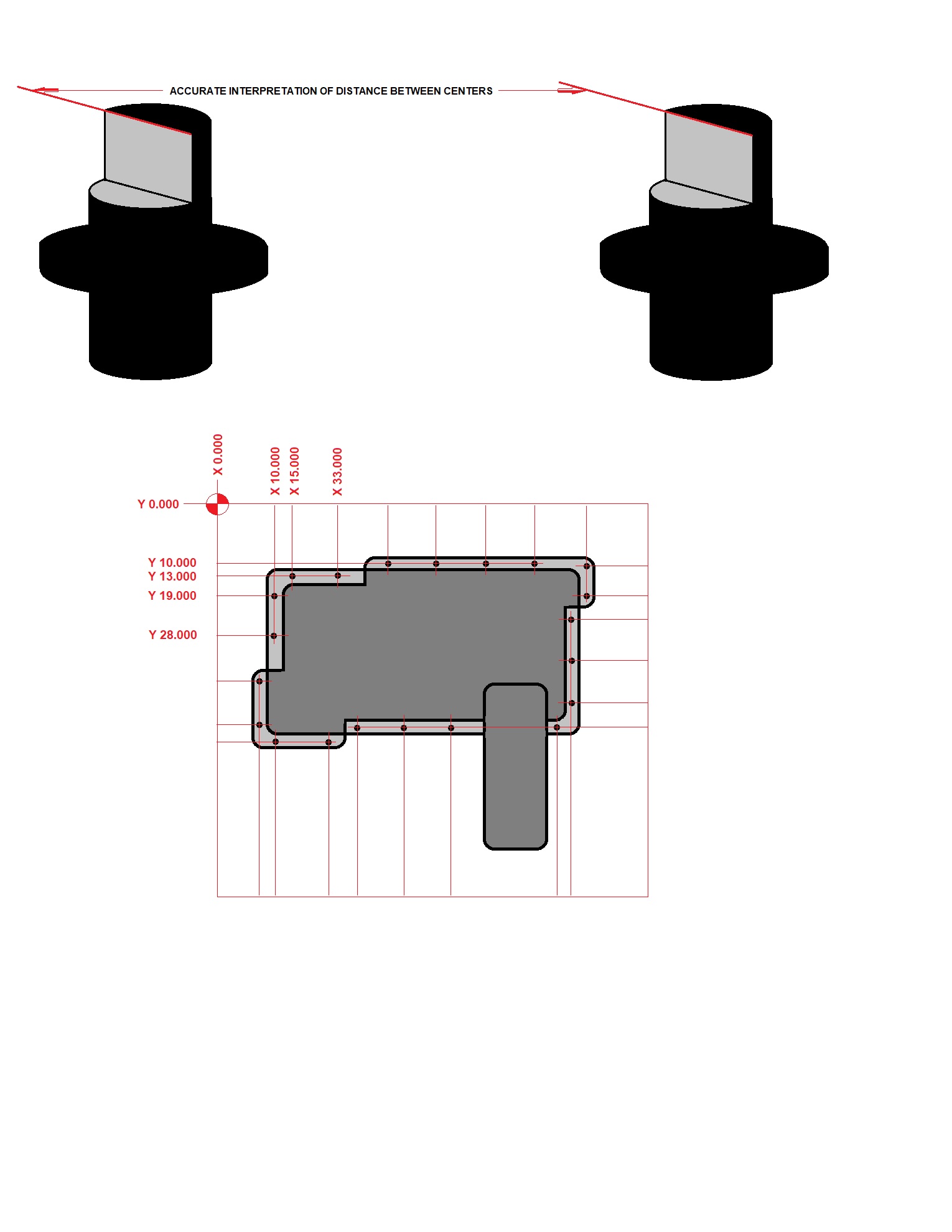
A grid, perfectly workable solution; can envision the process. It's not on skids, just plates so riggers can place toe-jacks to finalize position. That means I can slide tape measure underneath and prove an actual 90-90-90-90 rectangle to divide a grid. Each hole is on the same plane, a few have machine hanging over them. Will make 5-6 ferrous pins, flanged that fit holes with minimal clearance. Above the flange is a boss, milled to a face indicating centerline of pin below. The milled face will hook a tape measure, or attract my magnetic tape, the flange adds weight and stability, the holes are cast not drilled. If necessary, bottom could have a small stud for a wing nut and washer. The halved pins allow accurate center-to-center measurements as well.
Sketch depicts concept, not to size scale or even accurate representation of shape.
Attachment 20550