-
1 Attachment(s)
Just made the crosshead guide or trunk guide.
Attachment 40155
Not quite a scale crosshead for a Burrell, but I wanted something that works at this scale. I might still put it back in the lathe to tweak a couple of the dimensions to make it more compact.
-
1 Attachment(s)
The crosshead guide has been concerning me, so I bolted it to the cylinder. The marking out for the bolts took some time to think about and achieve.
Attachment 40161
The crosshead guide in context actually looks ok, I might thin down the wall thickness. 1.5mm could go down to 1.2mm
-
3 Attachment(s)
Now onto the crankshaft. If you remember my earlier design discussions I was struggling to see a way to getting a 6mm throw and hence 12mm stroke. Well, there are a few things that help this: 1. offset of the cylinder and curvature of the firebox 2. ability to lift the bearing blocks slightly 3. two-piece crankshaft and hence single piece conrod big-end.
So here is a sketch of the crankshaft:
Attachment 40170
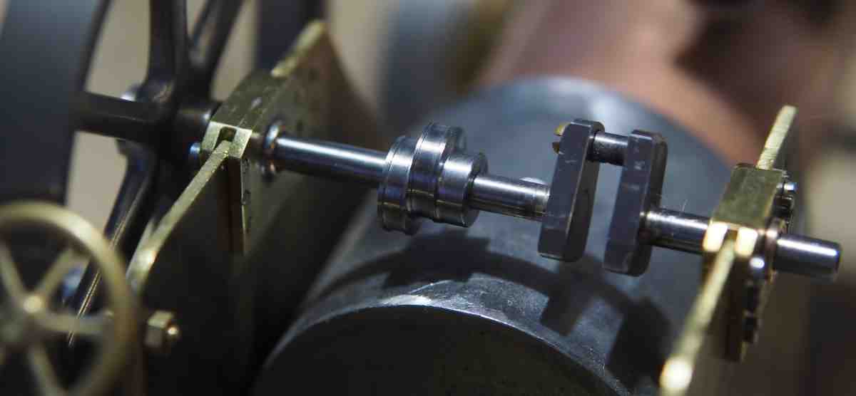
I assembled and silver soldered this with a single piece main shaft. That made it easy to align everything and machine surfaces. One of the last actions was to then split this main shaft and machine back to the internal web faces.
Attachment 40171
Just to prove it still splits into two:
Attachment 40172
-
1 Attachment(s)
I've lifted the bearing blocks 1.5mm and I now have clearance to the firebox
Attachment 40174
it's tight, but that was always going to be a challenge with this 1/20th scale Burrell.
-
1 Attachment(s)
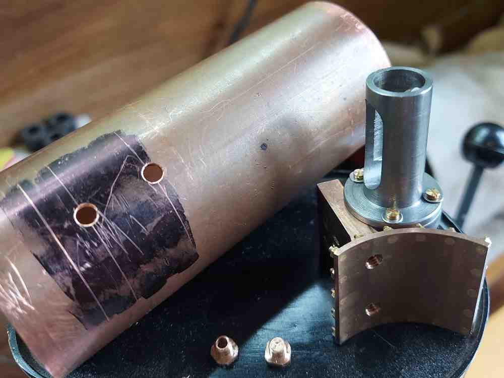
The cylinder saddle is firstly being bolted to the boiler, thus ensuring alignment before I silver solder.
Attachment 40196
The homemade phosphor bronze bolts are to avoid the possibility of dezincification of brass parts that are permanently fixed to the boiler.
-
2 Attachment(s)
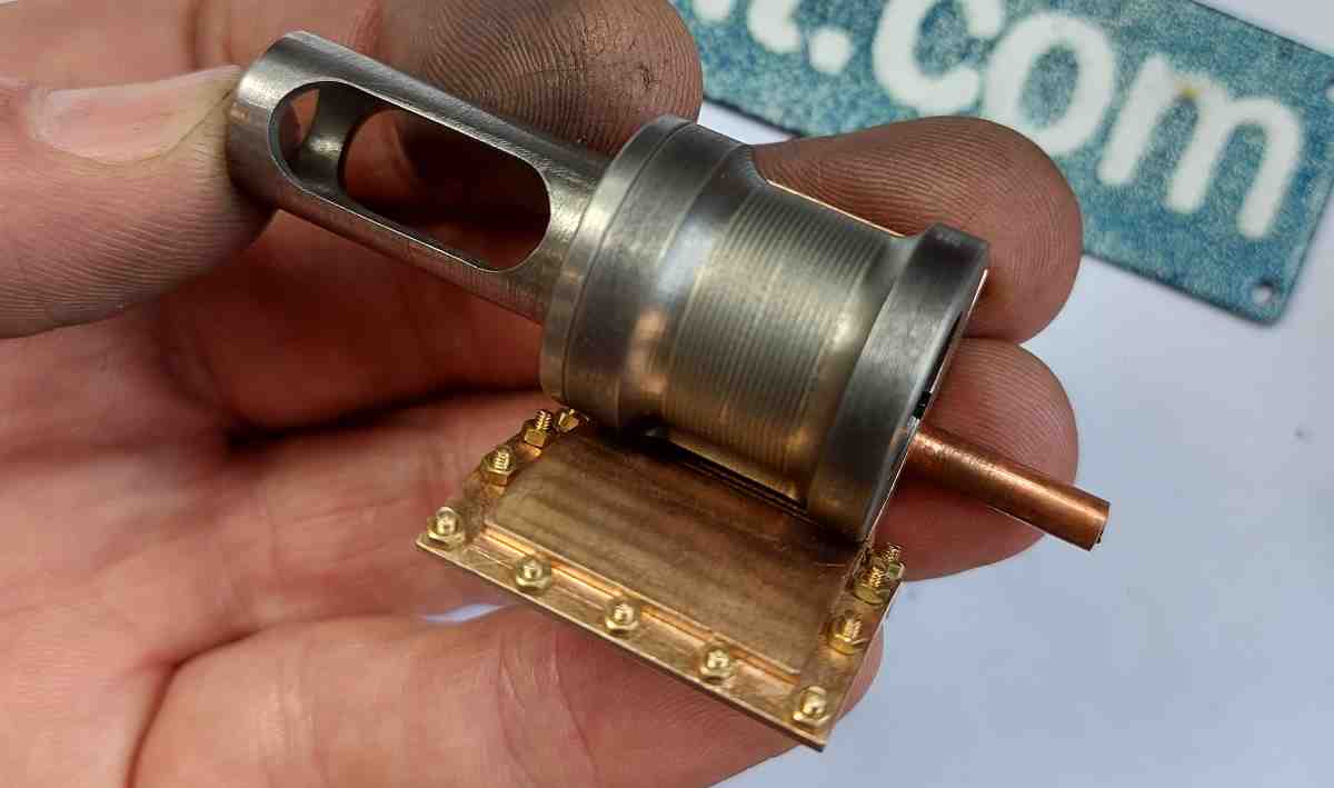
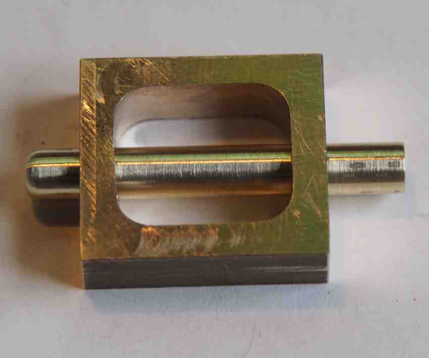
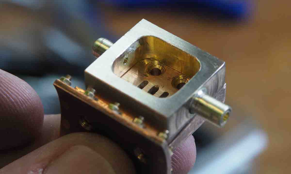
I machined the Burrell valve chest out of a piece of solid brass and then made the centre valve shaft bearings as one.
Attachment 40247
Once this was silver soldered together I then machined out the centre.
Attachment 40248
Hopefully the bearings for the shaft are still aligned.
-
This’d’ve made Joe’s heart glad.
-
The steam valve in this 1/20th scale engine is challenging and so I thought I would talk through the options:
https://youtu.be/q3NyceWqnAk
-
3 Attachment(s)
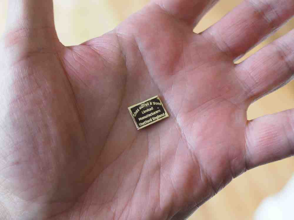
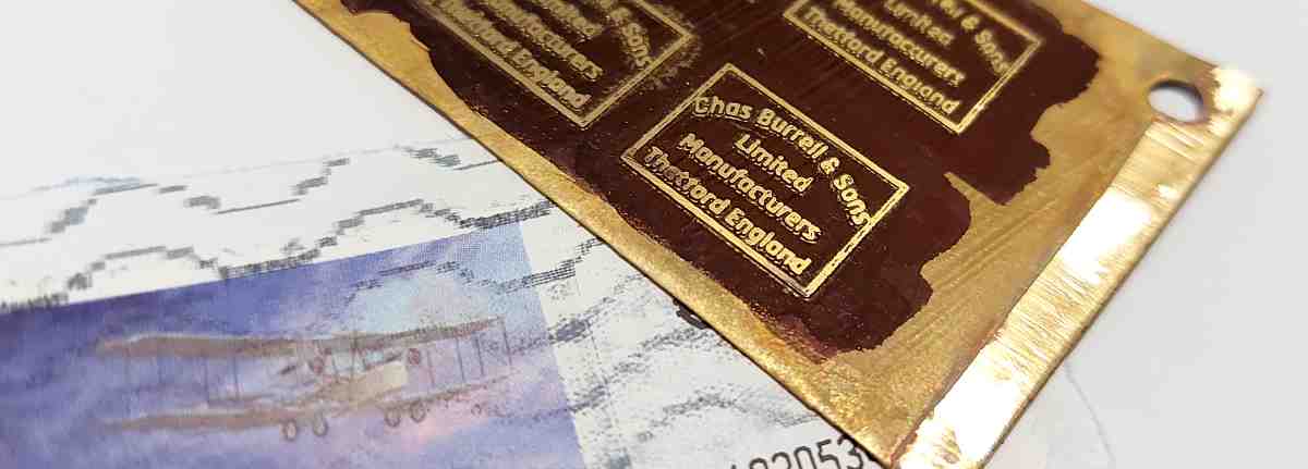
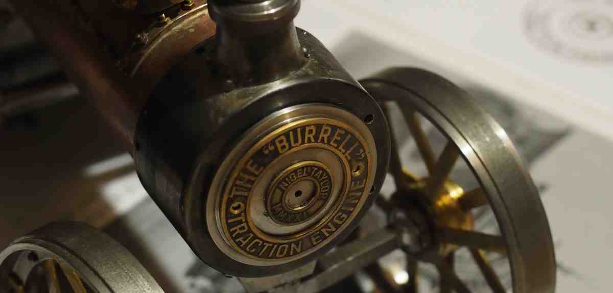
Having machined the valve chest and cover I needed to create the nameplate. At first I thought it should be just a capital N for me, but in the end I decided it should be a proper Charles Burrell nameplate.
The first one was OK:
Attachment 40315
but I thought I should make a few more and select the best.
So, another 4 and I think the best one is this one:
Attachment 40316
The black is just permanent marker for now to give some contrast so I can see if it is ok. In the end it will be painted.
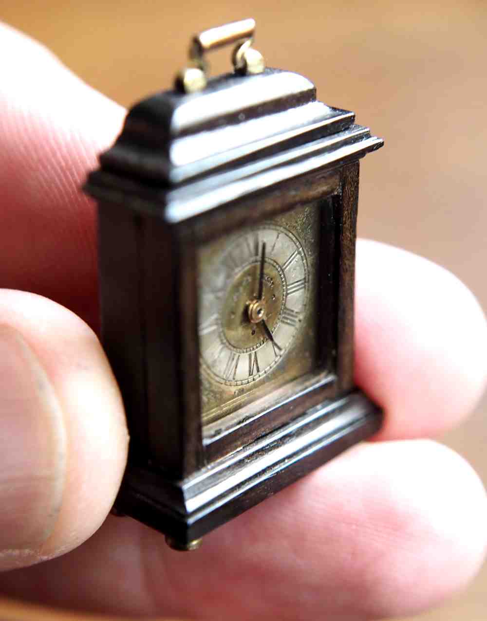
I had a lot to live up to as my dad made this clock and etched the face over 30 years ago. He created the mask using a UV sensitive film and creating a photographic plate (in darkroom he had built into the roof space of my childhood home).
Attachment 40317
PS: this clock keeps good time.
-
1 Attachment(s)
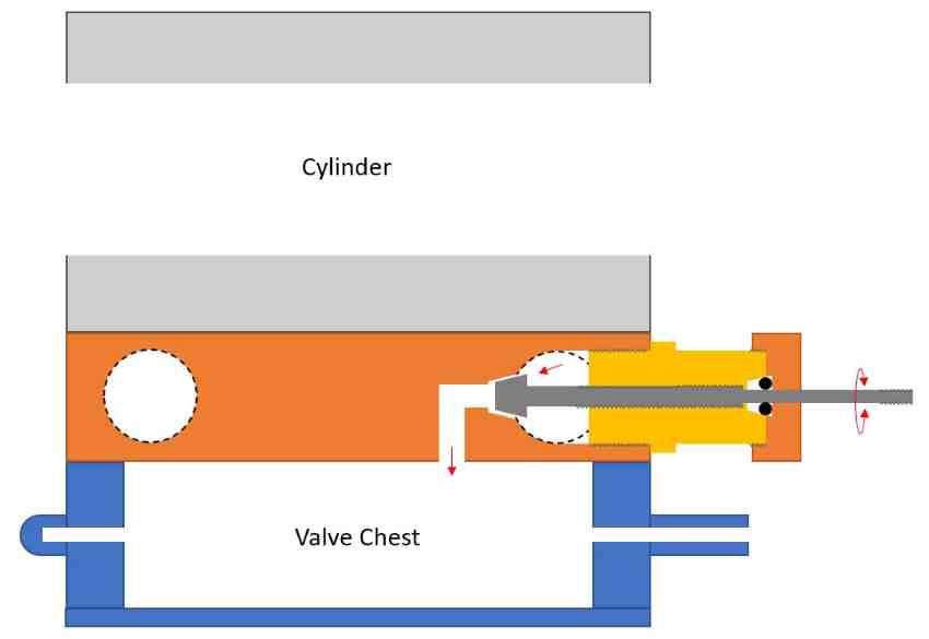
Looking in more detail at the steam valve design. The schematic looks reasonably simple. However, I've been looking at a number of references to try and improve my background knowledge of steam valve design.
Attachment 40354
-
3 Attachment(s)
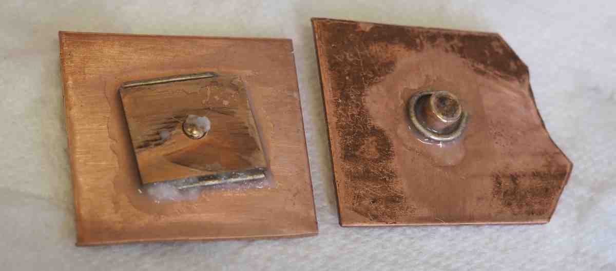
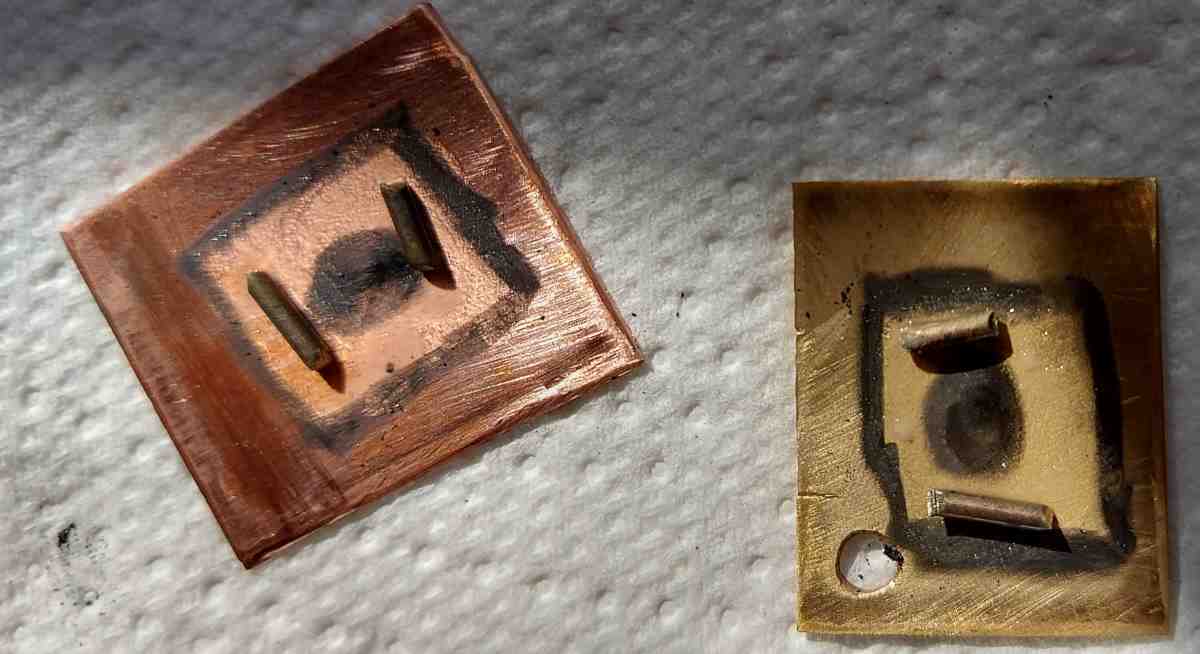
In preparation for silver soldering the phosphor bronze saddle to the boiler I've been running some coupon tests.
Effectively looking at applying silver solder in different locations on the bolted sandwich of copper and phosphor bronze.
Attachment 40359
Interestingly the silver solder happily tracks (capillary action) through the joint, including through the threaded section.
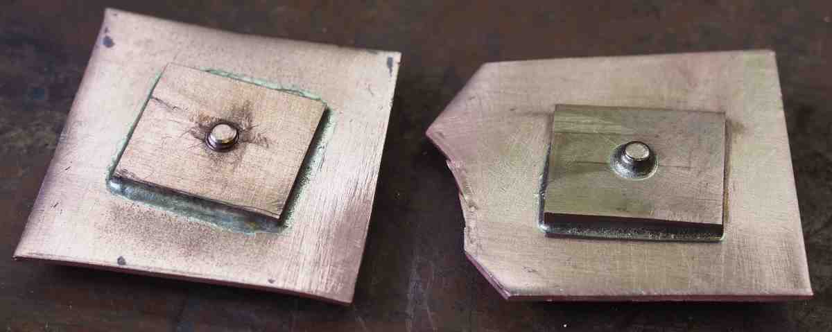
Attachment 40360
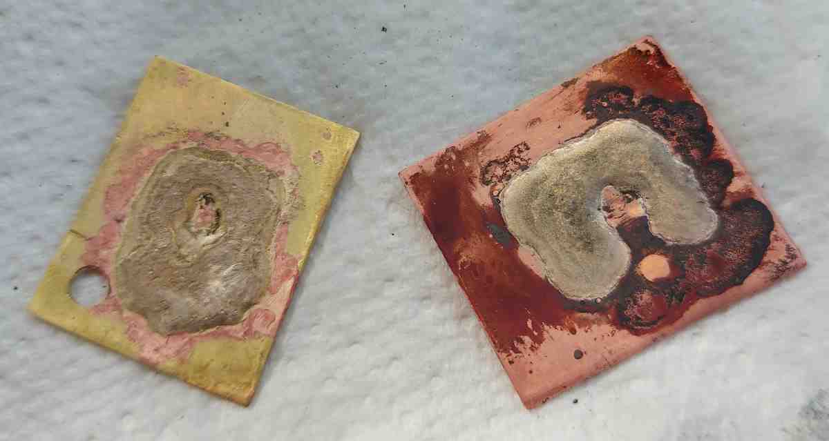
The right hand side configuration appears to have given the most complete joint. I then sectioned the joints:
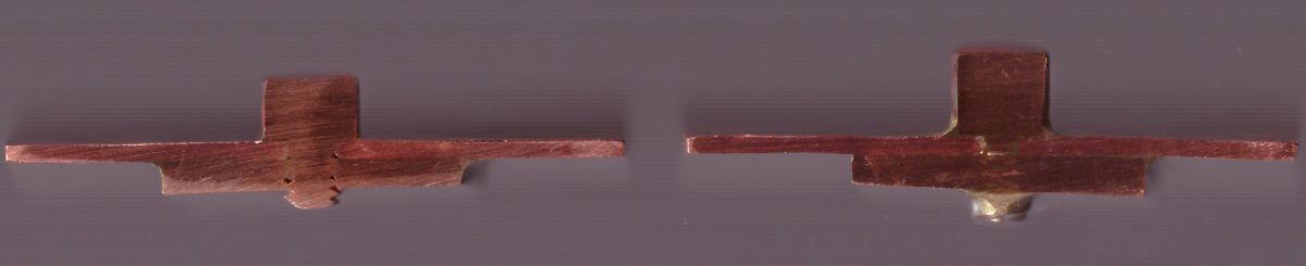
Attachment 40361
You can see that on the LHS the thread of the bolt has voids where silver solder has not tracked completely through all interfaces.
Left and right hand side parts are consistent through the images, although I have had to mirror some of the images to make this consistent (this doesn't affect the results).
-
2 Attachment(s)
Around the saddle I want to mask so that I can control how far the silver solder goes. I did some research and there are lots of options from liquid paper to yellow ochre. However, the option readily available is the graphite pencil:
Attachment 40382
Attachment 40383
This appears to have worked ok.
-
I've been stuck for a few months, a total roadblock on how to make the steam valve. Especially as I have machine this into the PB saddle that itself has had lots of hours put into it. But, after a clean up of the workshop it is back on the bench. I will solve this problem.
https://youtu.be/3imqu2B5IiM
There are a few more items on the list of next things to do on the Burrell
-
1 Attachment(s)
I made the decision to make the steam control valve a remote valve.
https://youtu.be/dOuayWSH-A0
The best bit is I made a decision and this allowed me to move forwards. So I could then silver solder the saddle to the boiler.
Attachment 40944
-
-
1 Attachment(s)
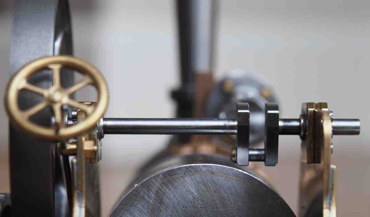
The double eccentric will give me forward and reverse, however, I thought it was going to be tricky machining it. I think it turned out ok.
Attachment 40969
https://youtu.be/M1iXq4brYsc
-
1 Attachment(s)
For the vertical boiler I came up with a multi-layered insulation. For the Burrell traction engine this needs to be shrunk down to 1.5mm in thickness, quite a challenge.
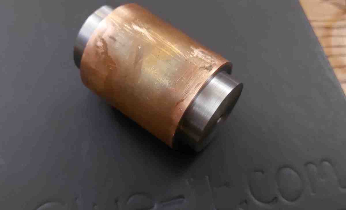
So, I have built a boiler thermal new test object.
Attachment 41054
It's heated in the centre using a 50W ceramic heater (4mm diameter). I will then use the cooling curves to estimate the heat loss.
I will look at the maximum insulation and then a few more sensible options.
-
A short video showing the setup with the end supports:
https://youtu.be/6-Im3rfMguA
Interesting to see the thermal conductivity of wood and where balsawood sits on the curve.
-
1 Attachment(s)
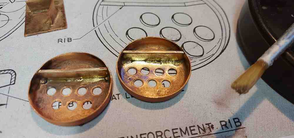
After a lot of help from a fellow steam model engineer I've managed to make and silver solder the boiler end plate stiffeners in place.
Attachment 41069
I think I'm a gluten for punishment pursuing the silver soldering in a kiln. The Easy Flo 24 did not flow as well as some of the lower temperature silver solders.
-
5 Attachment(s)
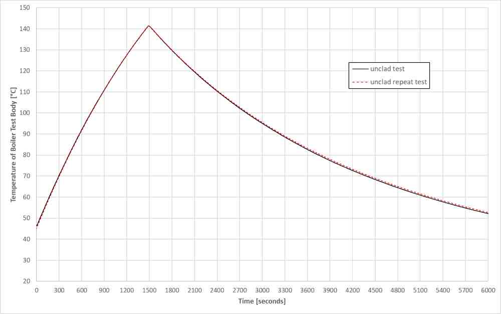
The boiler test object is generating repeatable cooling curves
Attachment 41111
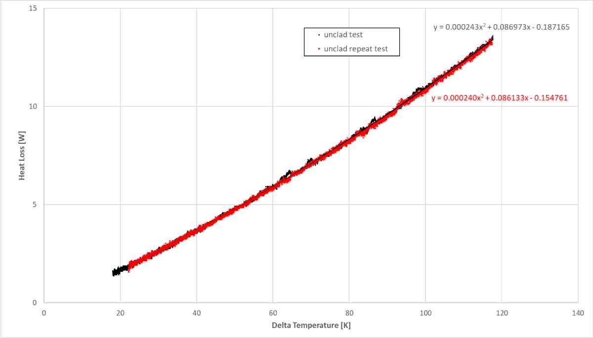
This is great, but what is the heat output of the object
Attachment 41112
So I now have a curve that gives me heat output against a delta temperature compared to ambient.
Next is the maximum insulation versus the unclad boiler:
Attachment 41113
This shows quite a significant difference:
Attachment 41114
Interestingly this boiler is just a piece of copper pipe and so I can compare my heat loss data of the unclad boiler to published heat loss data of copper pipes:
Attachment 41115
That looks like not a bad match considering we don't know the surface condition of the copper pipe.
-
3 Attachment(s)
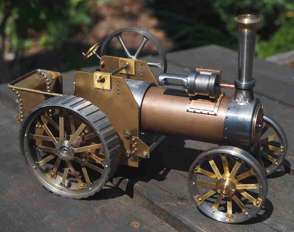
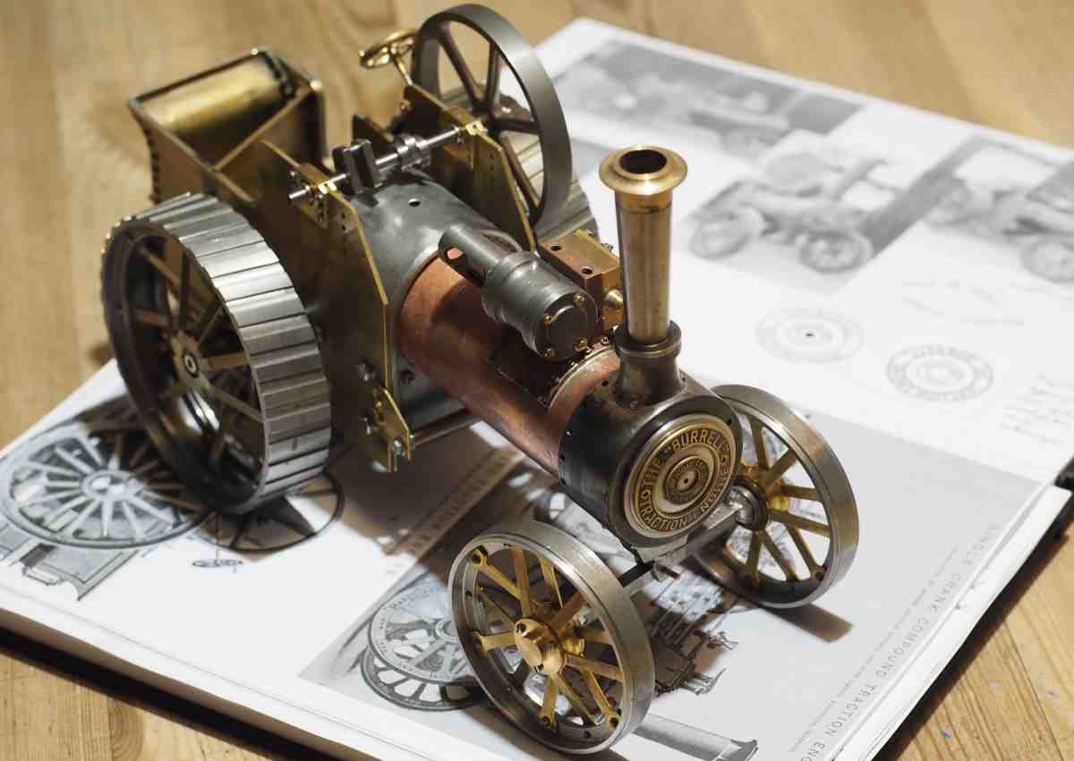
The old flat smokebox door really annoyed me. So, after making a tool to machine a radius of 71.4mm I turned a domed door.
Attachment 41390
I then annealed and pressed the brass plaques to shape, I used a sheet of rubber and two blocks of wood in the vice to do this.
Attachment 41391
It's only a small change, but I think it looks much better.
Attachment 41392
The engine with radiused smokebox door sat on my A4 notebook.
Merry Christmas and Happy New Year to everybody who has supported me over the last year, Nigel
-
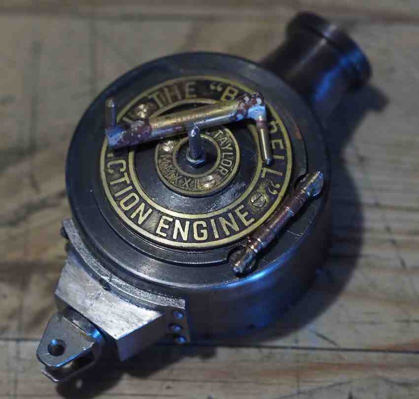
I've now got the door hinge made and the brass plaques bolted to the door. Moving forward again after deciding the flat smokebox door wasn't good enough.
https://youtu.be/M1wJHGfdy3U
-
3 Attachment(s)
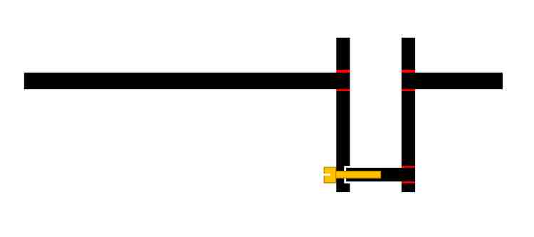
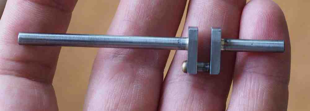
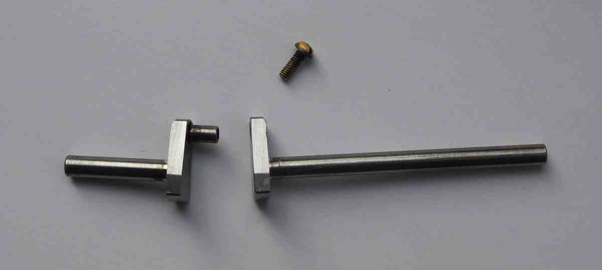
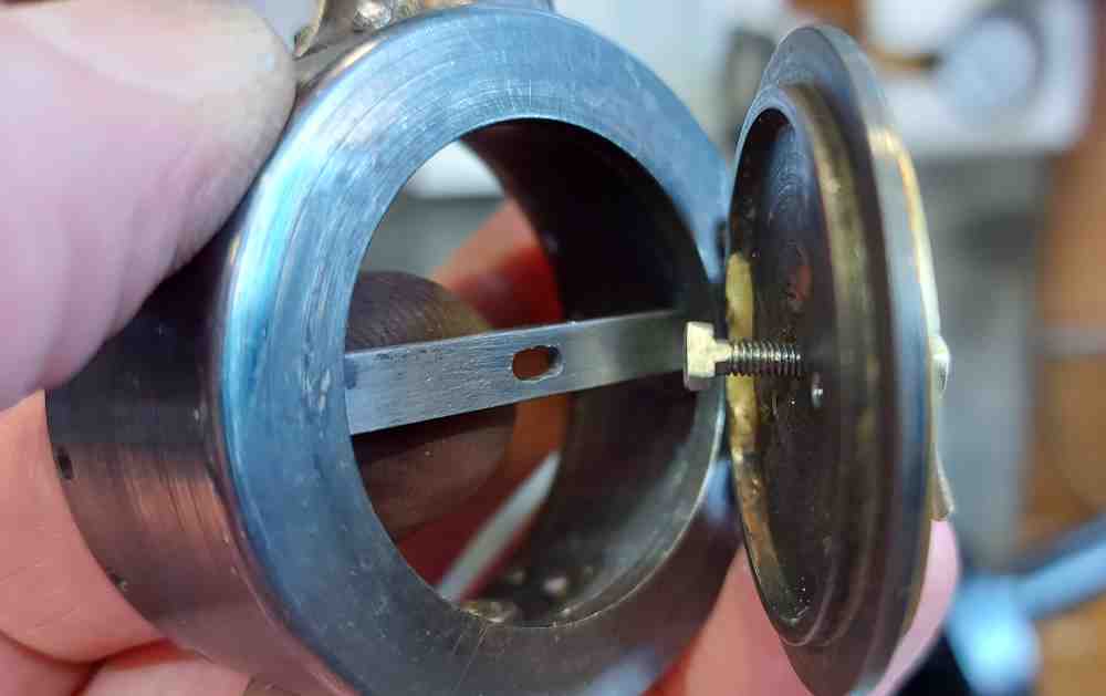
I've now made the Burrell door handles and the locking system, this now all works at 1/20th scale.
Attachment 41541
This hopefully shows the basic locking system.
The Burrell door lock is a T-head bolt with flat sides on the threaded section. This bolt goes through the door from the back, a handle with a slot then goes on allowing the bolt to be rotated. A second handle with a threaded not then allows the bolt to be pulled up tight.
In the smokebox a beam goes across the diameter of the opening and has a slot in it to allow the bolt head to go through. Then the bolt is rotated and hence the T-head gets a purchase on the beam.
Attachment 41542
The handles were made as one part based on them being so small and then I split them into two parts later.
Attachment 41543
Still lots to do
-
I’ve been thinking about the Burrell gearing for some time. Calculating the overall ratio, estimating the maximum torque and speed of the traction engine.
I think 1000rpm is a good top speed for this small double acting engine. The rear wheels are 97mm OD and the gearing gives me around 10:1
My simple calculation says that this will give me 1.1mph or ~0.5m/s which feels reasonable for an engine that might run on my dining table.
This is very similar speed to a Mamod Wagon with 2000rpm, 16:1 and 75mm OD wheels
-
12mm bore at 60psi is ~45N on the conrod
14mm stroke means ~0.32Nm of torque at the flywheel
hence 3.2Nm at the wheel
the drive wheels are 97mm OD and so hence 32N of tractive effort and the engine will be around 1.8 to 2kg
Also, I'm likely to run at a pressure of 45psi mostly and so I think around ~24N
That should be fine
-
3 Attachment(s)
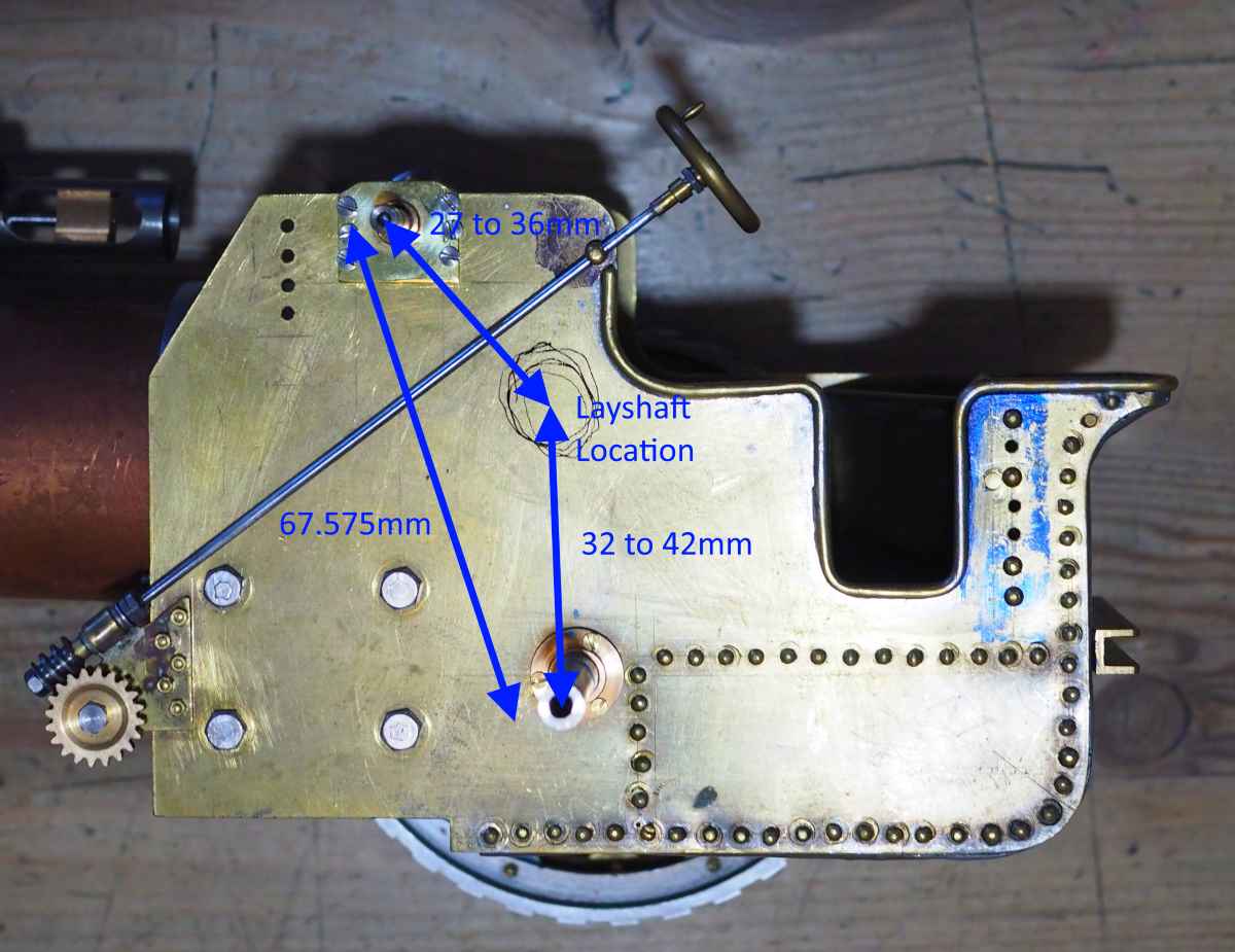
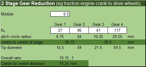
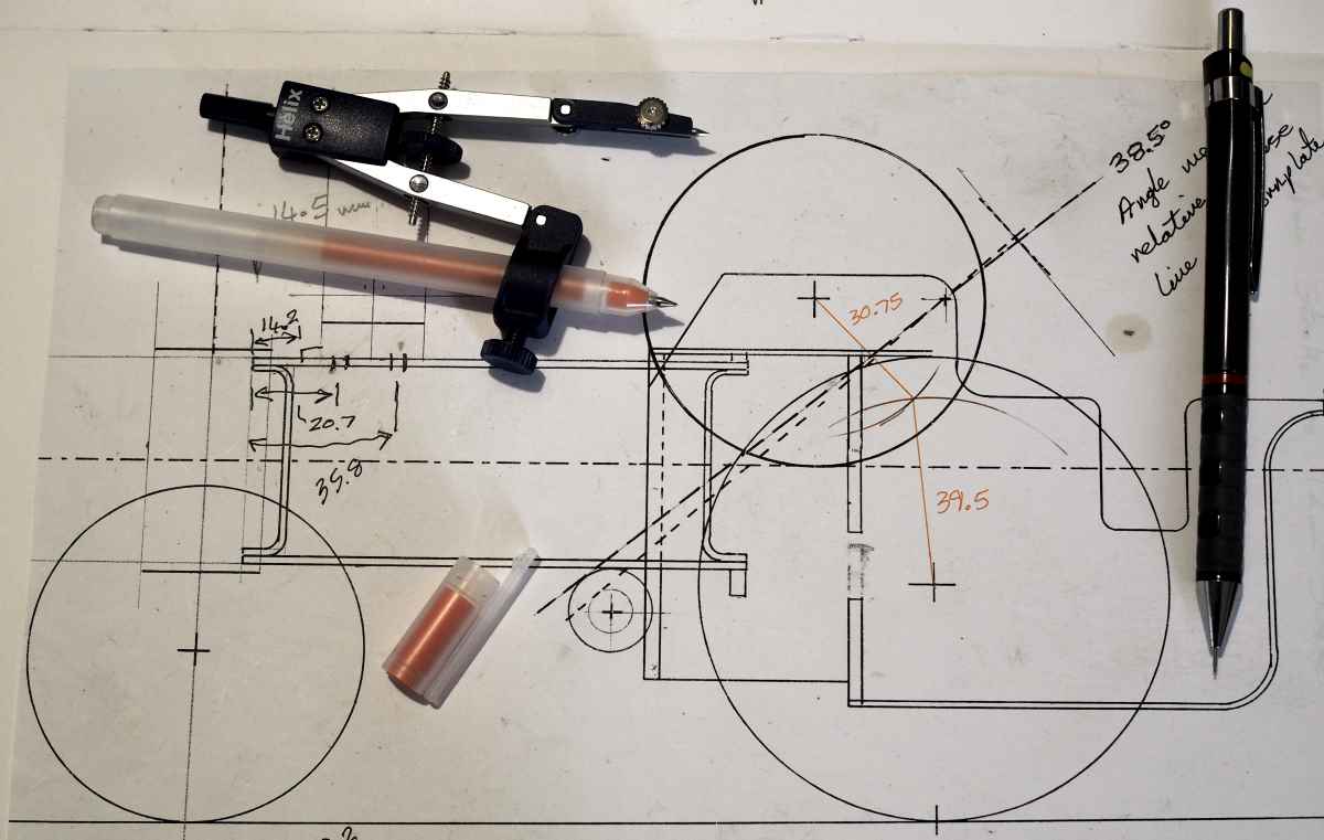
Just been working out how to get to 10:1 as an overall ratio and where the layshaft can go.
Attachment 42019
then some calculations of the options (using excel)
Attachment 42020
and I think I have a sensible result
Attachment 42021
Next step is cutting some gears :)
-
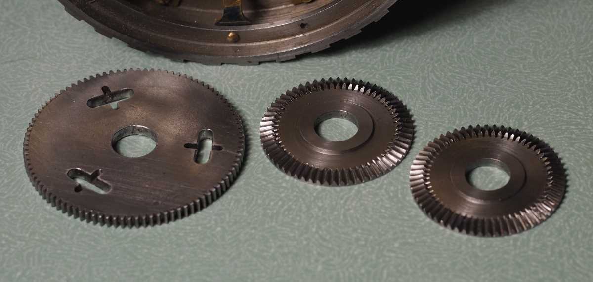
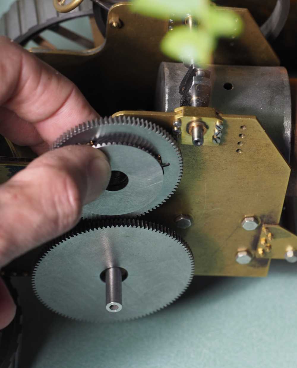
the first prototype differential for the Burrell, some way to go yet, but hopefully you can see what I'm trying to achieve
https://youtu.be/e5L_quO9BUI
-
1 Attachment(s)
a still image of the gears here
Attachment 42075
-
2 Attachment(s)
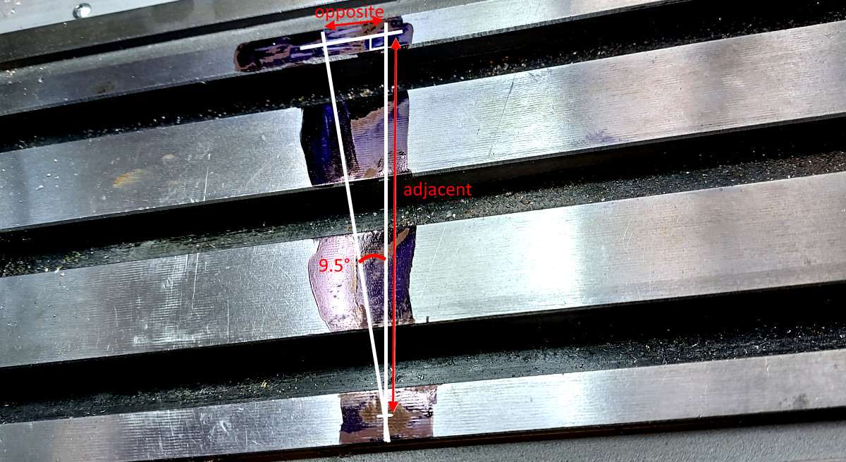
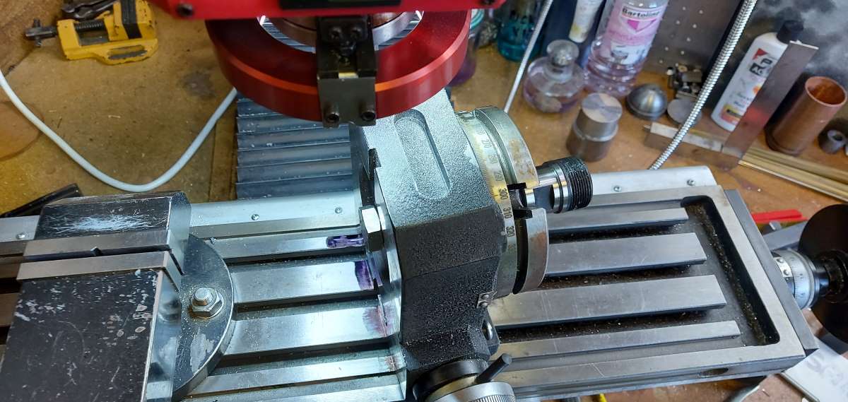
I have to firstly say a huge thanks to JG for sorting out the angles and cutting of these bevels. I thought I knew how to cut them and they would be easy....how wrong I was :sweating:
I spent a happy hour (no drinking) setting out a 9.5° angle on the milling table and then aligning the rotary table to it.
Attachment 42128
Attachment 42129
Now I have to go and cut those gears. Must admit that the cost and effort required in fitting the DRO has been paid back several times over...and it isn't the simplest thing to fit :D
-
3 Attachment(s)
The differential has not started again, but there is a different angle on the Burrell.
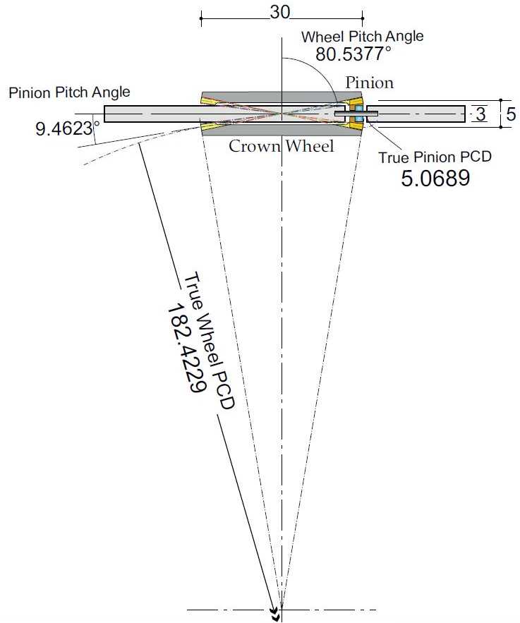
I have to say a big thanks to JG for contacting me and offering to calculate the correct angle for the bevels. As you probably saw in the above youtube they don't run that well. JG's calculations showed that the angle needs to be close to 9.5° rather than 20°, hence last post on setting out the 9.5° on the table.
Attachment 42179
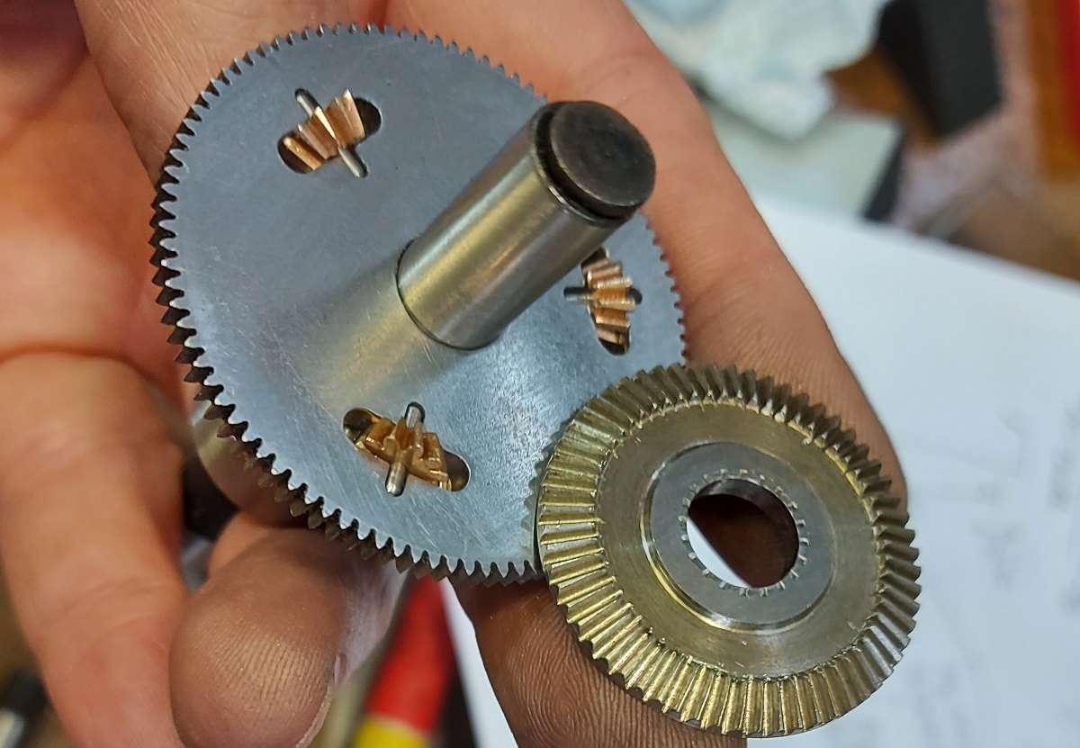
Since then I have managed to re-cut the crown wheels. Perhaps I should not have re-cut them, but there was enough material in them still.
Attachment 42180
plus, this has thinned down the whole assembly. Although, note that the next image isn't using the correct pinion wheels - they are to be made from scratch again as 10T and 9.5°
Attachment 42181
Thanks and remember the whole story of this design and build is in minute detail here: Miniature Traction Engine
-
The differential has taken some time to get to even operate. However, after making some shims to space the crown wheels correctly I have something that operates.
https://youtu.be/NzCnPJZBq4o
I might still re-make this, but for now I know I can get something that works as a differential. In practice it will not actually see that much work and so it is probably ok.
-
I thought this little differential warranted a bit more of a video around it's assembly, the shims and me "running it in" at a stupid speed....
https://youtu.be/O7qYsHtSlTM
-
2 Attachment(s)
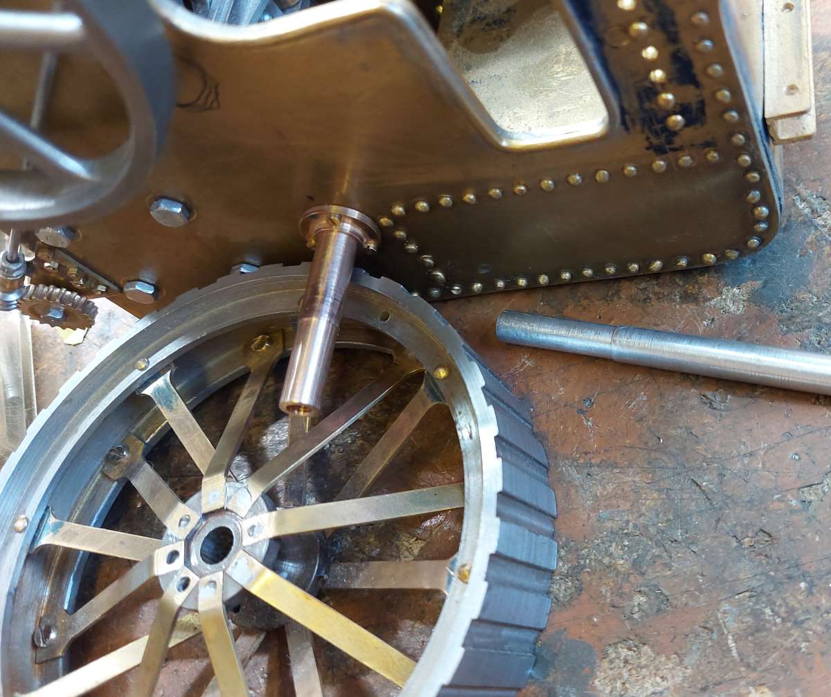
Just machined a solid phosphor bronze rear axle for the Burrell. OK, this isn’t a solid rear axle like a 1960’s muscle car. This is an actual solid round phosphor bronze bar that supports both rear wheels to rotate independently and then the differential sits on a separate layshaft.
Attachment 42990
and then just so that you get an idea of the scale
Attachment 42991
-
-
Just been silver soldering the parts for the rear hub caps and thought I would share the process of using easy flo paste, very easy to get great results on small parts
https://youtu.be/KoZwr0B4y54
-
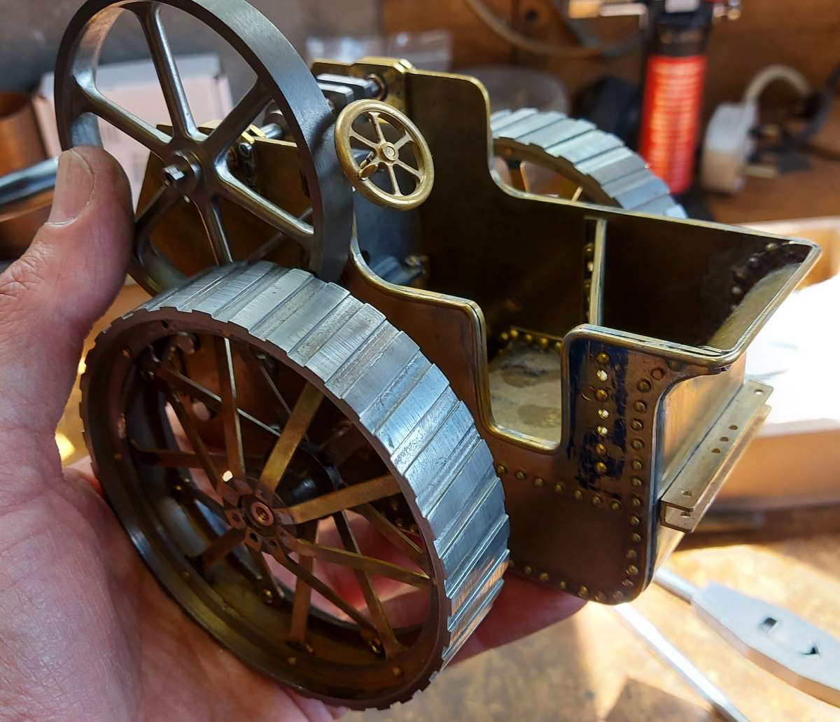
I've had a bit of a break from building this, however, in the last few days I've sorted the rear axle and the rear hub caps. Now I think it is taking shape. On my latest status page of the Burrell Traction Engine there are even more images.
https://youtu.be/QSaq5TVI9U0
-
2 Attachment(s)
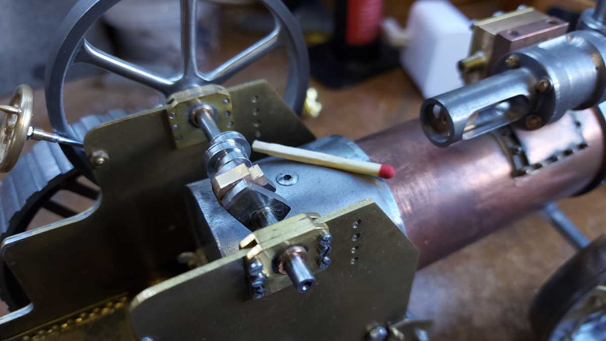
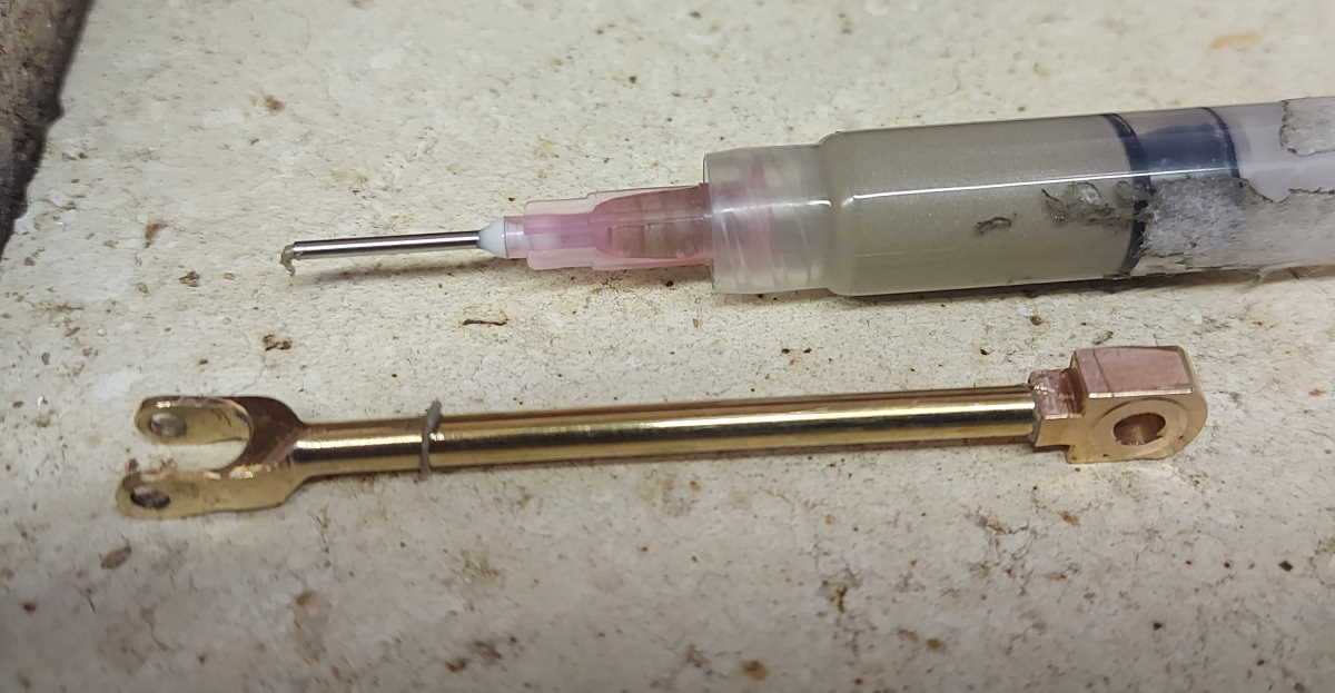
Finally the Burrell is back on the workbench and I've made the connecting rod from 3 parts
Here with the phosphor bronze big end in place. Hopefully the matchstick gives you an idea of scale.
Attachment 44117
The conrod was assembled from 3 parts
Attachment 44118
-
1 Attachment(s)
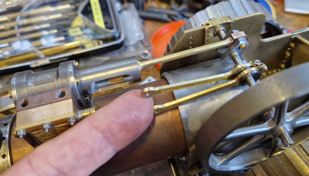
Spent a few hours making the eccentric pushrods and then testing them on a drill:
Attachment 44146
The two eccentrics gives the ability to run the steam engine in forward and reverse. I need to make up the slider, crank and handle etc
https://youtu.be/PeUzvlVP3us
They need a bit more fettling and finishing of the eccentric pushrods, but I'm happy for now.
-
1 Attachment(s)
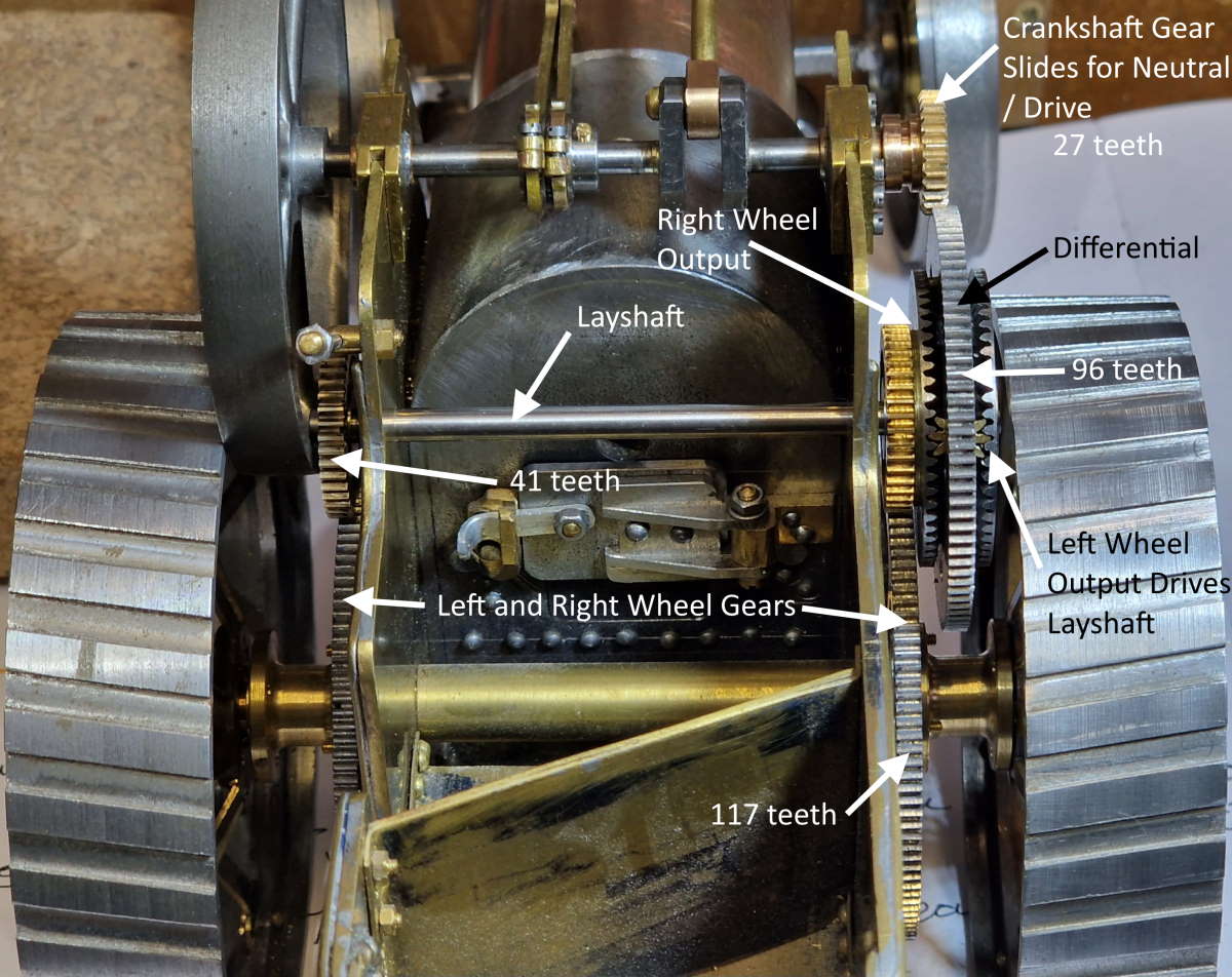
The differential sits on the layshaft and this takes a bit of thinking about. Hopefully the following image helps.
Attachment 44281
The drive and neutral is achieved by sliding the crankshaft gear out of mesh.
https://youtu.be/2C4Lin8xcp4
Lots more to do, but gradually getting closer to completion.