Playing with the nozzle shape will give your heatgun some serious capabilities in smaller or complicated areas.Adding a reostat makes it a super tool for precise temp application.
Printable View
Playing with the nozzle shape will give your heatgun some serious capabilities in smaller or complicated areas.Adding a reostat makes it a super tool for precise temp application.
Could you share what solder you used?
Thanks!
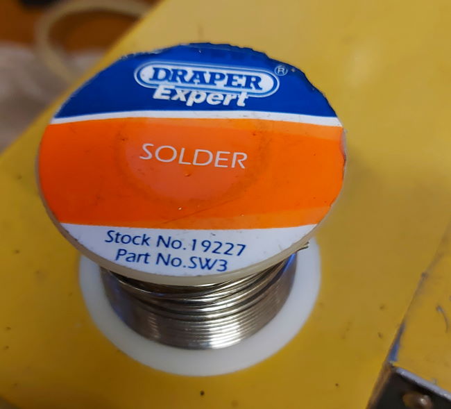
Just taken a picture of the reel of solderQuote:
Originally Posted by Elizabeth Greene
Attachment 38268
Looking this up online: Draper Expert SW3, 19227 250g Reel of K60/40 Tin / Lead Solder Wire - and no longer available as it contains lead.
I haven't tried this with lead free solder, will have to have a go. I must admit that I pick up reels of solder at car boots as these are normally the older lead based solders and much better for a lot of the hobby work that I do.
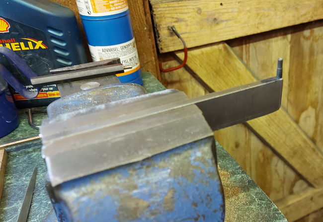
Here's an image of the simple rivet anvil that I made to support the rivet head whilst I hammer it closed.
Attachment 38351
It's made from a piece of 1/4 inch thick mild steel and has a 4mm blind hole in the end. In this hole sits a piece of silver steel that has a concave impression to support the rivet. I hardened and tempered this piece of silver steel. The punch is not fixed in the bracket just in case it needs changing.
Also, I sandwich the mild steel bracket with a sheet of aluminium in the vice as this then adds some compliance and so more easily maintains the clamp load. You might think this piece of soft aluminium would work against you, but it has compliance and so allows the force to be maintained after micro movements of the parts. Either way the anvil stays in place better with the aluminium than without.
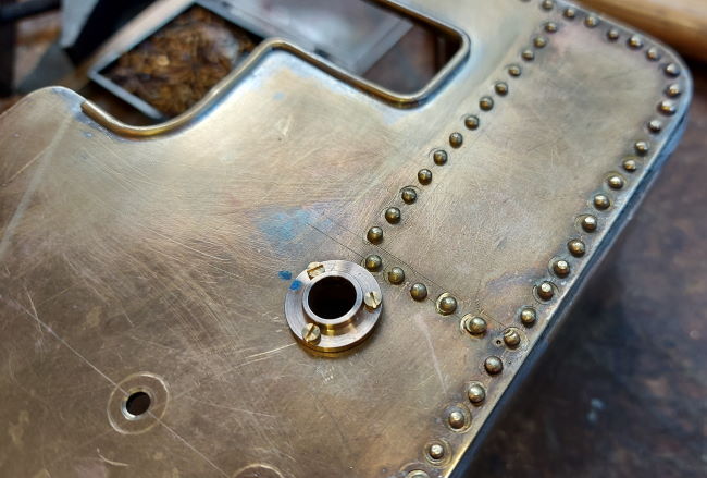
I've machined the Phosphor Bronze rear axle bearings and bolted them into place with 12BA bolts - the 1.05mm diameter tapping drill is difficult to deal with let alone the tap. Anyway, all 6 fixings are in place now.
Attachment 38356
Then I just had to put an axle in place, this is just temporary as I need to make a differential yet
Attachment 38357
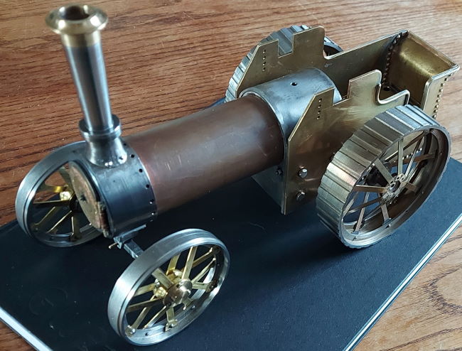
The engine was designed so that the drawing in elevation would fit onto a sheet of A4 paper. Then here it is sat on top of my A4 sized notebook. The traction engine is 263mm long, 122mm wide and 176mm high.
Interesting, but with only the one picture of the rivet anvil, it is very hard to comprehend. A video of this in use would be explanatory I believe. Thx.
Hi, I will see if I can video using it, might have to try some different angles so that it is possible to understand fully. Thanks for the feedback, NigelQuote:
Originally Posted by Wildwilly
Hi Trigger,Quote:
Originally Posted by trigger
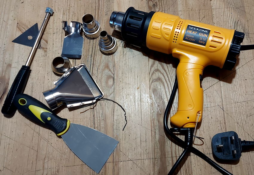
Sadly the old Black & Decker hot air gun gave up after 27 years. So, I had a look around and bought one of these Seekone Heat Guns. It's just arrived, so will see how I get on with it. But, I mention it as it has temperature control (sadly I think open loop) and a range of nozzles that can focus the air:
Attachment 38500
Will update you all once I try it out. Best regards,
I've had some fun making the flywheel for the Burrell. It's only small, but took some work to machine it from solid cast iron.
The initial flywheel design was a tad heavy.
Attachment 38516
So, I had another go at visually improving the flywheel.
Attachment 38517
My quick video of the steps in the process, hopefully you will enjoy the "hand powered belt sander"
https://youtu.be/7Qb1tD5IeeA
<!-- BEGIN /var/www/html/homemadetools/protected/modules/zeus/views/tool/postUpdate.php -->
Thanks editor@glue-it.com! We've added your Rivet Anvil to our Anvils category,
as well as to your builder page: editor@glue-it.com's Homemade Tools. Your receipt:
<div id="blocks"> <div class="block b1 pngfix"> <div class="bimg"> <div> <a href="https://www.homemadetools.net/homemade-rivet-anvil"> <img src="/uploads/247707/homemade-rivet-anvil.jpeg"/> </a> </div> </div> <div class="head pngfix"></div> <div class="left pngfix"></div> <div class="right pngfix"></div> <div class="blockover b1 pngfix"> <div class="title"> <a href="https://www.homemadetools.net/homemade-rivet-anvil">Rivet Anvil</a> <span> by <a href="https://www.homemadetools.net/builder/editor%40glue-it.com">editor@glue-it.com</a></span> </div> <div class="tags">tags: <a href='https://www.homemadetools.net/tag/rivet'>rivet</a>, <a href='https://www.homemadetools.net/tag/anvil'>anvil</a> </div> </div> </div> </div>
<!-- END /var/www/html/homemadetools/protected/modules/zeus/views/tool/postUpdate.php -->
Hi, I film some video of me rivetting the towbar onto the tender, hope this helpsQuote:
Originally Posted by Wildwilly
https://youtu.be/jsn5-HRmO0o
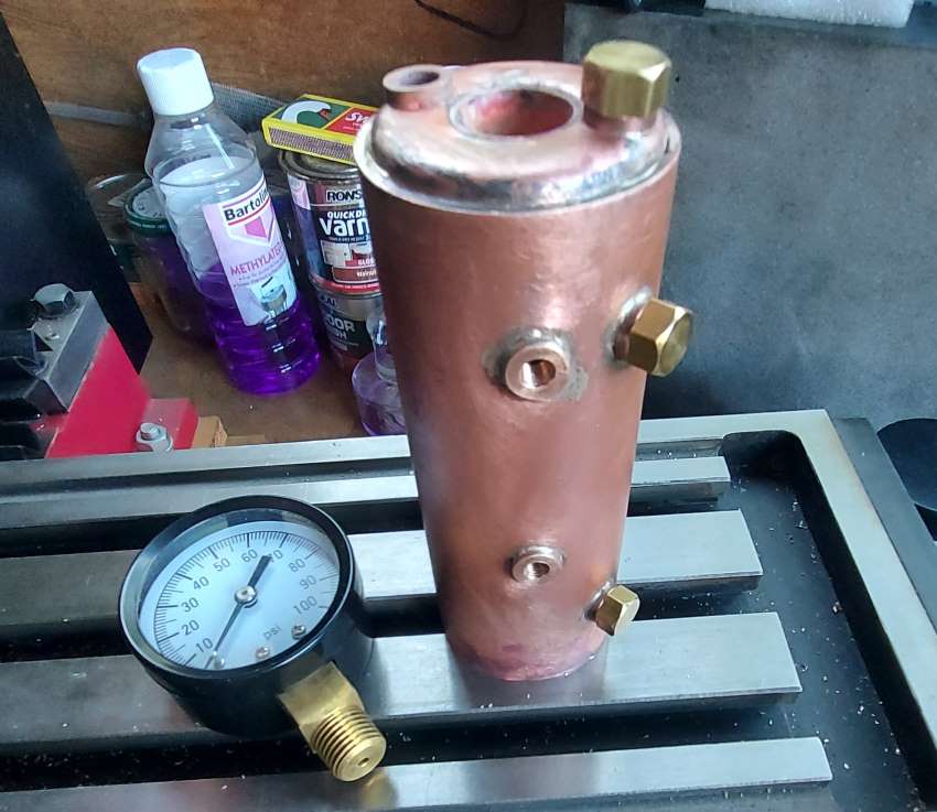
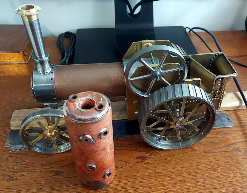
Finally I'm making that small boiler, this is the first boiler I've made. Although it's very small and below the size that requires independent testing (less than 3 bar litre) my plan is to hydraulically test it and do all of the normal sign-off testing that is required.
Attachment 38883
Would be good to hear from people who have experience making boilers and testing them.
This boiler is just 117mm high and you can see it here alongside the traction engine:
Attachment 38888
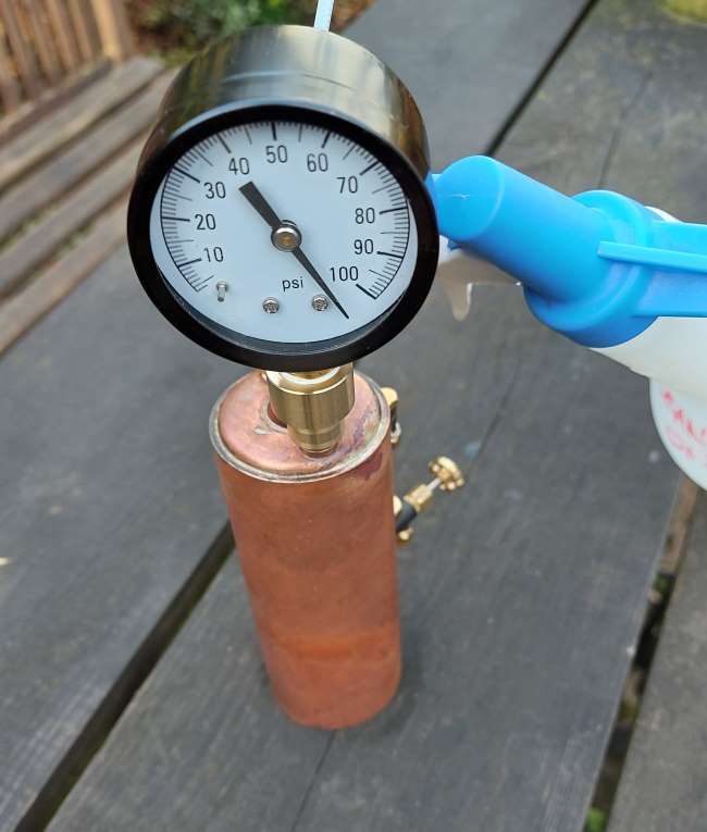
I have now hydraulically tested this to 2x working pressure
Attachment 38889
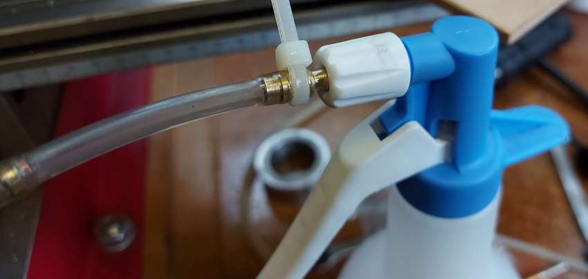
I used a simple garden sprayer - a small modification to the nozzle to fit a pipe. This easily gets to 100psi and I think it would get to 200psi - need a gauge.
I've written a brief article on making the boiler.
I will share more on testing as I need to ensure no issues under steam.
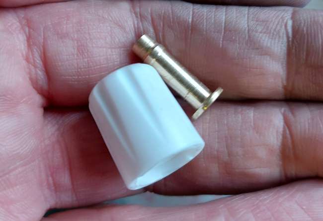
A simple modification to the sprayer nozzle and you have a pump that can pressurize a water volume at over 100psi - perfect for hydraulic testing
Attachment 38926
Attachment 38927
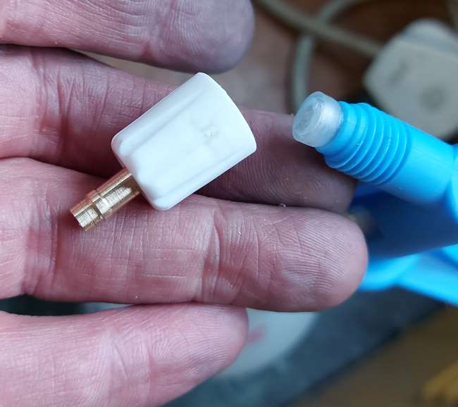
the fixed nozzle of the sprayer seals against the rear flange of the new brass fitting
Attachment 38928
I had to use cable ties to keep the pipe secure on the nozzle with the pressure
Lighting the methylated spirit burner on this small vertical boiler can be quite tricky, I made a slow-motion video to show the problem:
https://youtu.be/dwx8sBaIZfE
Note: don't try this at home
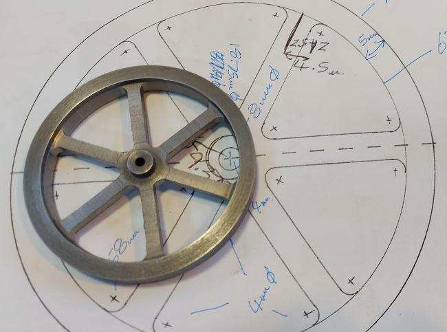
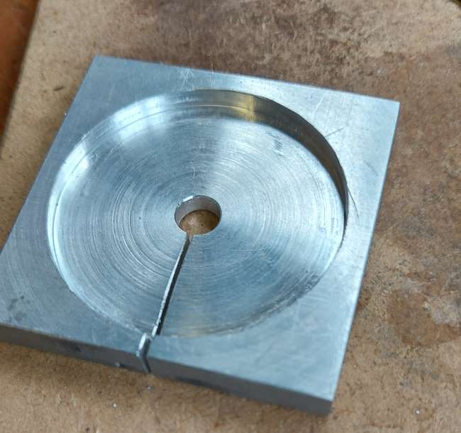
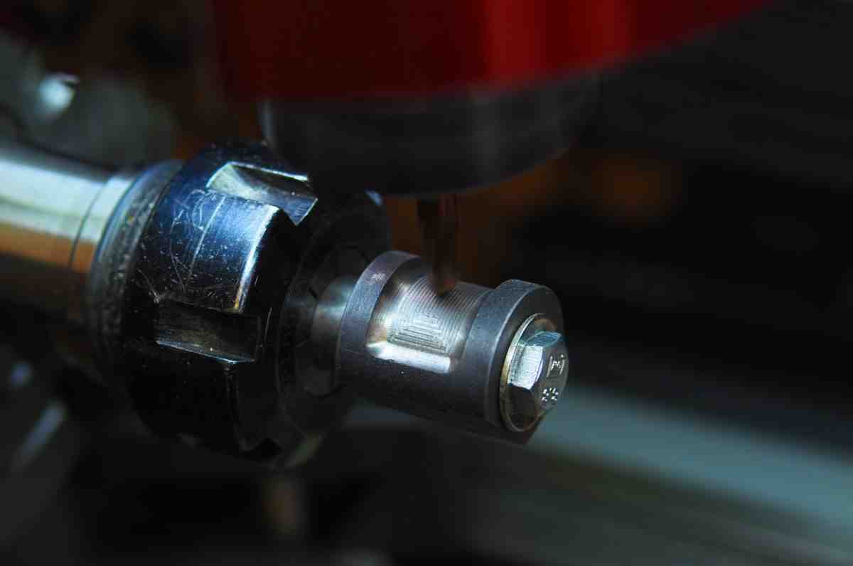
I needed a grate for the fire, but cannot cast iron and so made one from solid. This meant I needed a jig to hold the disc:
Attachment 39002
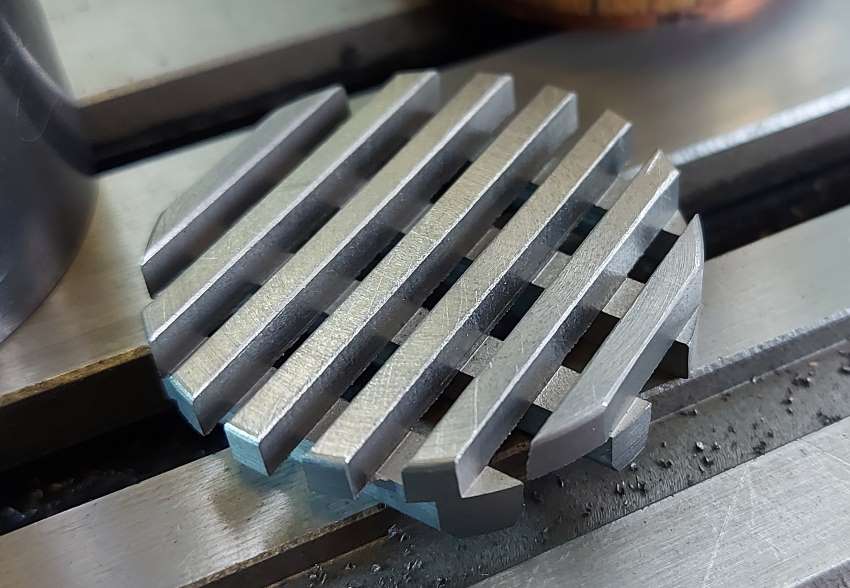
The jig was made from aluminium and it meant I could flip the part over and so machine both sides without damaging it. There were a few steps to making a cast iron grate, but it was very enjoyable. I think the finished part looks good even though you will only ever get a glimpse of this in reality.
Attachment 39003
Interesting, I would have done it using square bars and welded or bolted from the back depending on need.
Surely looks solid!
I do like the look of things that are carved from a block with holes where people might not expect them.
I probably could, but the beams are only 3mm wide and 3mm apart. Welding could be done with solid bars. Not sure I can easily find steel square tubing.Quote:
Originally Posted by jdurand
I agree, there are many ways of doing this.
I'm in the process of making two fireboxes, one for methylated spirit and the other for coal. I know, why?
Attachment 39026
In all honesty I just wanted to have a play and see. This way I can learn about firing with coal and see how hard it is with a tiny boiler. The boiler with the firebox and chimney is just 105mm tall (~4 inches). Air, coal mass, thermal mass, air draft etc is all going to be an issue. I will go through this and share my pains.
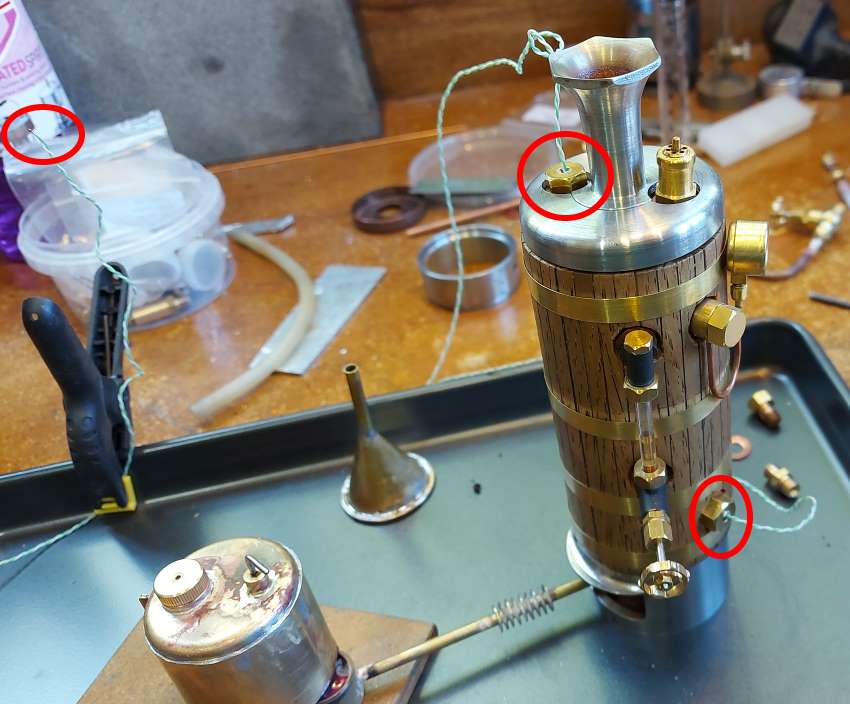
This small boiler is driving me a bit mad, I'm struggling to get the heat into it. It gets to temperature and pressure, but it takes ages considering the meths burner I'm using.
So I decided to instrument the boiler with thermocouples and to then do some measurements.
Attachment 39110
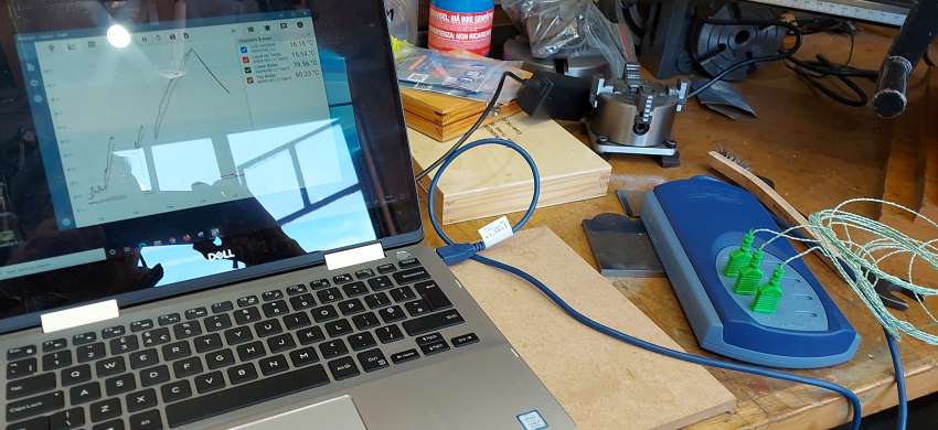
I'm using a Pico Technology measurement board and software, very easy to use. I will share the data and my analysis.
Attachment 39111
Problem with small boilers is surface to volume ration is bad. A lot of radiating surface with a small volume.
Yes, and I've made this worse by making the length versus diameter quite large - the opposite of a sphere...Quote:
Originally Posted by jdurand
However, when I "turn the wick up" on the burner it gets hot very rapidly. So, a lot more work to get the balance of this design right.
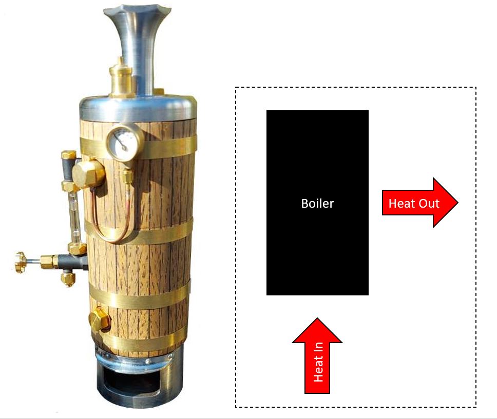
Making some big assumptions I've made a very simple mathematical model of the boiler
Attachment 39124
Then using the cooling curve data I've estimated the heat loss to be 35W at the operating pressure of 40psi (140°C).
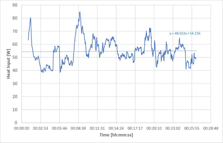
This then allowed me to look at estimating the heat input from the first design of the methylated spirit burner. It is a bit variable, but probably expected as it uses a chicken feeder and there is some air flow.
Attachment 39125
The heat input for this first design is around 54W. This is why I was seeing a very marginal capability for this boiler.
I've now run a few experiments to understand the optimum distance between the spirit burner and the boiler. Normal practice is that the hottest point is at the tip of the inner blue flame, however, there is a depth to the boiler surfaces as shown by this diagram.
Attachment 39205
So, using the simple assumptions, a new firebox and some more measurements on the instrumented boiler I get the following curve:
Attachment 39206
This plot shows that the peak in heat output is when the burner is around 85mm from the base of the boiler. Also, it shows that this firebox and burner is producing nearly double the amount of heat that the original design generated.
I checked this calculation by looking at the boiler temperature versus time data. The original firebox and burner took just under 8 minutes to take the water from 60°C to 100°C. The new firebox and burner took just over 2 mins 30s for this same temperature change. You have to consider heat losses and heat input, but this makes sense.
I wrapped the boiler and electrically heated it so I could estimate the heat loss. This way I could then compare unclad to maximum cladding.
Attachment 39248
At the designed operating point of 40psi and 140°C bulk water temperature the heat loss unclad is ~35W and with maximum cladding it is around 12W.
Attachment 39249
The cladding is a lightweight fleece, then a aluminium coated bubblewrap.
This has made me realise that I could make a low voltage miniature immersion heater - I will post something on this.
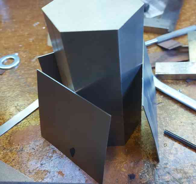
I think I now have most of the parameters for an optimised design of the firebox for the small vertical boiler. At last I can finish it and get back to the traction engine. So, I ordered a bar of 2" mild steel hex. However, when it turned up I just couldn't turn it into swarf....
Attachment 39310
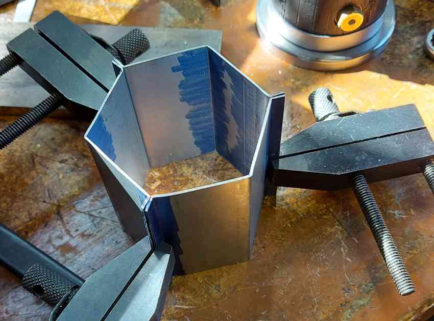
So I thought I could make the firebox from sheet metal, trouble is my sheet metal skills are not that great.
Attachment 39311
However, I'm quite happy with this, now to add a door for the meths burner and some louvres for air.
I've been struggling to get heat into the boiler. So I instrumented it to understand the heat losses and to optimise the burner location.
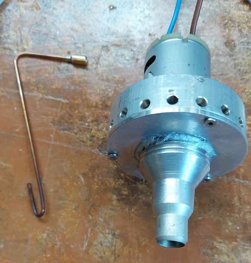
Then I made two types of steam raising blowers.
Attachment 39473
Left: compressed air jet Right: electric suction fan
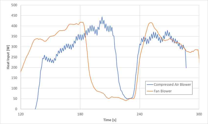
What is interesting is that both give a similar performance. Below is my calculated heat input to the boiler versus time for the two blowers and you can see them switched on, off, on and then finally off.
Attachment 39474
The heat input to the boiler using the simple methylated spirit burner increases from ~50W to ~350W with either blower on.
A video describing the blowers and the data
https://youtu.be/z8NNdBgZJ-o
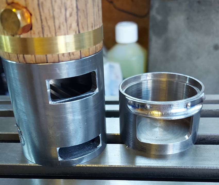
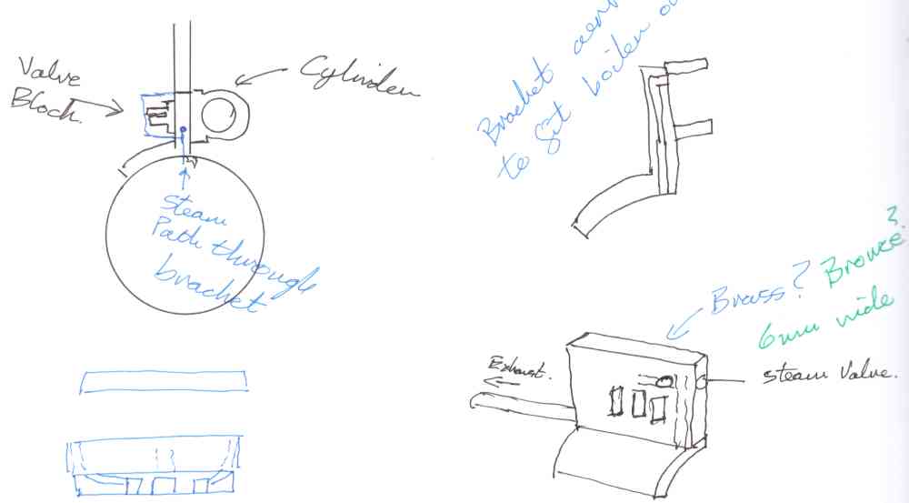
Finally I'm back to the 1/20th scale Burrell traction engine. My new problem to solve and design is the cylinder block.
I have an idea for creating a plate that is silver soldered to the boiler and forms the joint. The cylinder is then mounted one side and the boiler the other.
Attachment 39792
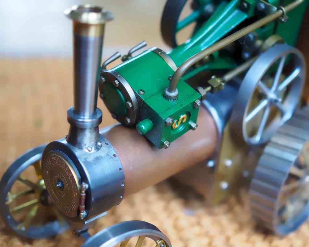
Me offering up the Stuart 10V that is 1.5x too big at 3/4" bore and stroke. The Burrell will be 12mm bore and stroke.
Attachment 39793
This bracket would be easiest made from brass, however, it's best to avoid using brass due to dezincification.
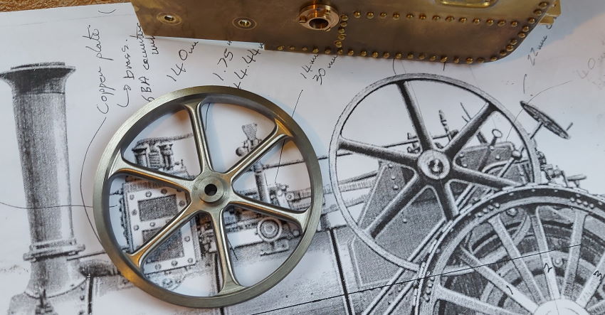
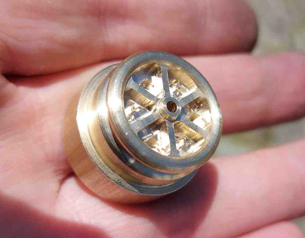
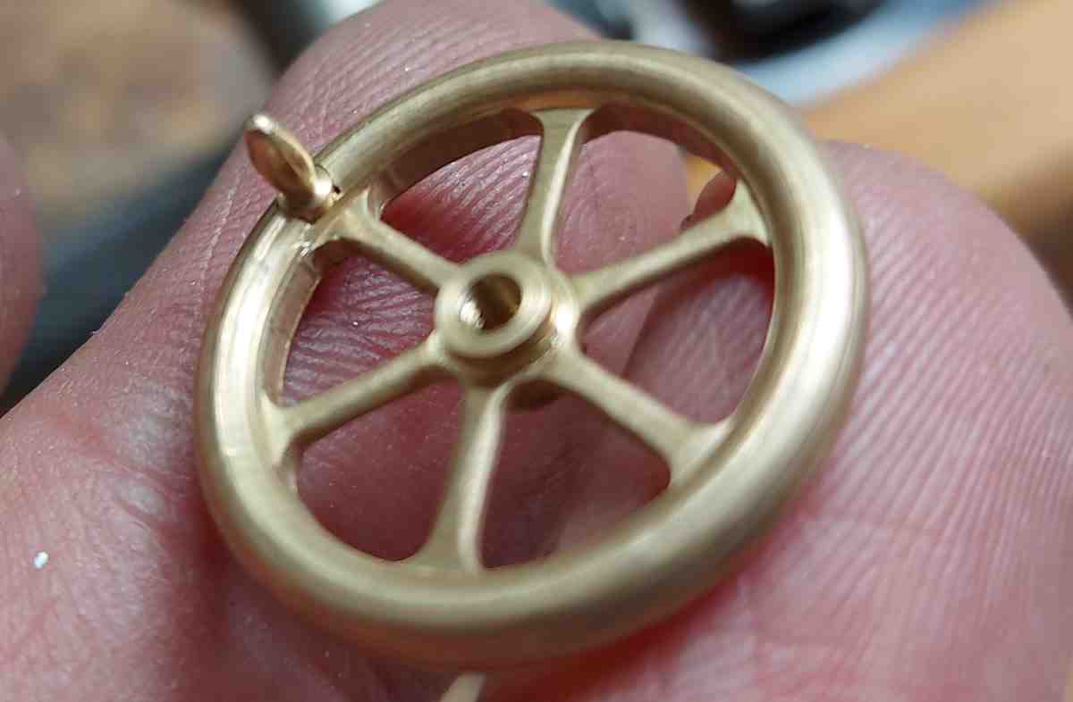
Back onto the traction engine and whilst waiting for material for the cylinder block I roughed out a steering wheel.
Attachment 39838
This is 22mm in diameter (~7/8")
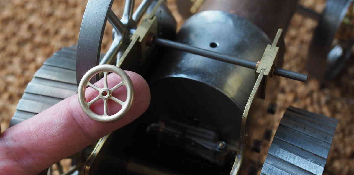
I turned the other side, filed the spokes and then tumbled it for an hour.
Attachment 39847
It's not perfect, might have to make another one, but were traction engine steering wheels perfect anyway?
I've now added a fast handle to the wheel. A complete steering wheel for the Burrell, around 6 hours of work
Attachment 39855
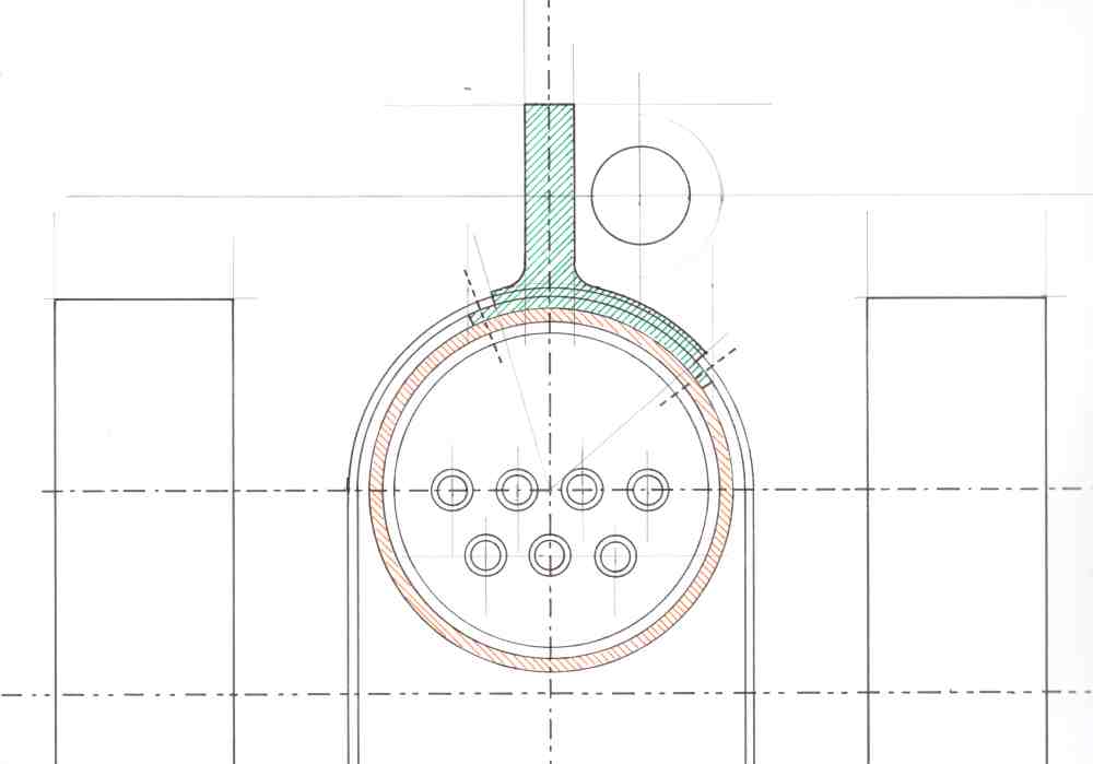
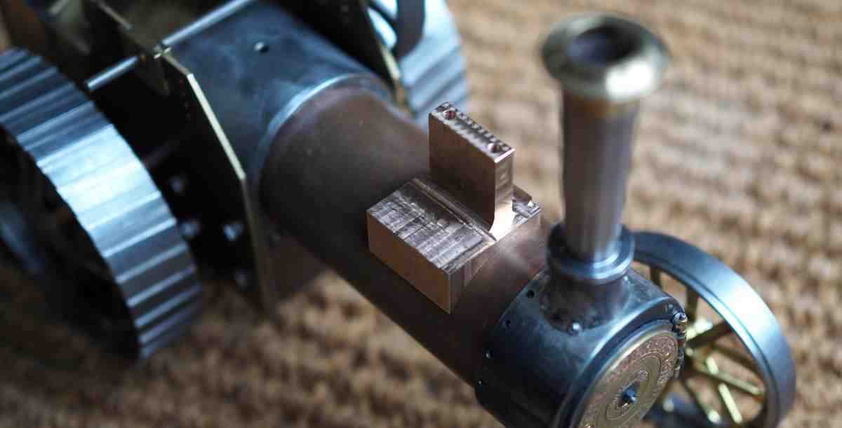
The cylinder block has taken some thought. The single cast iron block bolted to the boiler forming a seal felt difficult to achieve at this scale.
My solution is to create a saddle with an upright backbone that becomes the mounting plate. This part can then be silver soldered to the boiler.
Attachment 39882
This saddle part is shown with the green cross-hatching, the boiler shell with orange cross-hatching.
This is the roughed out part sat on the traction engine
Attachment 39883
That project is wonderful!
very kind, thanksQuote:
Originally Posted by rendoman
I thought it was time to just talk about the Miniature Traction Engine and show everybody how I'm approaching some of the build:
https://youtu.be/hdkOpsqKe3Q
I've been machining the cavity around the Burrell cast iron cylinder.
Attachment 40043
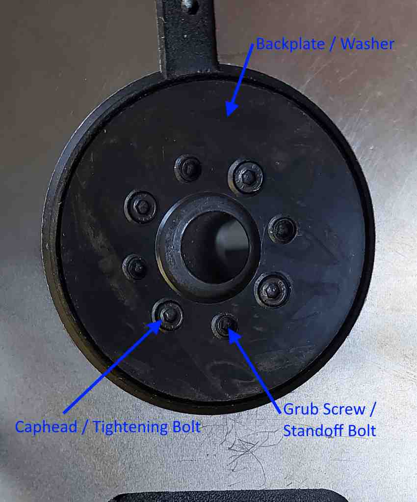
however, my first task was adjusting the HV4 rotary table to remove any play. Not mentioned in the instructions, so I had to find out for myself:
Attachment 40044
I found I had to:
1. rotate the worm drive out of use so the table can be rotated by hand
2. loosely tighten the caphead bolts, not too tight or the table won’t rotate
3. adjust the grub screws so that you can just feel they are bottoming out
4. tighten the caphead bolts, I tighten one and then the opposite one.
5. if you cannot rotate the table then backoff slightly until you can
6. adjust the grub screws to be tighter and so back the washer off
7. you can now use the leverage to feel for play in each direction
8. go back around steps 4 to 7 until the table has no play, but can still rotate
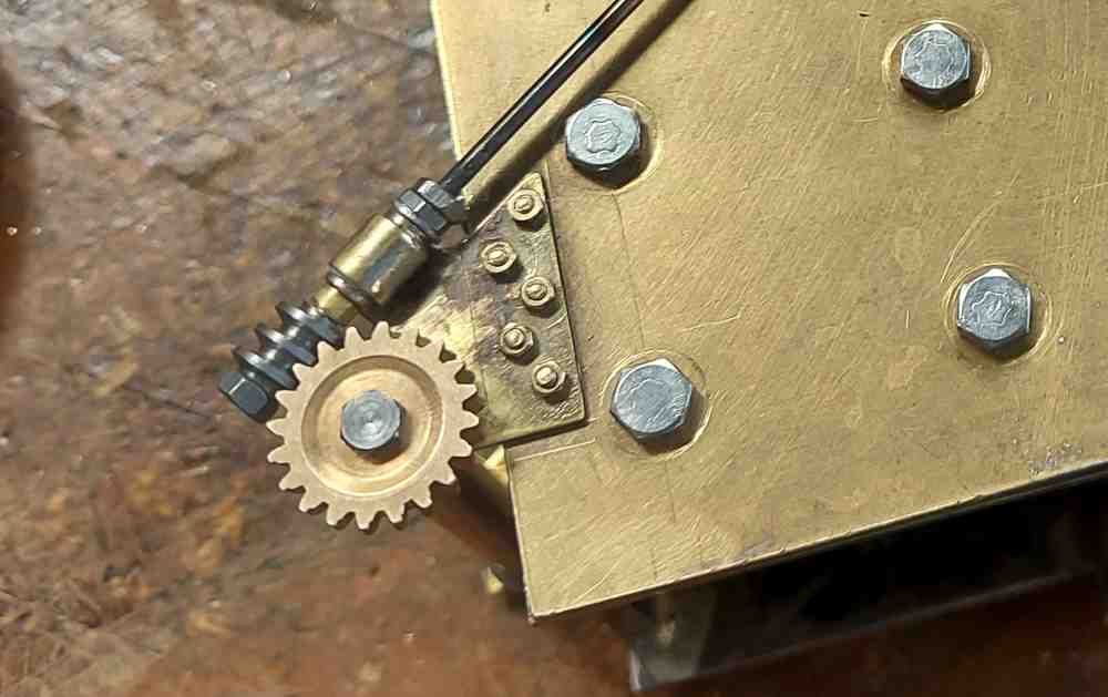
The steering worm and wheel are quite small and so I had to make a 6mm diameter 2mm pitch hob to finish cutting the profile in the wheel.
https://youtu.be/bWsKIFsClv0
Making the parts and assembling the steering bottom end has been quite enjoyable. The worm and wheel are working really well, a really good snug fit.
Attachment 40123
I can now turn the steering wheel and the steering drum rotates. Now I just need to add the chains and I will have a working steering system.
Here is the steering system working
https://youtu.be/njPGn3JL8H4