Free 186 More Best Homemade Tools eBook:  
Get 2,000+ tool plans, full site access, and more.

User Tag List

Page 1 of 2 1 2 LastLast
Results 1 to 10 of 18

Thread: Spring Cut Off Evolution! An Easy to make design + the PLANS

  1. #1
    Supporting Member winkys workshop's Avatar
    Join Date
    Apr 2020
    Location
    Kentucky
    Posts
    161
    Thanks
    1
    Thanked 430 Times in 109 Posts

    winkys workshop's Tools

    Spring Cut Off Evolution! An Easy to make design + the PLANS

    This is the second version of my spring cut-off tool. This design moves the point of flex toward the point of cut which makes the tool retract more under load. The concept is fairly easy to understand (see part one) but the amount of flex and where it flexes is a bit of a guess. I've used the tool at various speeds, feeds and diameters and it seems to be fairly forgiving. I like it!

    186 More Best Homemade Tools eBook

  2. The Following 4 Users Say Thank You to winkys workshop For This Useful Post:

    Claudio HG (Feb 6, 2022), johncg (Feb 6, 2022), Jon (Feb 10, 2022), mtsintra (Feb 5, 2022)

  3. #2
    Supporting Member Toolmaker51's Avatar
    Join Date
    Feb 2016
    Location
    Midwest USA
    Posts
    5,331
    Thanks
    7,042
    Thanked 2,981 Times in 1,893 Posts

    Toolmaker51's Tools
    I wouldn't dismiss spring cut off holders; both history and video proves they work. I use wedge QCTP, and use one every time going in on cast silicon bronze.

    Meanwhile, have noticed over time a feature they lack. As diameter increases, there is a widening of ideal tool height. At same time, every increased load depresses the cutter tip to point, at which a bound cut starts. Rarely will it clear itself. Also, tool relief grinding practices are pronounced in parting tools, the spring can mask.

    Personally, I'd believe the spring works primarily not because it accepts vibration/ chatter of inadequate rigidity, instead gives an extra kick to an overbearing chip load it ejects, that a conventional holder cannot. Parting tools, being HSS or carbide insert have load tolerance, and no signal saying 'too much'. 'Too late', yes that feature is included, FREE!
    Spring cutters were always part of a lantern tool post kit. Those old lathes had all the mass imaginable, but lanterns have notorious overhang from small bearing area, at right angles to cut.

    I think an adjustable stop screw, would allow minimal movement of the tool tip, thereby decrease toolholder 'reaction time', to recover intended height. This certainly would reduce metal fatigue of the spring section as well.
    Without specific metallic analysis and load calculations, any chance combining an ideal material, relief hole, spring section, and position is unlikely.

    2000 Tool Plans
    Sincerely,
    Toolmaker51
    ...we'll learn more by wandering than searching...

  4. The Following 3 Users Say Thank You to Toolmaker51 For This Useful Post:

    Frank S (Feb 5, 2022), NortonDommi (Feb 6, 2022), uv8452 (Feb 8, 2022)

  5. #3
    Supporting Member winkys workshop's Avatar
    Join Date
    Apr 2020
    Location
    Kentucky
    Posts
    161
    Thanks
    1
    Thanked 430 Times in 109 Posts

    winkys workshop's Tools
    Quote Originally Posted by Toolmaker51 View Post
    I wouldn't dismiss spring cut off holders; both history and video proves they work. I use wedge QCTP, and use one every time going in on cast silicon bronze.

    Personally, I'd believe the spring works primarily not because it accepts vibration/ chatter of inadequate rigidity, instead gives an extra kick to an overbearing chip load it ejects, that a conventional holder cannot.
    The top of this blade is shaped to make the chips more narrow than the cut (HHIP 2000-7030 3/32 x 11/16 x 5 Inch 5% Cobalt P3N Style Parallel Type Cut-Off Blade) so the chips never get stuck. I love this blade. I think the spring action compensates for the inward tilt of the tool post flex. With a normal blade holder the point of flex is below the tool and when the tool grabs it is also pulled into the work. When the point of flex is on top the blade pulls back. I don't think it actually pulls back but it lets the tool post flex without puching the blade into the cut.

  6. The Following 3 Users Say Thank You to winkys workshop For This Useful Post:

    Frank S (Feb 5, 2022), NortonDommi (Feb 6, 2022), uv8452 (Feb 8, 2022)

  7. #4
    Supporting Member Frank S's Avatar
    Join Date
    Aug 2015
    Location
    Peacock TX
    Posts
    11,224
    Thanks
    1,985
    Thanked 8,788 Times in 4,207 Posts

    Frank S's Tools
    Might be worthwhile to place a few dial indicators in strategic places checking any movement from the carriage to the cross slide the compound "if used " the tool posts and a couple places along the blade itself. Film in the highest resolution available then play back frame by frame. I have a hunch you both may be partially right and partially wrong at the same time. I would have toi make one to test my theory though, and after seeing how well yours appears to work I may just have to do that. once a few million other bucket list projects wind down.
    Never try to tell me it can't be done
    When I have to paint I use KBS products

  8. #5
    CanBeDone's Avatar
    Join Date
    Oct 2019
    Posts
    43
    Thanks
    0
    Thanked 38 Times in 18 Posts
    If you want to look at the original Armstrong tool, here is the catalogue: https://archive.org/details/Armstron...rsCatalogTHB49
    If you want dimensions. here they are: https://www.hobby-machinist.com/thre...-holder.80037/
    If you want the standard explanation of why the Armstrong tool works, here it is:
    - see minute 3:02 for the simulation

    What intrigues me is why Winky's second version failed, and, in his claims, the third version is even better than the first. These claims seem to indicate that the standard explanation is wrong. But is it? This is a question only Winky may answer, as only he has access to the three tools.
    For guidance, if a tool chatters, this indicates that the cutting forces at the cutting edge of the tool are higher than the stiffness of the setup, enabling resonance. To decrease cutting forces, the standard arguments are "Sharpen the cutting edge" and "lubricate", both of which Winky has emphasized, but without linking them to chattering. The standard explanation adds a third argument: "temporarily reduce the cutting depth by withdrawing the tool whenever the tool encounters a hard spot on the material", which also results in a reduction of cutting forces.

    Onset of chattering is rather abruptly, because it is a resonance effect that relies simultaneously on the magnitude of the stimulating force and the stiffness of the setup resisting this force. Adding friction to it changes the chattering frequency somewhat, but usually not that much. What I suspect has happened in his spring tools is that all three of them operate close to the force limit at which chattering starts, two being on the good side and one being on the bad side by sheer bad luck. I am a bit skeptical about FrankS ' suggestion of using DTIs to measure deflections: Is the inertia of the DTIs low enough to follow the tools movements?
    My approach would rather be to lower the stiffness of the bad tool by grinding off some material where it influences stiffness most.
    Winky.pdf
    The most critical dimension is the distance measured along the red line, as it enters the appropriate equations as a fourth power, and thus even small changes would have a substantial effect.
    If you still have the bad tool, shortening that distance by grinding off some material is the easiest way to find out. A weaker neck would also imply a reduced feed rate, but that is a small price to pay if a tool can be salvaged. Knowing whether this works I believe, all of us would profit.

  9. The Following 11 Users Say Thank You to CanBeDone For This Useful Post:

    asterix (Feb 8, 2022), bustre00 (Feb 12, 2022), Corm (Feb 13, 2022), emu roo (Feb 7, 2022), Floradawg (Feb 8, 2022), freddo4 (Feb 12, 2022), johncg (Feb 6, 2022), NortonDommi (Feb 6, 2022), nova_robotics (Feb 12, 2022), rgsparber (Feb 12, 2022), Toolmaker51 (Feb 6, 2022)

  10. #6
    Supporting Member winkys workshop's Avatar
    Join Date
    Apr 2020
    Location
    Kentucky
    Posts
    161
    Thanks
    1
    Thanked 430 Times in 109 Posts

    winkys workshop's Tools
    Quote Originally Posted by Frank S View Post
    Might be worthwhile to place a few dial indicators in strategic places checking any movement from the carriage to the cross slide the compound "if used " the tool posts and a couple places along the blade itself. Film in the highest resolution available then play back frame by frame. I have a hunch you both may be partially right and partially wrong at the same time. I would have toi make one to test my theory though, and after seeing how well yours appears to work I may just have to do that. once a few million other bucket list projects wind down.
    The only negative I have found is that when its at the end of the cut it leaves a nub due to the lack of SFPM. It you lathe has speed controls on the fly speeding it up at the end would help a lot.

  11. #7
    Supporting Member winkys workshop's Avatar
    Join Date
    Apr 2020
    Location
    Kentucky
    Posts
    161
    Thanks
    1
    Thanked 430 Times in 109 Posts

    winkys workshop's Tools
    >>> The most critical dimension is the distance measured along the red line, as it enters the appropriate equations as a fourth power, and thus even small changes would have a substantial effect.
    If you still have the bad tool, shortening that distance by grinding off some material is the easiest way to find out.

    Wow... a scientific group here! Haha... thanks for your interest. I like it.

    I think you overlooked one aspect and in my opinion it is a key. I do like the idea of slowly grinding away the thickness at the red line. I thought about doing the same. However, I think what is being overlooked it the position of the pivot (or point of flex). The second design (3rd tool) used 3/8" stock (instead of 1/2") but with about the same thickness the other direction so it should flex easier. However, I think the position of the hole as it relates to the cutting point is key. It's moved forward about 1/2". This makes the tip of the tool move back more inward with a given amount of downward deflection.

  12. #8
    CanBeDone's Avatar
    Join Date
    Oct 2019
    Posts
    43
    Thanks
    0
    Thanked 38 Times in 18 Posts
    Hi Winky,
    I didn't overlook the pivot position at all - but since pivot position enters, in the form of mechanical advantage or leverage, the equation only as linear contributors, their contributions pale relative to the fourth power contribution of changes to dimensions that determines the stiffness of the spring. Thus, my focus on the red line. The accepted theory says your second version, since it had nearly the same dimensions, should have performed as well as the first one. But it didn't. Thus, have you disproved the theory ? ? ?
    If the theory is right, it should be simple for all of us to build a toolholder like yours and discard the troubles many of us have with parting off on the lathe. But wherever I look, parting off is not as simple a task as e.g. facing a piece of metal. There are many instances to be found on the internet that experienced people have broken their parting off tools, and even their parting inserts and tool holders, and not just on small and flimsy lathes. That is why I suspect that the cutting forces encountered during parting off are close to the limits of what is permissible, and that exceeding them will lead to failure in the form of excessive chattering or even broken tools.
    Thus my question to you: does version 2 operate on the wrong side of the tolerance margin, and version 1 on the right side? Is it the reduced stiffness of the spring in version 3 that allows for easy parting off, or do I need to consider the combination of spring stiffness and lever arm length to make a successful parting off tool? In other words, how do I extract myself from the mess I am in after having built version 4 instead of version 1 or 3, and fix my shining new parting tool so that it works as well as you have demonstrated a parting tool can work?
    You have the tool that can answer these questions, and all of us will benefit from getting these answers. I am not asking to destroy a working tool, I am asking to change a (hopefully still) existing, non-working tool into one that works. If my proposed action does not lead to the desired results, then it is back to the drawing board and the theory will need to be reconsidered. If it does work, you will have another parting off tool, and all of us will have a much better idea on how to build a parting tool holder that can be trusted to work.

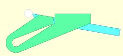
    And, lastly, what I am dreaming about is a parting tool holder along these lines:
    Spring Cut Off Evolution! An Easy to make design + the PLANS-winky.jpeg
    (white = item to be parted off, green = toolholder, blue = tool bit)
    so that the pivot is forward of the work piece and I have an unobstructed view of what I am parting off. What I have is a basic idea, what I need are the facts upon which final dimensions can be based.

  13. #9
    Supporting Member winkys workshop's Avatar
    Join Date
    Apr 2020
    Location
    Kentucky
    Posts
    161
    Thanks
    1
    Thanked 430 Times in 109 Posts

    winkys workshop's Tools
    That's a very cool idea and it might work great. You moved the point of flexing in front of the tool which would have similar effect as above I would think. Obviously a change in flex position is not the different between tool 1 and 2. I still feel that moving the point of pivot or flex is helps this type tool work better and yes, I think the first tool was close to not working and there is a slight difference between them. A few observation: The second tool works on smaller stock and or when the lathe is in back gear (very slow). If you are in the US I can ship you the first two if you want... you can keep them. One more idea I had was weld and extension on to the arm that flexes and add a weight. I think resonance is huge with any cutoff and this would change the frequency.

  14. #10
    Supporting Member NortonDommi's Avatar
    Join Date
    Jul 2014
    Location
    North Island, New Zealand.
    Posts
    990
    Thanks
    1,800
    Thanked 525 Times in 315 Posts

    NortonDommi's Tools
    Spring tools with the cutting edge behind the fulcrum point are a blessing on light shapers as well.
    When it comes to a lathe I am 100% behind the 'upside-down' tool,(if it can be done),for many operations. RH threading can be done away from the head, boring is easier as you can see what is happening on the backside and cutting off is a breeze.
    Nice job reviving an old tool Winky, they definitely work. One problem that many may not consider is the axial position of the cutting edge from the tool-post centerline which induces a rocking couple that I believe is a big problem on lightly built machines that lack rigidity.

Thread Information

Users Browsing this Thread

There are currently 1 users browsing this thread. (0 members and 1 guests)

Bookmarks

Posting Permissions

  • You may not post new threads
  • You may not post replies
  • You may not post attachments
  • You may not edit your posts
  •