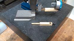
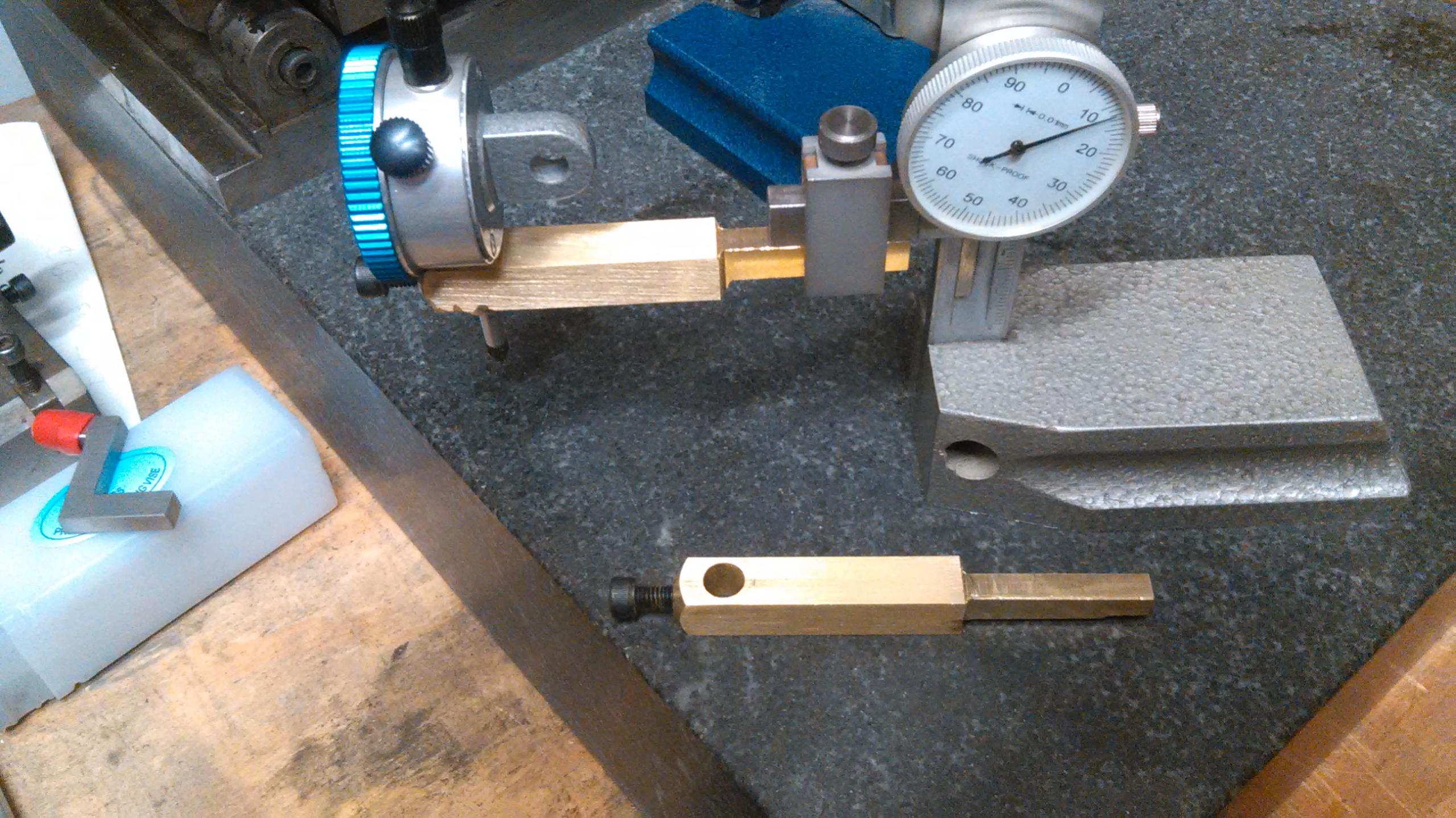
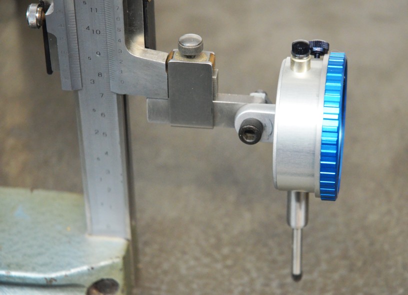
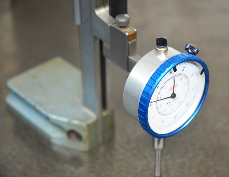
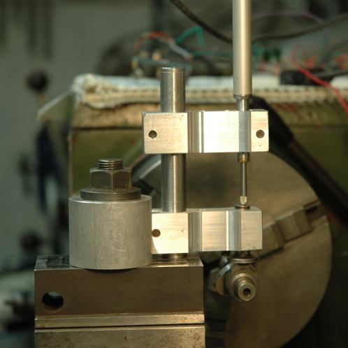
I always use the lug for mounting wherever possible. If there is no lug or other good reason to prevent its use then I use a split clamp to hold the instrument by the barrel, as in the following photos which show a clamp mounting, holding a linear encoder. Sometimes I fit a dial gauge when I don't need great accuracy or don't need to read by Laptop.
It would only be in exceptional cases that I would ever use a screw to clamp the barrel in a hole as you have done. There are 2 reasons for this.
1. It is the least kind method for the instrument, if tightened too much it will distort the barrel.
2. It is the least secure method. Unless the hole is a very good fit and reasonably long the gauge is likely to wobble about destroying accuracy. This imprecise fitting encourages over-tightening of the screw.
There are those who worry about the lack of precise vertical alignment, when using the lug, but these concerns are over exaggerated. Without much care it is easy to align the plunger to within say 0.5deg as a worst case. The effect of such misalignment is proportional to the cosine of the angular error. To put numbers to that, it means that over a movement range of 25mm the total error would be less than 1 micron for a 0.5 deg setup error. Or in other words 0.04 microns per 1mm. Way, way less than the resolution and accuracy of most any dial gauge, and also way less than the effect of minor temperature changes.
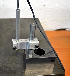

On the left the encoder is clamped for use on a surface plate. On the right it is mounted in place of a lathe toolpost for measuring camshaft profiles. The large hole in the block is a legacy of the block's previous use. just a nice heavy piece out of the scrap box, hardened and ground on the bottom and sides so ideal for its new use.
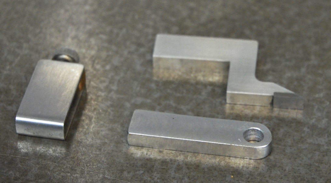
Here is another example of clamping on the shank that I posted a while back.
http://www.homemadetools.net/forum/p...5372#post81710
 LinkBack URL
 About LinkBacks


 Reply With Quote


Bookmarks