 LinkBack URL
 About LinkBacks
I take that back if you've attached the DI onto a freshly machined surface which hasn't yet been removed from the chuck. In which case this procedure would be necessary for each alignment check.


I take that back if you've attached the DI onto a freshly machined surface which hasn't yet been removed from the chuck. In which case this procedure would be necessary for each alignment check.


No it does not depend on the accuracy of the chuck or whatever mounting arrangement you use. The working end of the dial gauge rotates about the spin axis of the headstock, regardless of the structure between the lathe spindle and the dial gauge.Originally Posted by Bony

On the other hand, the method of using a precision bar to clock up on relies on how concentric the headstock centre is with the spin axis.
Toolmaker51 (Apr 26, 2019)


I'm sorry Tony, but despite the translation with Reverso i can't understand why if it's an un-centered chuck it can function, later I go to the workshop to try myself because without a good translation it's difficult for me.
When you describe the most common methods, we learn a good one when I was an apprentice which I use on a lathe when it's not at home, using a bar with a design like a bobbin mounted between centers and taking a light part of metal at each end it need just a measure with the caliper and a fast calculation for an horizontal alignment.
Out of subject commentary. ;-)
On some Schaublin system it's a good vertical and horizontal dead end which I'm now modify to put on another lathe and make some pictures for the forum if it's some interest in that adaptation.
I shall try to explain in a clearer fashion. If that does not work then maybe another forum member with better powers of explanation can jump in and take over. Maybe Rick or Marv could make it clearer.
1st try.
The dial gauge is fixed to a support bracket, the connection point between the bracket and gauge is offset from the spindle axis. The connection point will travel on a true circle centred on the spindle axis. So if the support bracket is fitted to a chuck with some runout it does not matter. The bracket shape and dimensions are purely arbitrary and only have to hold the gauge plunger against the tailstock centre. The ball on the end of the gauge plunger does not even have to be dead centre because its travel will still be on a circle centred on the headstock spin axis.
If you mount an indicator on the tool post to check the concentricity of a bar, the point of the indicator does not have to be dead centred. There may be an error in the amount of runout that is indicated but it will still tell you if there is runout or not. The same thing applies to the tailstock centering method that I described. Unless the offset of an indicator is large the error in the runout magnitude will minimal anyway, but it will still indicate if you are aligned or not.
2nd try.
Image that you have a chuck or face plate on a lathe that has been fitted such that it has a lot of offset. Run the lathe and it will be obvious that the outside is NOT concentric with the spin axis. Now image that you paint a small dot on the outside of the chuck or face plate. Now run the lathe. You will see that the dot describes a circle centred on the spindle axis regardless of the fact that the chuck as a whole is eccentric.
Apply that reasoning to my gadget. Any given point on the chuck-bracket-gauge assembly will be rotating true to the spin axis, and that is all that is required.
That is it, I have no other ammunition with which to convince you. I understand that technical explanations can be difficult in a language other than one's mother tongue.
Okapi (Apr 26, 2019), olderdan (Apr 25, 2019), Toolmaker51 (Apr 26, 2019)

Tony, surely your video on the laser centre finder depicts the same principals, anything rigidly mounted can only rotate about the true axis of the lathe or mill mandrel.
Toolmaker51 (Apr 26, 2019)
Alan,
Yes exactly.
Thanks Tony, then I understand what you mean, it's clear than in every manner you fix the dial gauge on the nose of the lathe it will make a perfect center from this point, looking your video more concentrated was the best way, at the first time when not perfectly in the subject I suppose you have a rotating piece on an arbor and not rotate the chuck because i've not take the time to heard your commentary…
Sometime swhen you're translating, you go totally in the wrong way and it was what I've made.
Toolmaker51 (Apr 26, 2019)
It's very clear now, thanks. I too mistakenly thought the DI rotated about the chucked workpiece, whereas it's actually fixed onto the workpiece and rotates about the spindle axis. Should have looked at the excellent video. I'm annoyed with myself.
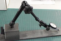
Tony has a very rigid & compact assembly to hold the indicator. But just a word of caution if you were thinking to replicate the rotating indicator action with a typical mag stand. All bets are off as gravity can act on the extended arms & joints. The dial will read differently upright than inverted & depending on the extended arm, even laterally side to side. I've attached a RK video link below.
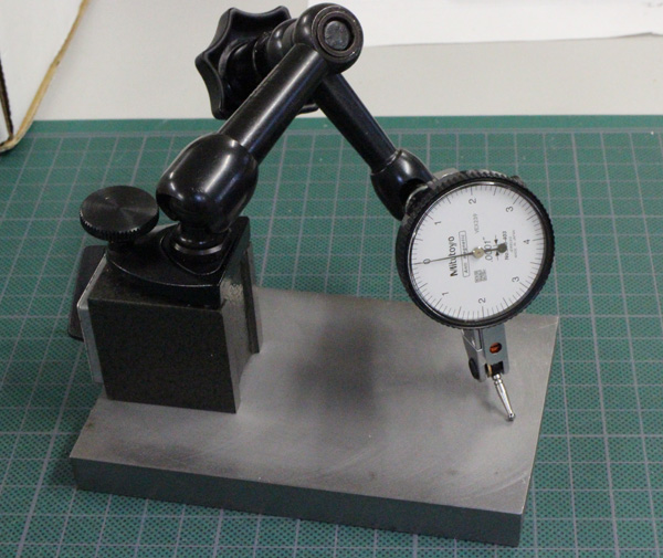
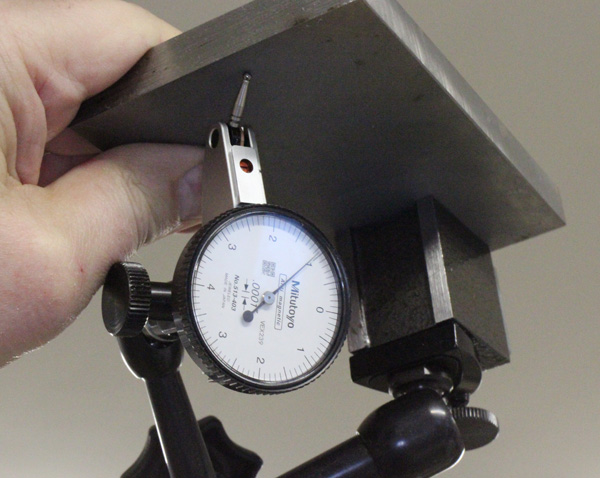
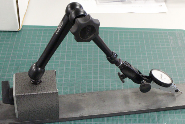
I crudely mimicked this with my equipment & got the following on a mini mag holder vs typical mag holder. Your mileage may vary.
Noga 6"? Mini + Mitutoyo 0.0001" DTI: Level reference = 0.0000", 90-deg = 0.0005 - 0.0008", 180-deg (inverted) = .0011
Noga 12"? + Mitutoyo 0.001" DTI: Level reference= 0.000", 90-deg = .0042", 180-deg = .0055" (suspect a smidge more because it didn't return to zero & there might be some flex in my bar).
Okapi (May 6, 2019), tonyfoale (May 6, 2019), Toolmaker51 (May 6, 2019)
Yes, this is clear that the gravity can interfere with a measurement, with Tony's methodology, the use of the more rigid and more lighter the system is and better it is, with low quality arms especially you can have some variations between the different positions, the system you show is not a good idea for measurements on a rotation axis, for having made some tests on the horizontal milling machine those articulated arms can vary from % on a 180° horizontal position due to the construction with heavy parts.
There are currently 1 users browsing this thread. (0 members and 1 guests)
 Posting Permissions

 Reply With Quote
Bookmarks