
 LinkBack URL
 About LinkBacks


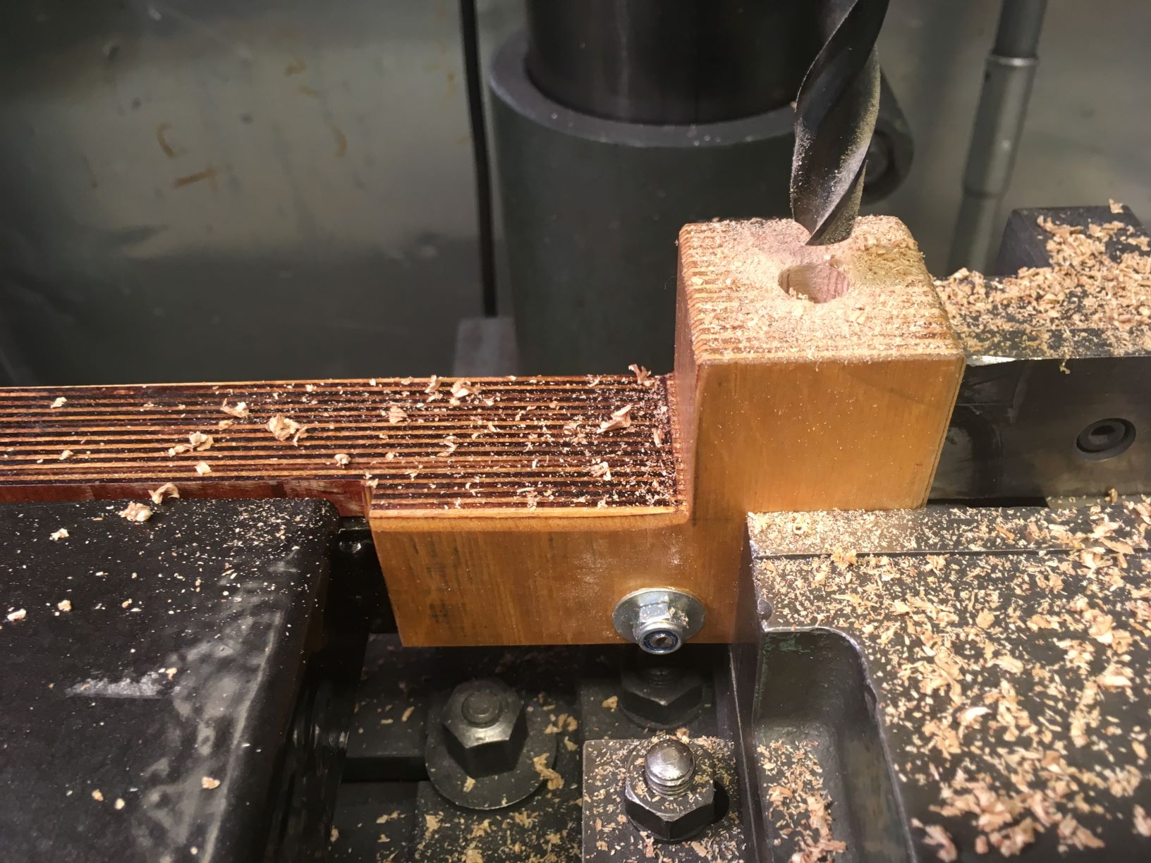
Whilst rebuilding/ aligning the lathe, now's the time for fitting the adjustable feet for the entire stand.
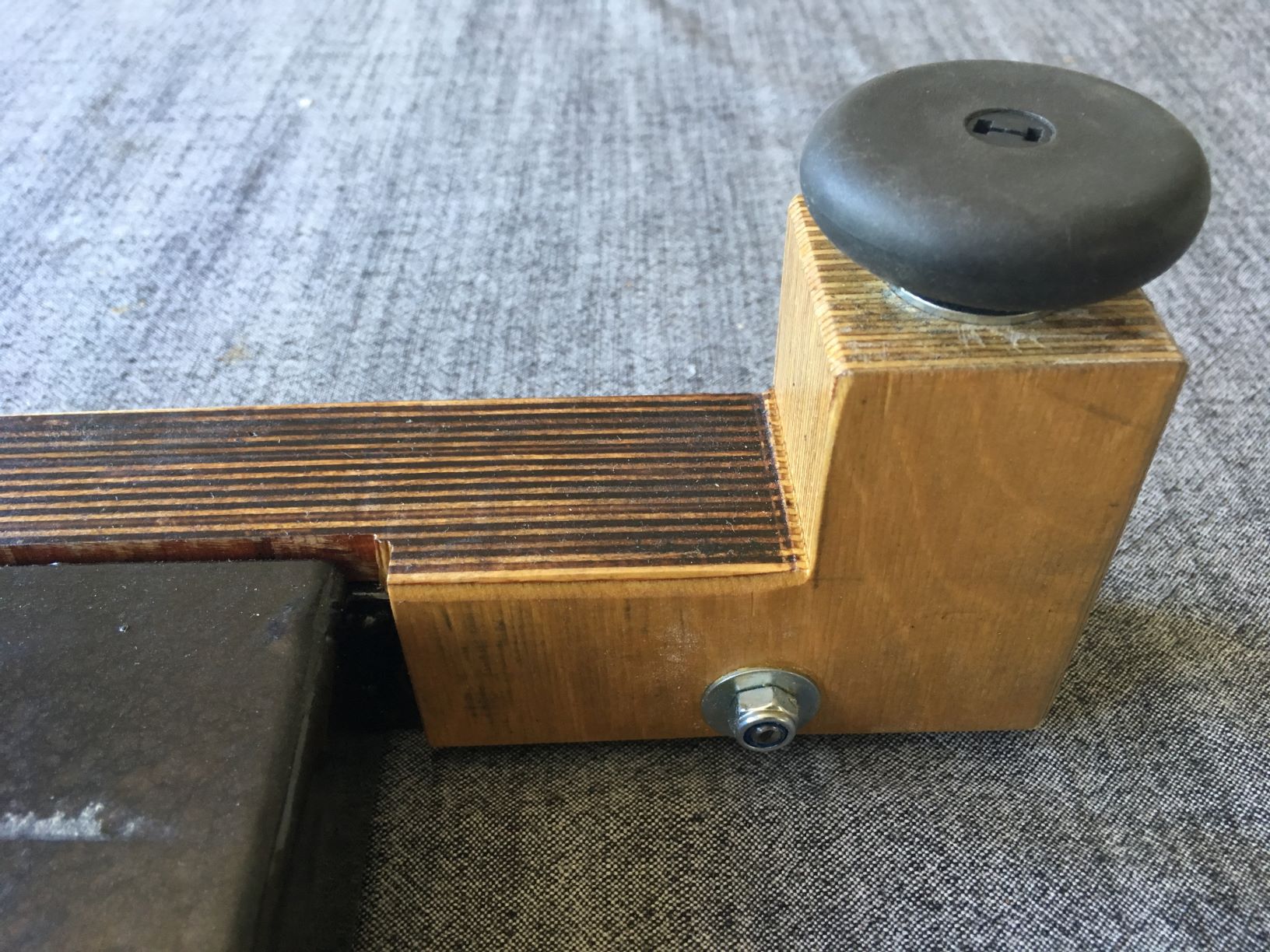
4 pieces of 48 mm dia, former office chair rubber knobs, 4 reused M8 threaded inserts and a 12 mm drill:

These will admit adjusting the 4 legs of the entire lathe/stand on just about any surface,
without disturbing the bed's flatness - as the RHS beam provides (almost) total rigidity.
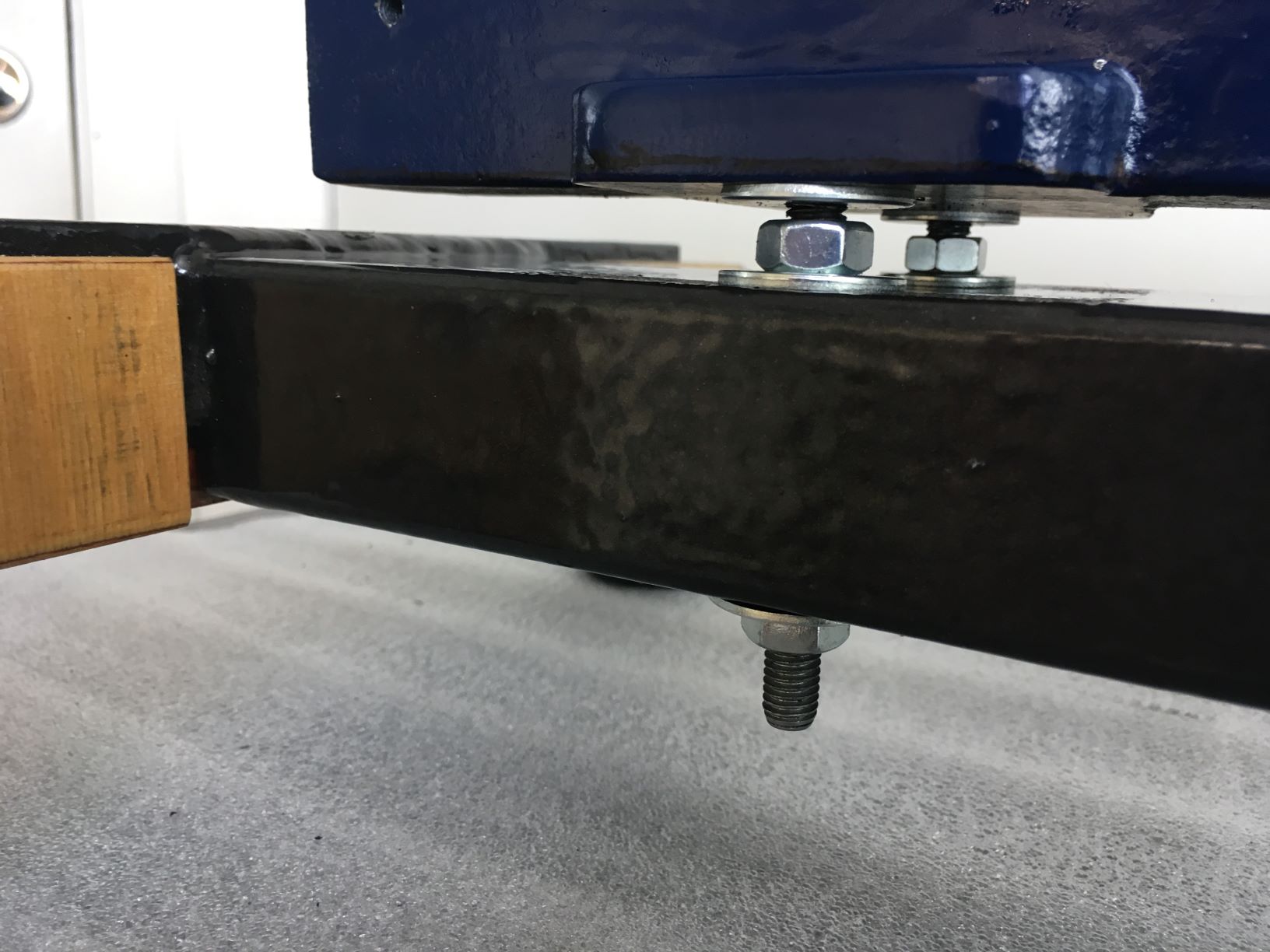
Thus the lathe's bed must be rigidly fastened to the beam, but also allow for relative and easy adjustments:
4 pieces of M8 all-thread were cut, and 15 mm of one end of each were turned down and threaded M6,
put into the bed, now resting upside down diagonally on my surface plate.
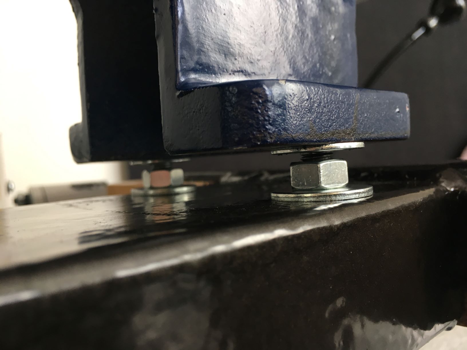
Fitted the all-threads pointing upwards, adding washers and nuts, placing pieces of 10 mm HSS blanks as temporal spacers.
Then the beam/ foot was lowered, the final washers and nuts put on, and adjustments started.
My point in having it upside down would hopefully provide bed flatness & stress-free initial mounting,
as the 6 kg beam "just floats" on the HSS pieces whilst I tighten the nuts equally, just releasing the spacers.
If done the ordinary way, perhaps warp could be introduced by the lathe's own weight affecting the beam unevenly.
Headstock (left) and tailstock (right)

When turned over, bed now measures straight and unwarped to 0.05 deg (I'm waiting for a machinist's level in transit).
The bed top is also parallel (i.e. equidistant) to the beam, both length- and crosswise.
I'm considering helping the headstock bolts with a 4 x 4" 10 mm aluminum plate for weight distribution - undecided yet.
Now alignments, measurements and tweaks will commence for the headstock, saddle, crosslide and tailstock in rotation.
To be continued...
Thoughts, comments and suggestions on the above welcome!


 Reply With Quote

Bookmarks