Free 186 More Best Homemade Tools eBook:  
New: 300+ fresh build posts/day from 275 forums → BuildThreads.com

User Tag List

Results 11 to 14 of 14

Thread: The Universal Marking Gauge

Threaded View

  1. #1
    Supporting Member Dimitris Polychronis's Avatar
    Join Date
    Nov 2018
    Location
    Athens-Greece
    Posts
    157
    Thanks
    154
    Thanked 337 Times in 82 Posts

    Dimitris Polychronis's Tools

    The Universal Marking Gauge

    Hello,

    Two years ago, I started this project at a friend's request; I thought also that it would be a nice project for my YT channel, but tragically, all the footage were lost due to computer failure, (these are the consequences of not keeping back up), but anyway. So, what I'm about to show you are pictures from the finished parts and their assembly.

    Now, my friend asked me to make one of these classic woodworking marking gauges out of brass; so I did a bit of research in order to get an idea of their dimensions and features. Once this was done, I decided that it would be best to use steel instead of brass. I started with a simple drawing and as I went along other ideas were coming as well. But let's look at these one at a time.

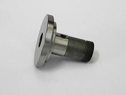
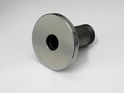
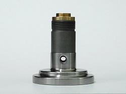
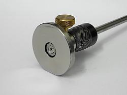
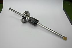
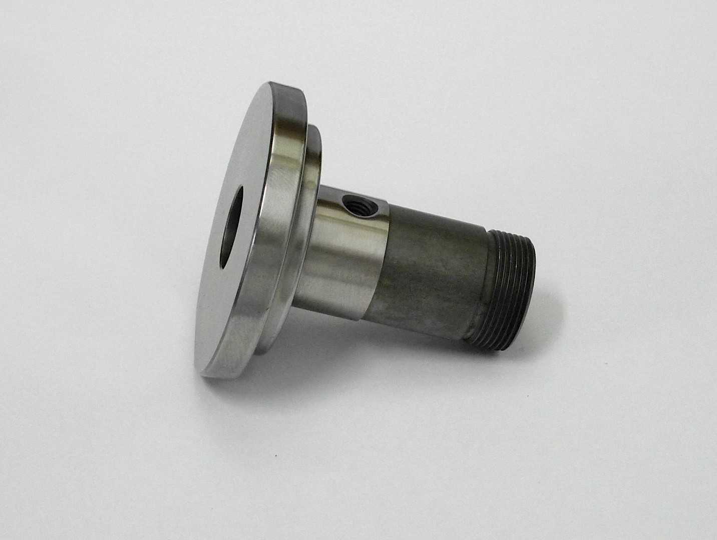
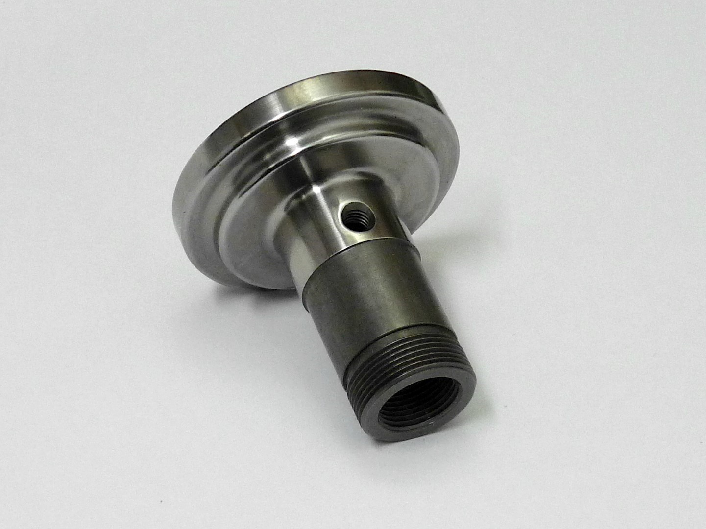
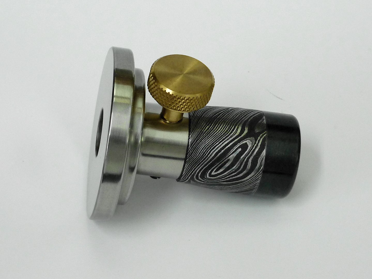
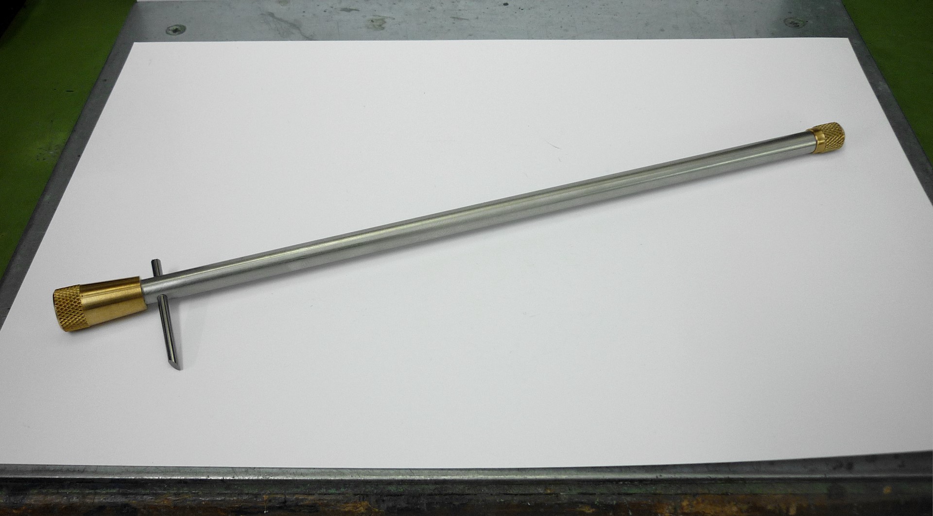
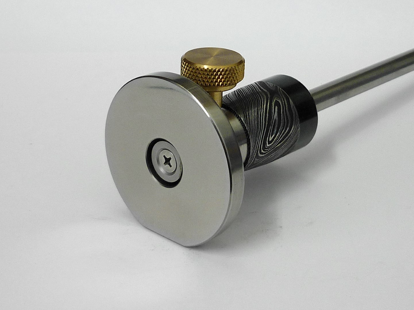
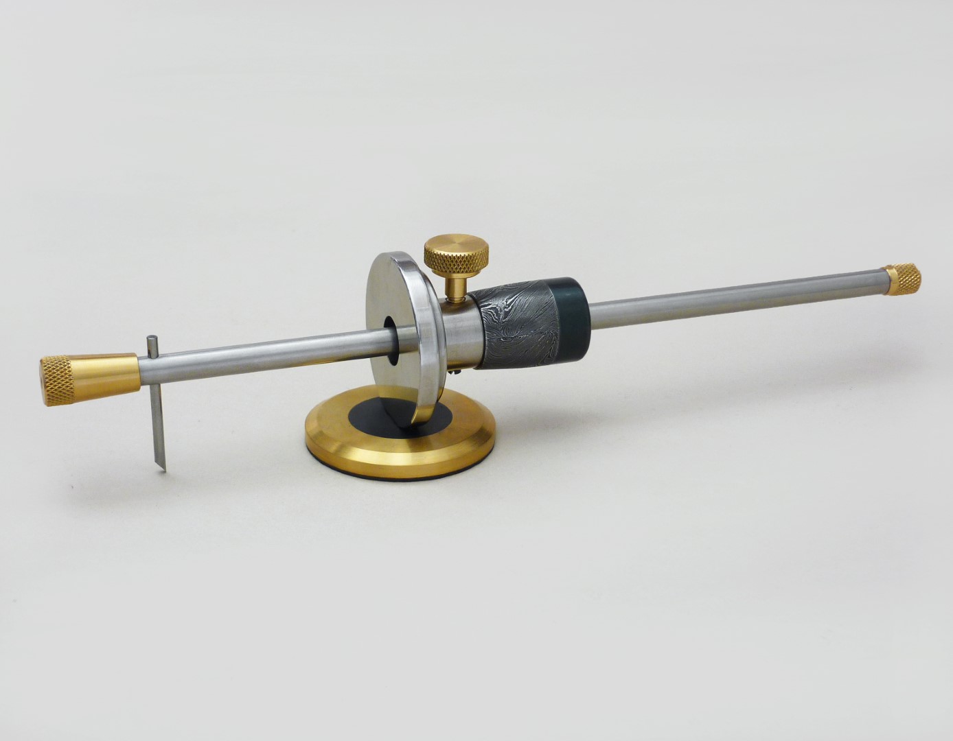
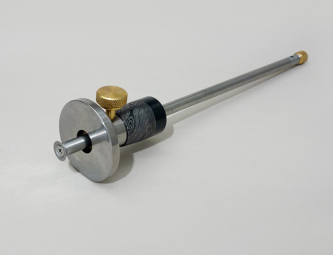
    The body of the gauge is made from free cutting steel and it is case hardened (Nitriding). Now, the idea of making this tool from steel and to be hardened was not only to serve for marking wood, but for steel as well.

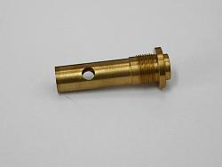
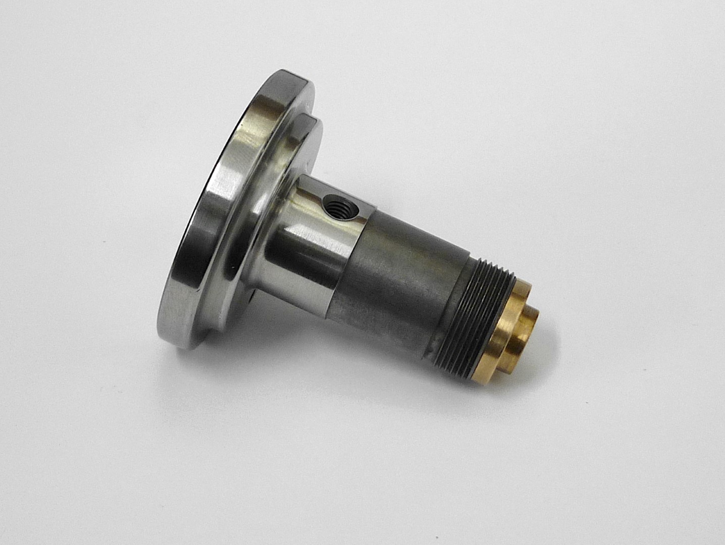
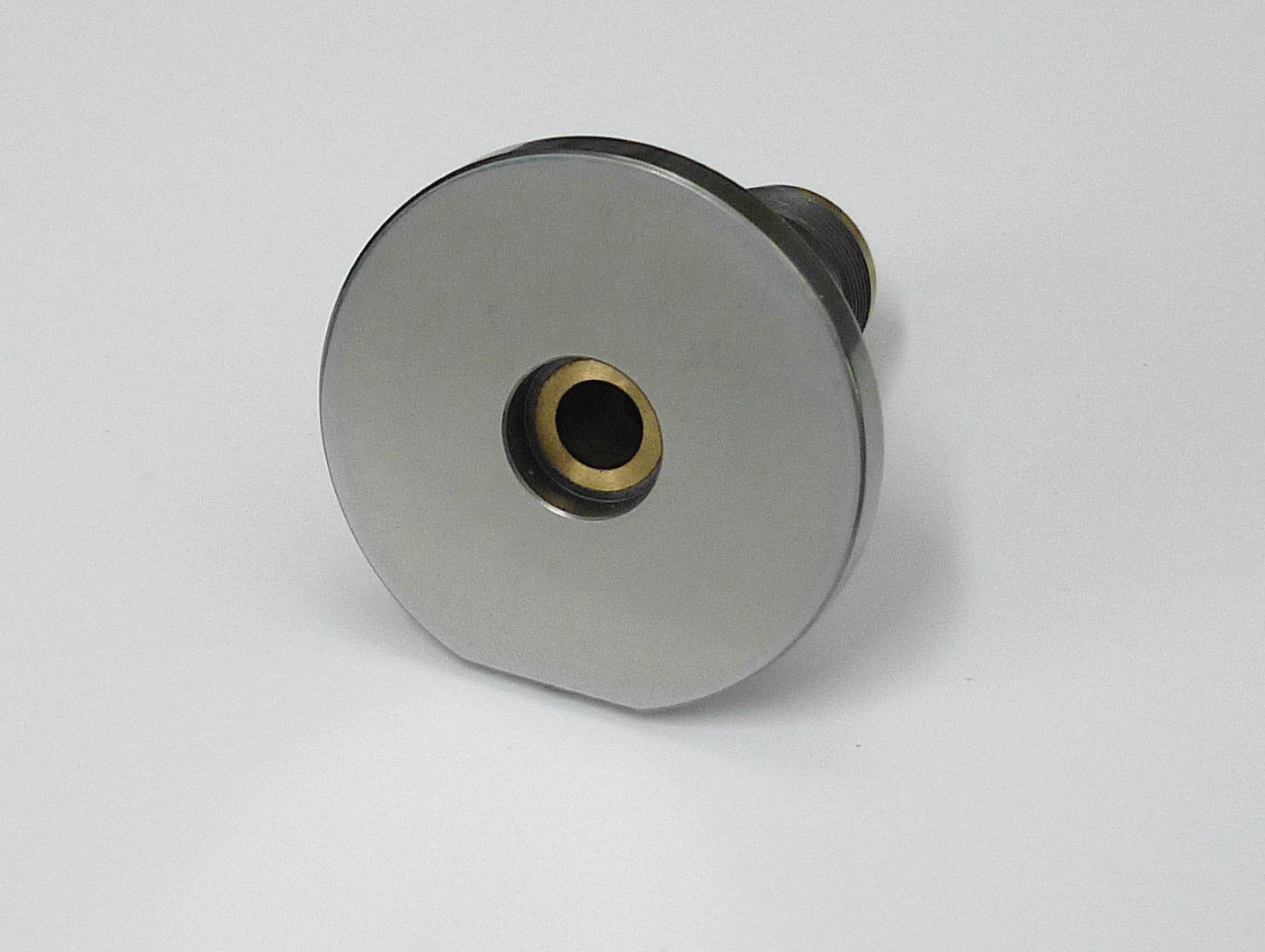
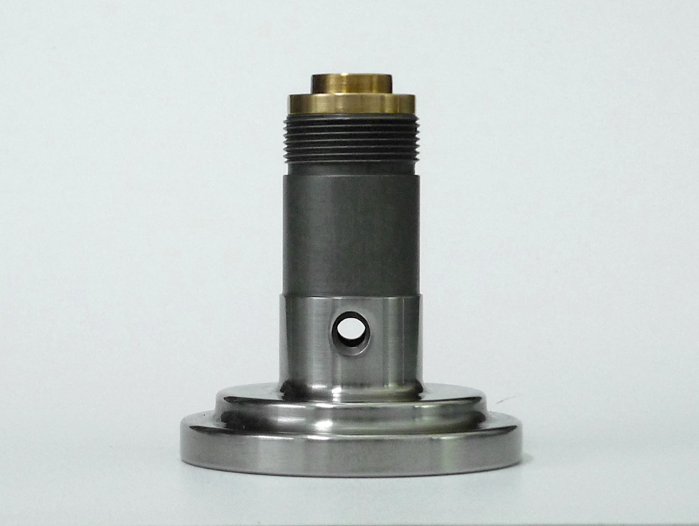
    The length of the body measures 50mm, the diameter at the thinnest section is 20mm and at the face is 50 mm. At the periphery of the face there is a flat (it is actually the bottom of the face) which stops the body from rolling.

    Click image for larger version. 

Name:	P1160674.JPG 
Views:	250 
Size:	235.7 KB 
ID:	40389 Click image for larger version. 

Name:	P1160675.JPG 
Views:	236 
Size:	217.8 KB 
ID:	40390 Click image for larger version. 

Name:	P1160676.JPG 
Views:	269 
Size:	254.9 KB 
ID:	40391

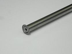
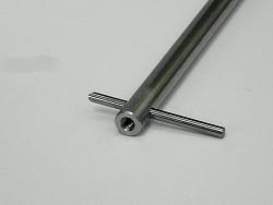
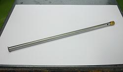
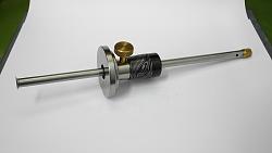
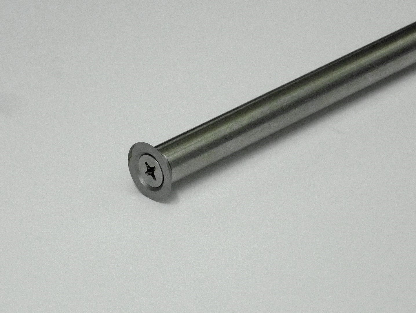
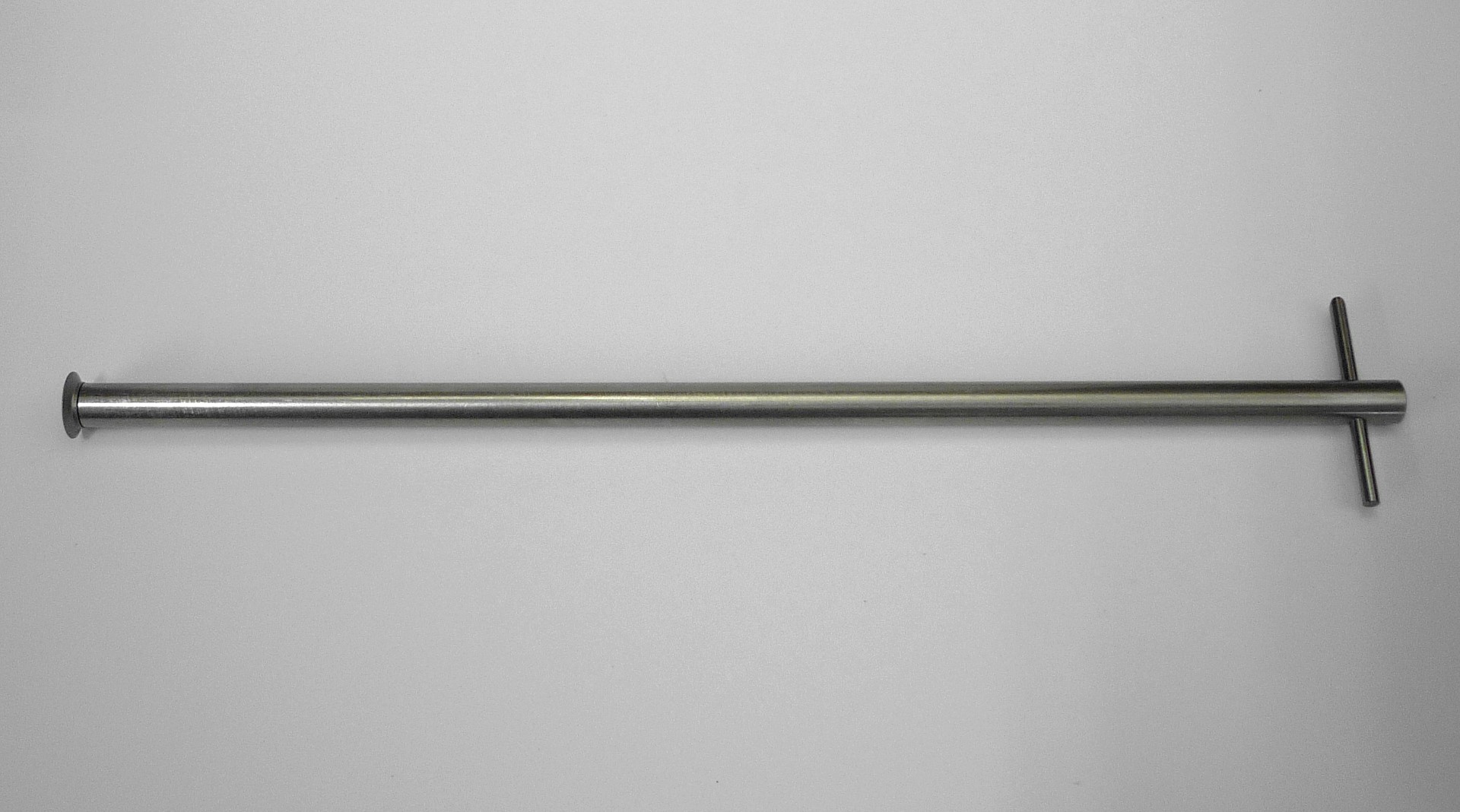
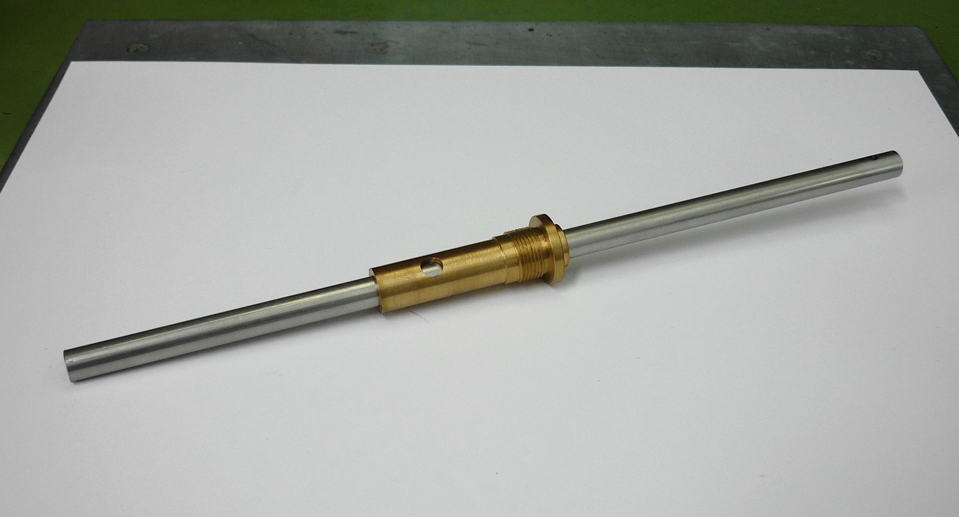
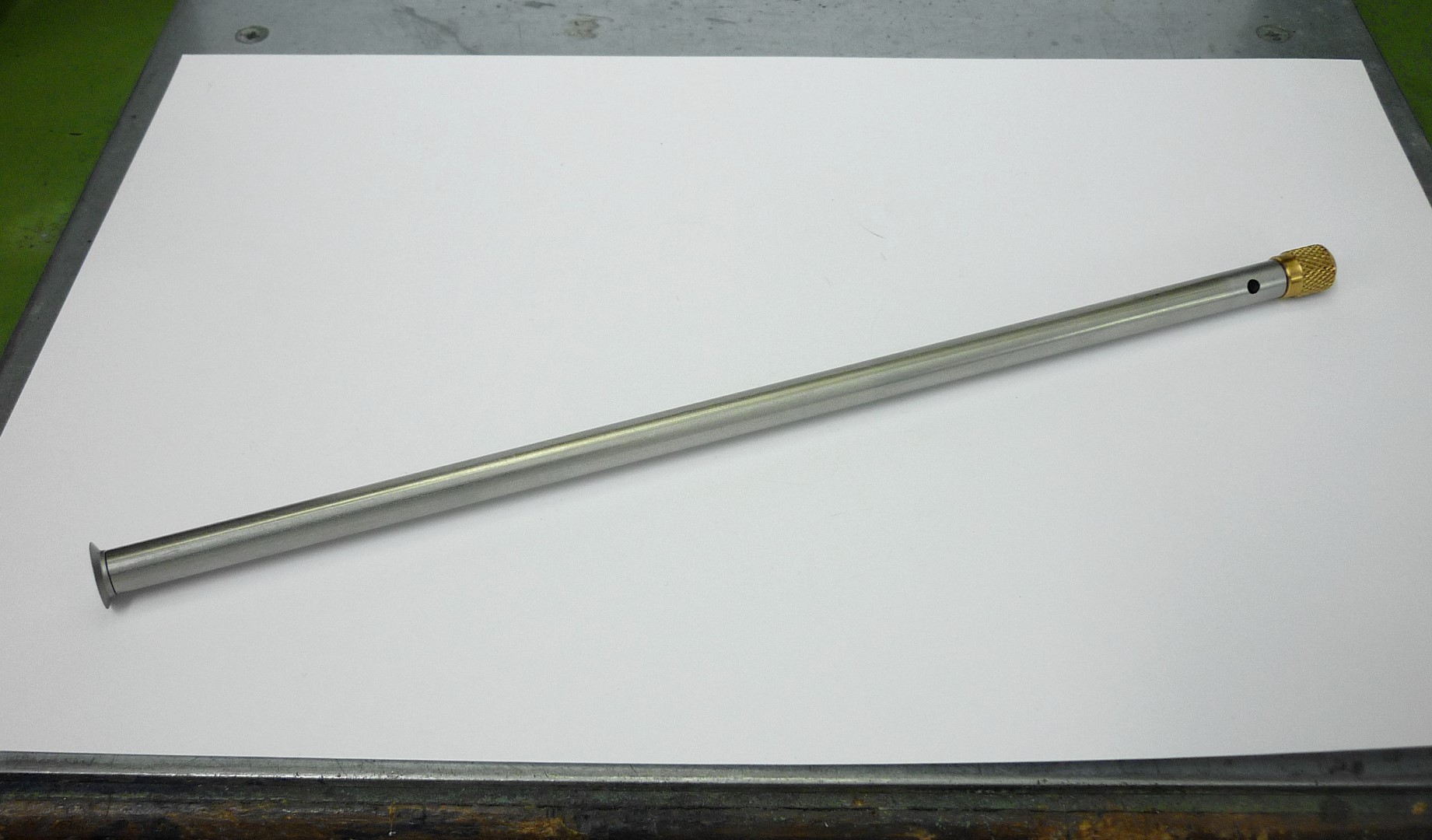
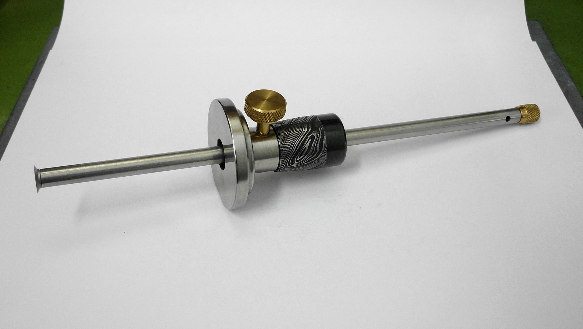
    For the shaft of the gauge I used a stainless steel 8mm in diameter x 70cm long shaft used in pneumatic spearguns; the actual diameter shown by the micrometer was 7.99mm, which was perfect for what I needed it for.

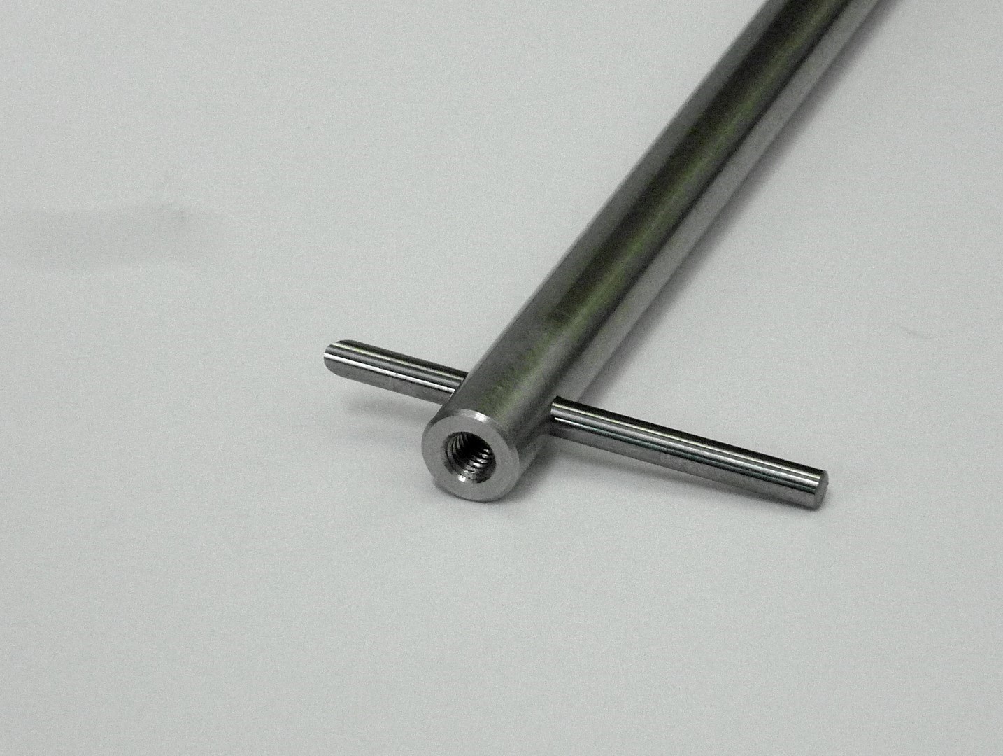
    The shaft threaded M4 on both ends, one end accepts the wheel cutter and on the other there is a cross hole 3mm in diameter which accepts a 3mm carbide rod. The total length of the shaft is 235mm.

    Click image for larger version. 

Name:	P1160678.JPG 
Views:	258 
Size:	333.5 KB 
ID:	40392 Click image for larger version. 

Name:	P1160679.JPG 
Views:	249 
Size:	343.2 KB 
ID:	40393 Click image for larger version. 

Name:	P1160680.JPG 
Views:	255 
Size:	352.9 KB 
ID:	40394

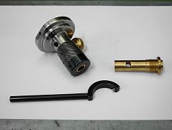
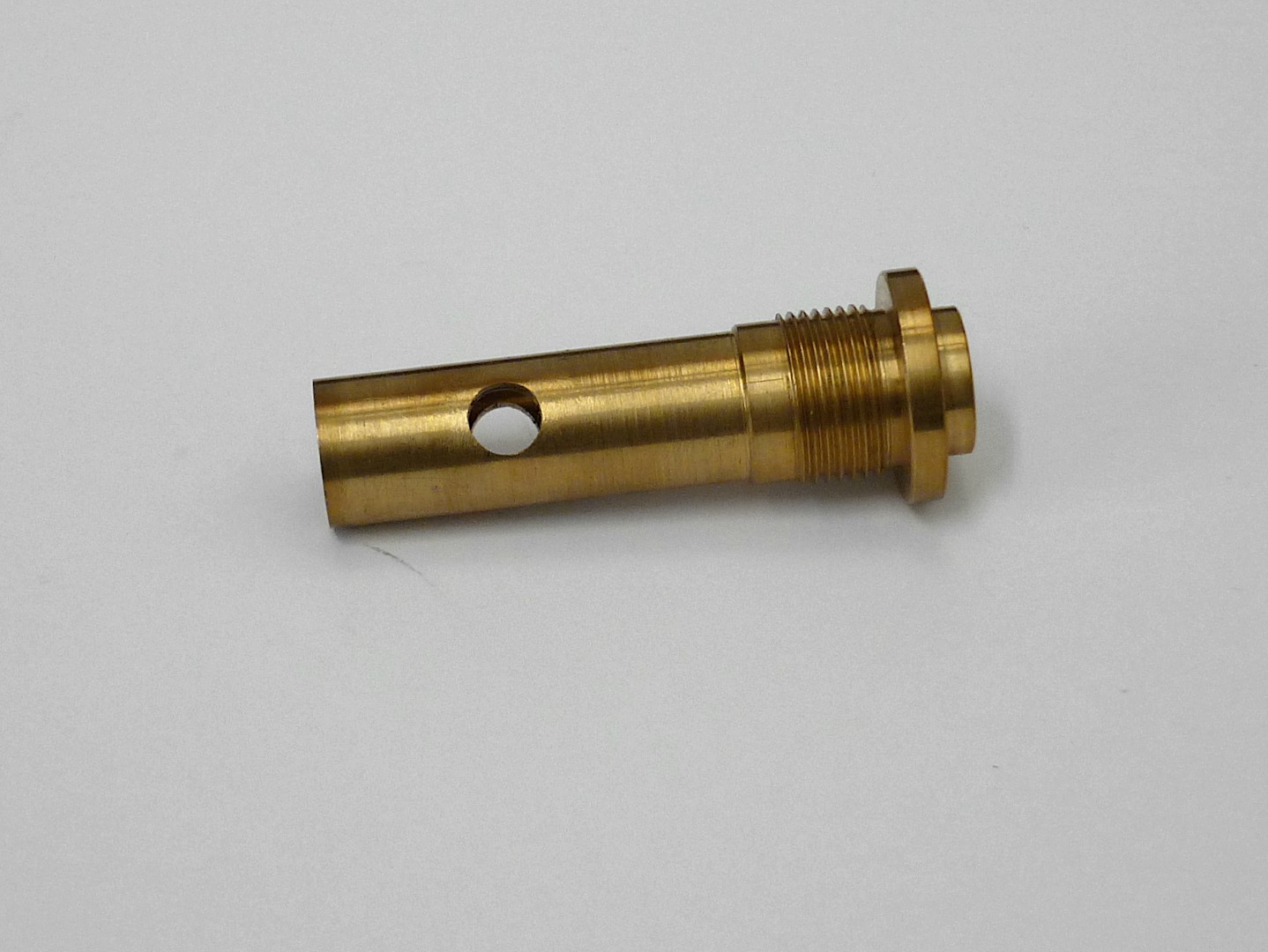
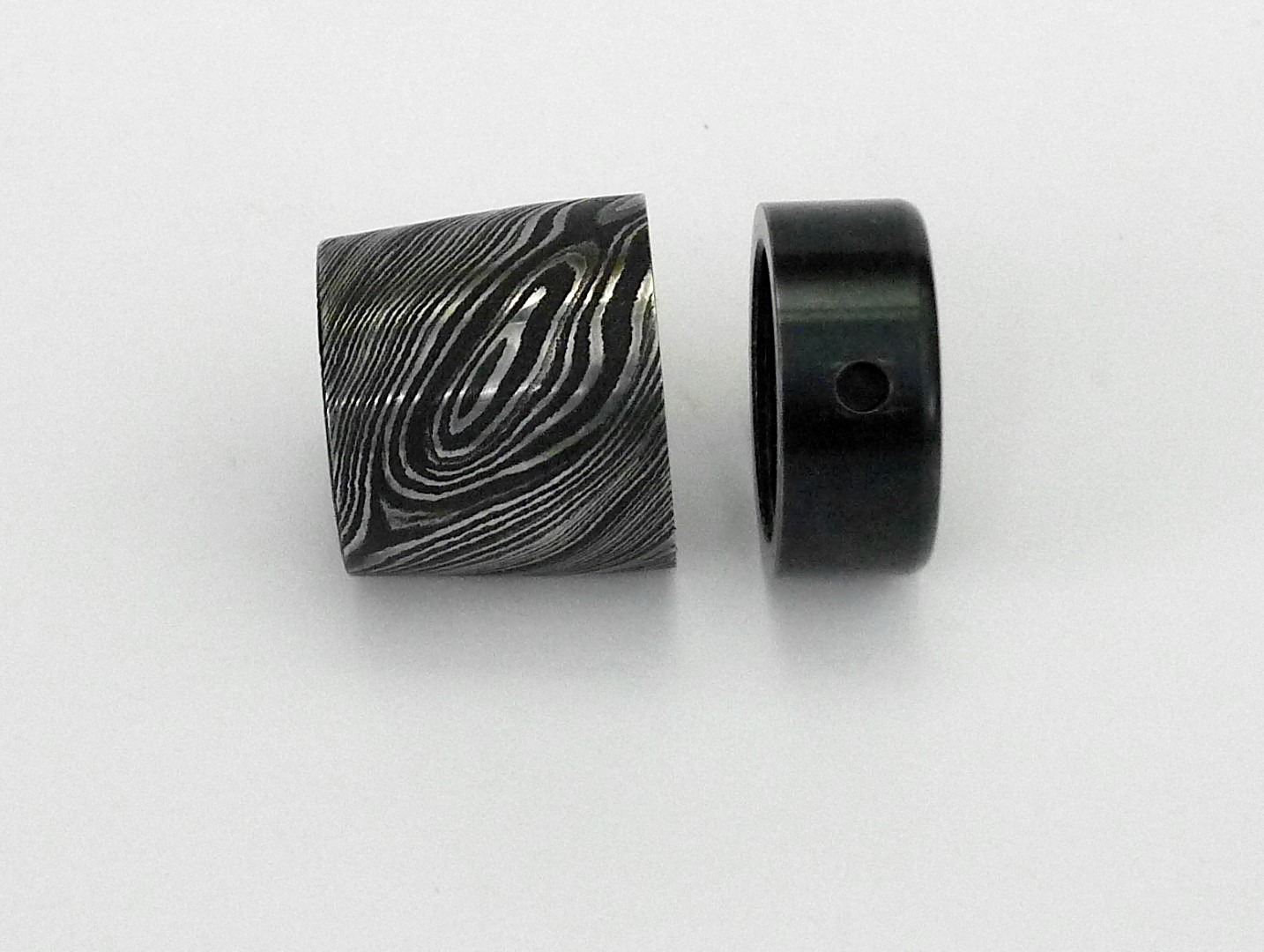
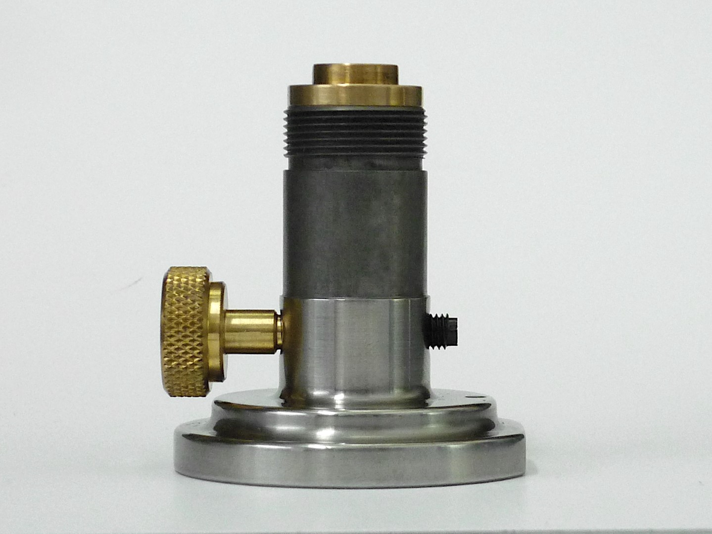
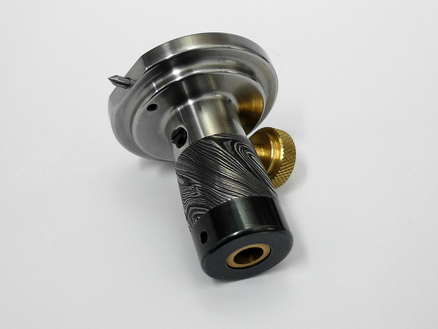
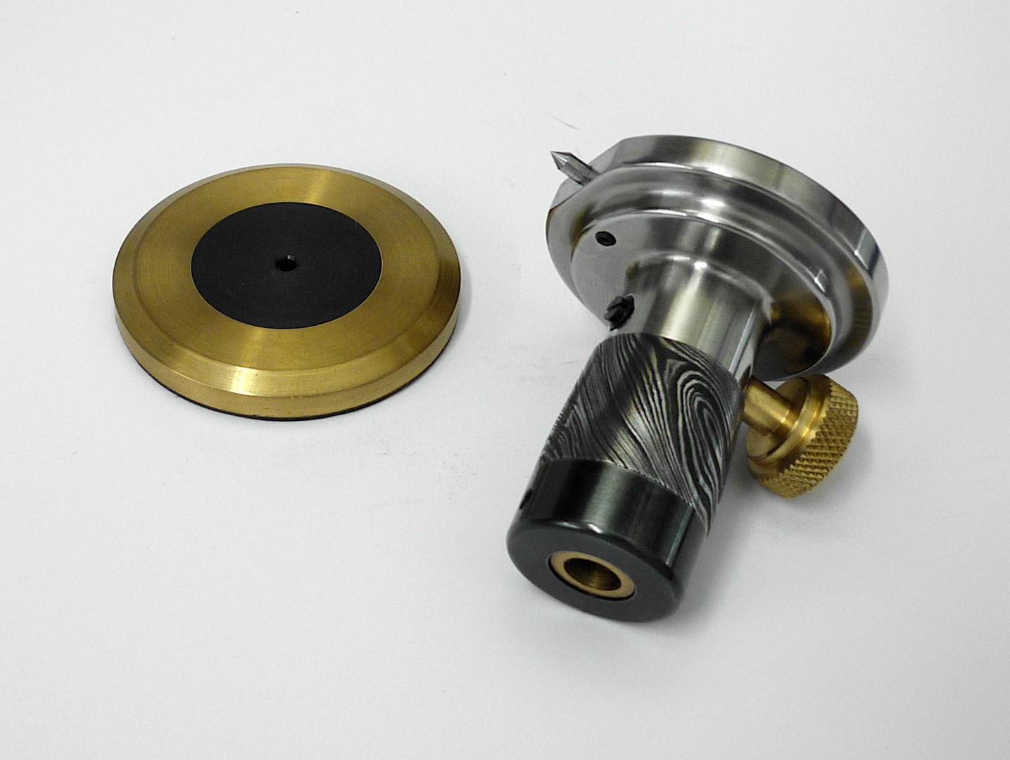
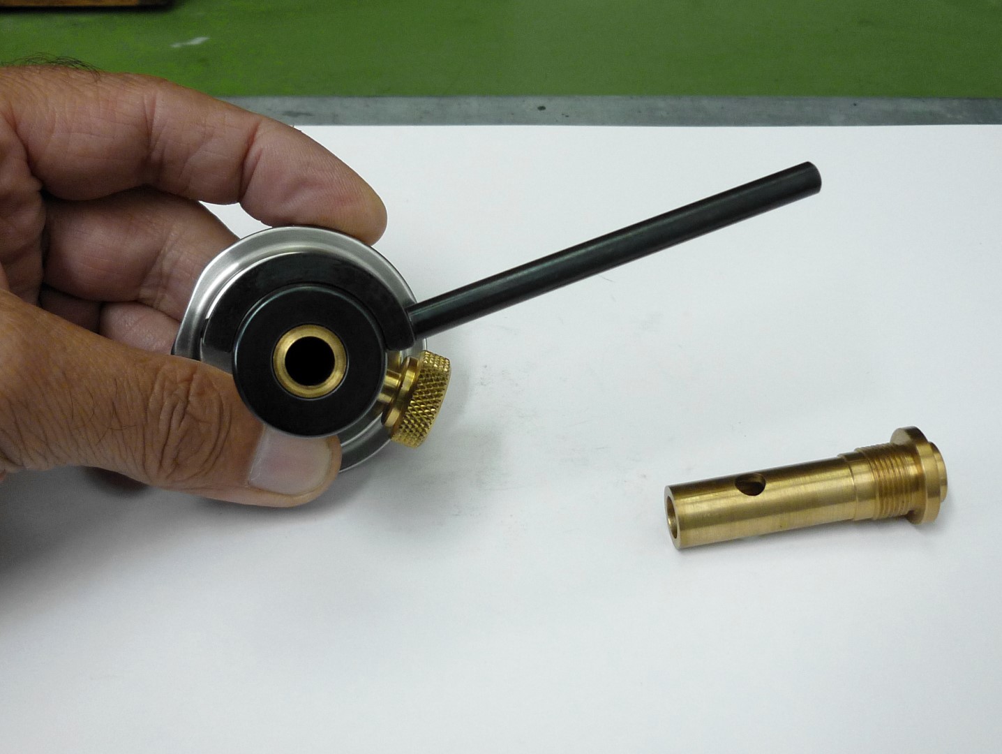
    Now the body of the gauge is a 4 part assembly; the main body, a threaded sleeve that supports the shaft, an outside taper ring and a threaded cup which both act as the handle.

    The sleeve is threaded 14x1mm and its bore reamed to 8mm; it’s made from phosphor bronze.

    Click image for larger version. 

Name:	P1160681.JPG 
Views:	241 
Size:	248.9 KB 
ID:	40395 Click image for larger version. 

Name:	P1160682.JPG 
Views:	228 
Size:	341.6 KB 
ID:	40396 Click image for larger version. 

Name:	P1160684.JPG 
Views:	221 
Size:	245.4 KB 
ID:	40397 Click image for larger version. 

Name:	P1160685.JPG 
Views:	237 
Size:	257.1 KB 
ID:	40398

    The outside taper ring is made from Damascus steel and the threaded cup from Calmax steel which has a small hole for a key to tighten it and it’s oxidized to add contrast.

    Click image for larger version. 

Name:	P1160686.JPG 
Views:	252 
Size:	279.6 KB 
ID:	40399

    One of the body’s features is that right beneath the knurled brass thumb screw there is a plastic set screw; by adjusting this screw I can control the friction applied on the shaft (the set screw feature was copied from the well-known Tite-Mark marking gauge).

    Click image for larger version. 

Name:	P1160690.JPG 
Views:	243 
Size:	190.4 KB 
ID:	40400 Click image for larger version. 

Name:	P1160691.JPG 
Views:	239 
Size:	231.7 KB 
ID:	40401 Click image for larger version. 

Name:	P1160699.JPG 
Views:	256 
Size:	263.1 KB 
ID:	40402

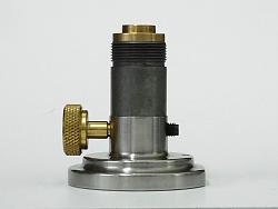
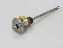
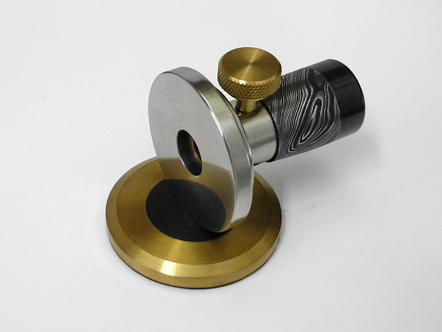
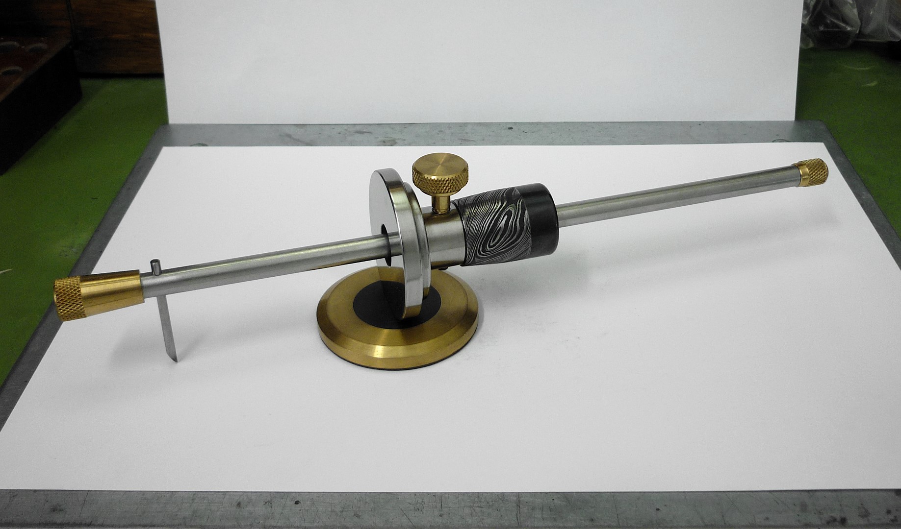
    Another feature of the gauge is that it can be converted to a compass for marking circles and arcs. This can be done by inserting a carbide pointing tip to the hole that is located on the flat surface at the down end of the round face.

    Click image for larger version. 

Name:	P1160700.JPG 
Views:	240 
Size:	218.4 KB 
ID:	40403

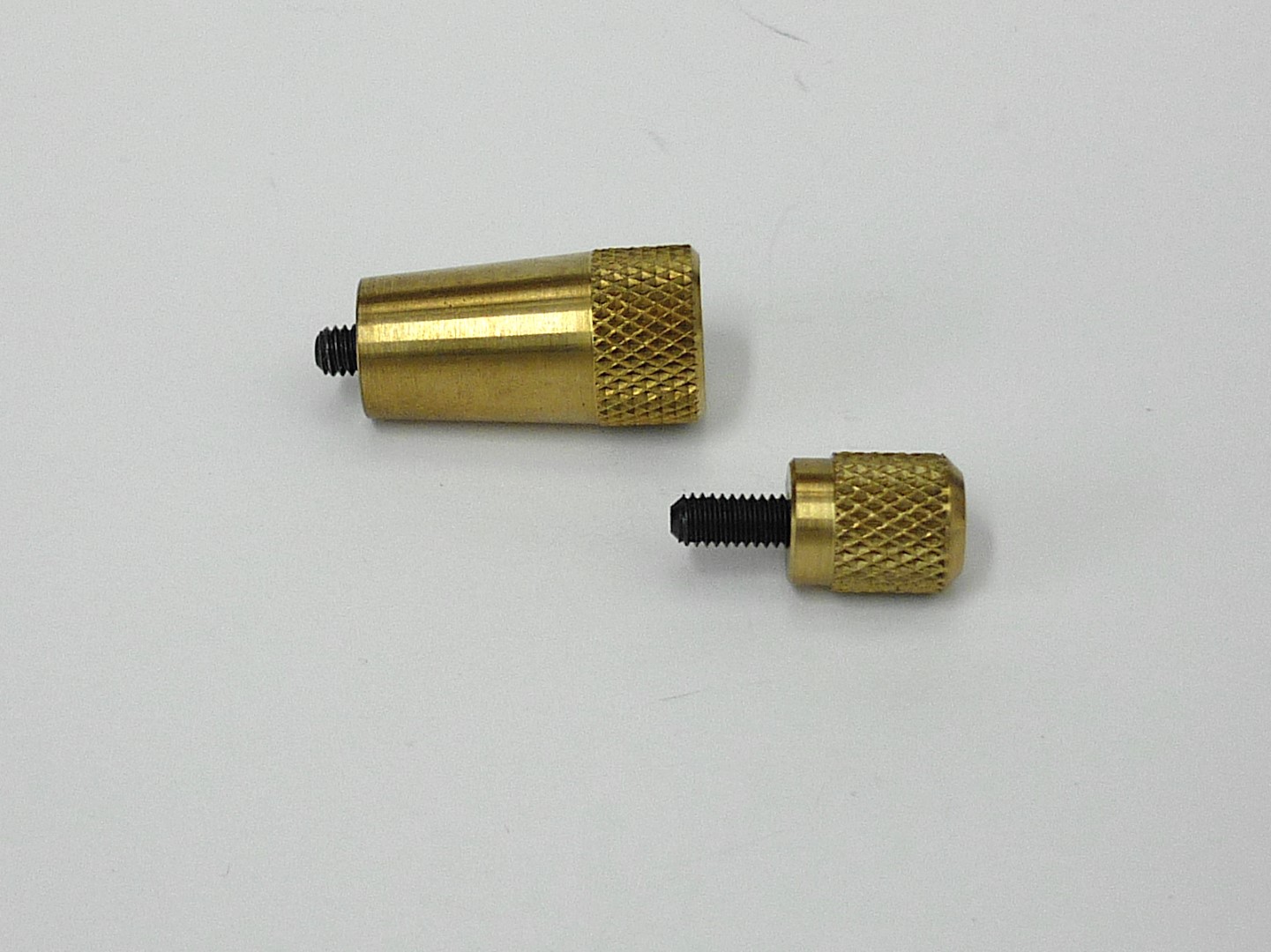
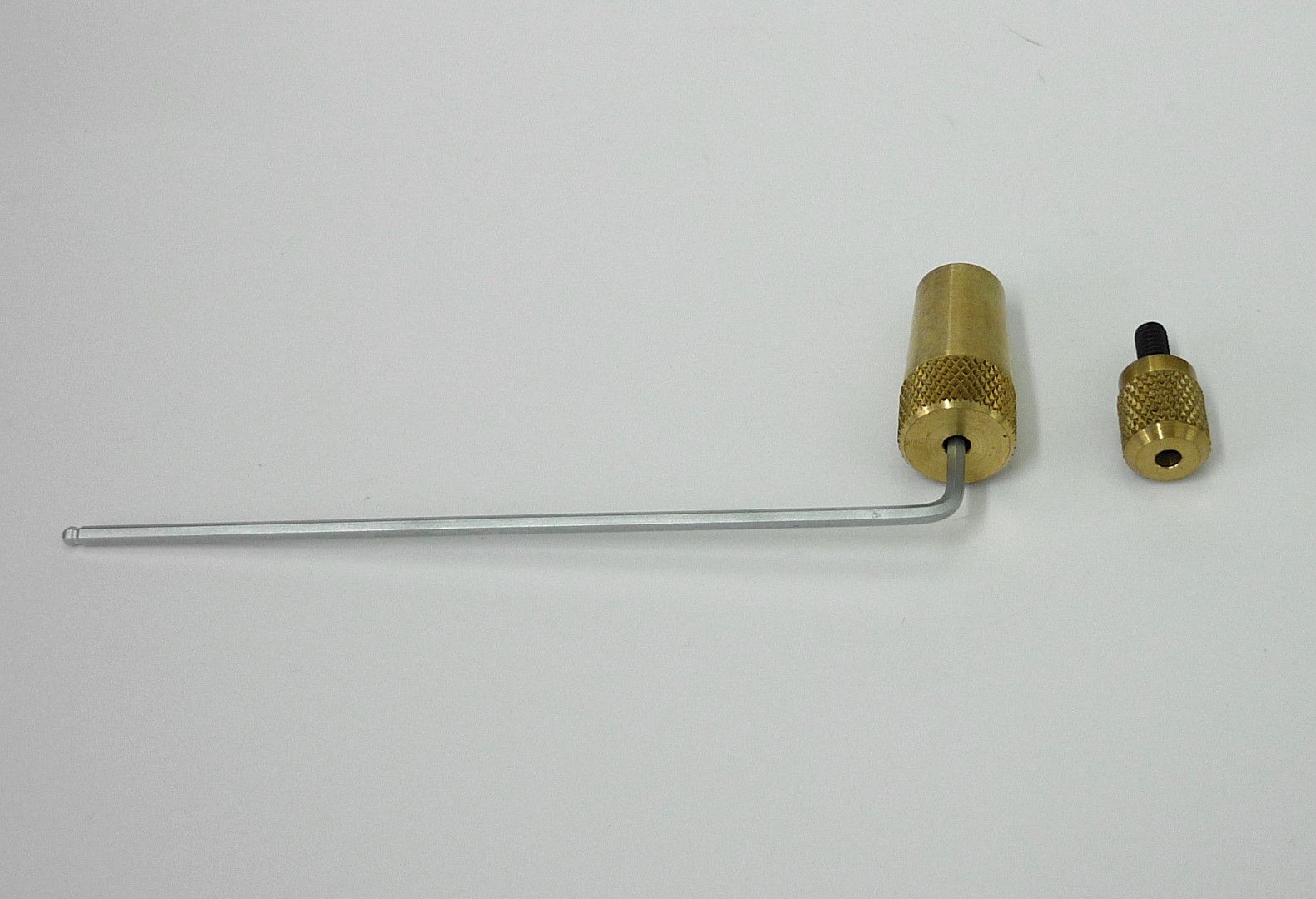
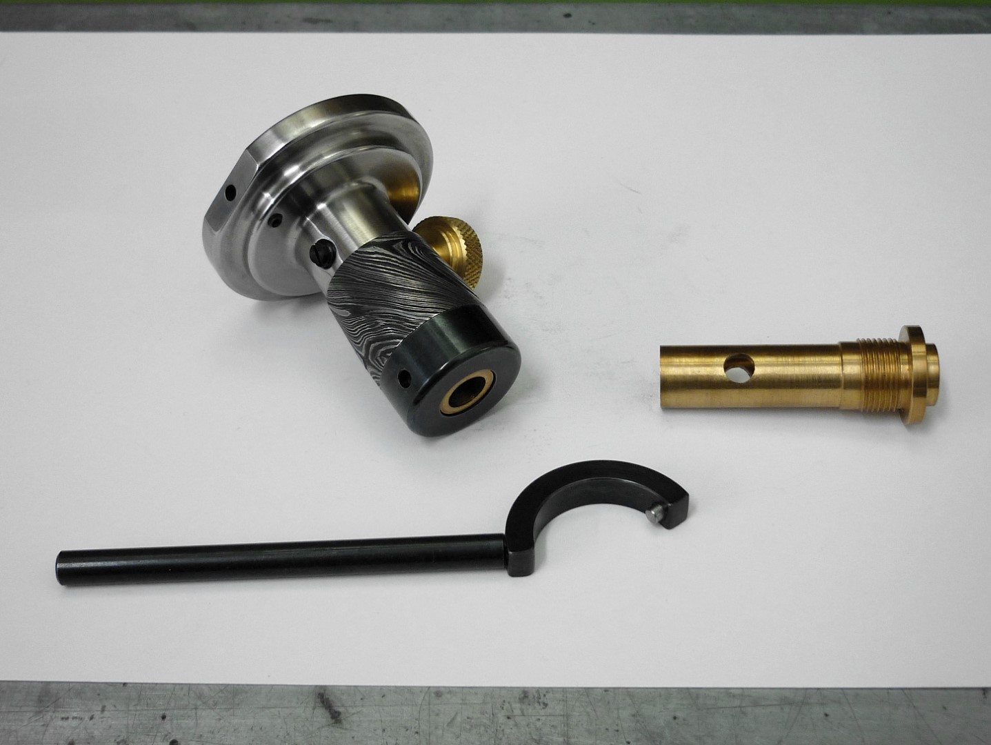
    I also made two brass nuts which both have an M4 set screw secured with Loctite. The short one is for keeping the shaft from slipping out from the body and the longest acts both for locking the carbide marking tip and as a handle when the gauge will be used for marking long lines or circles and arcs.

    Click image for larger version. 

Name:	P1160703.JPG 
Views:	243 
Size:	272.6 KB 
ID:	40404 Click image for larger version. 

Name:	P1160704.JPG 
Views:	243 
Size:	298.8 KB 
ID:	40405 Click image for larger version. 

Name:	P1160705.JPG 
Views:	238 
Size:	323.5 KB 
ID:	40406

    Although finger tightness on these two offers good grip, I can always use an Allen key for more secure grip.

    Click image for larger version. 

Name:	P1160706.JPG 
Views:	247 
Size:	262.7 KB 
ID:	40407

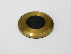
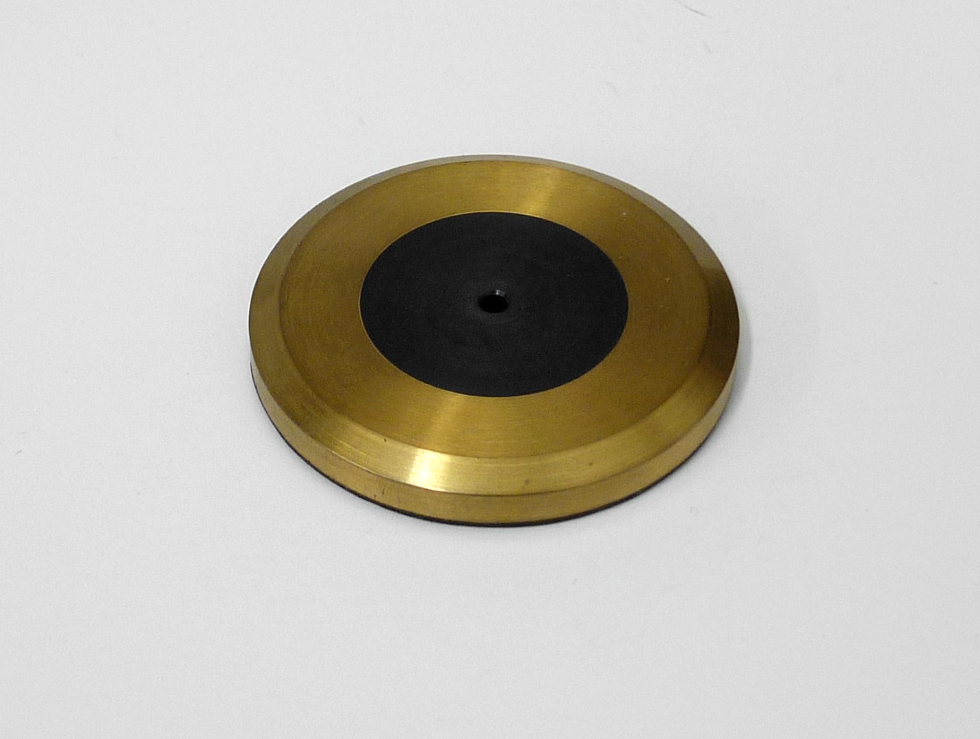
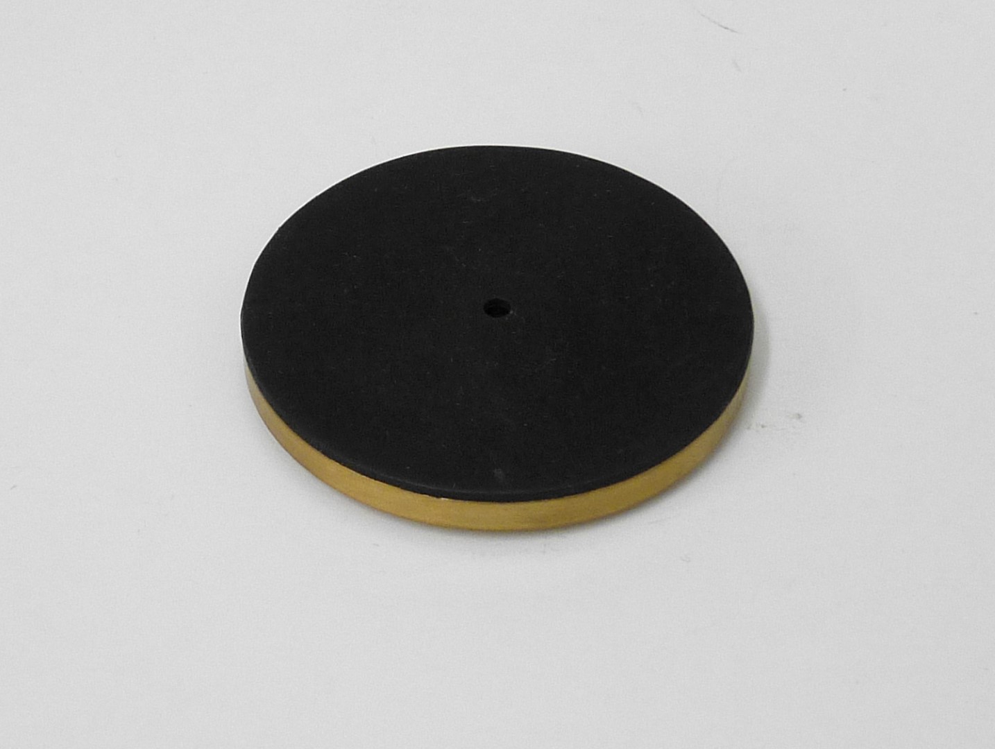
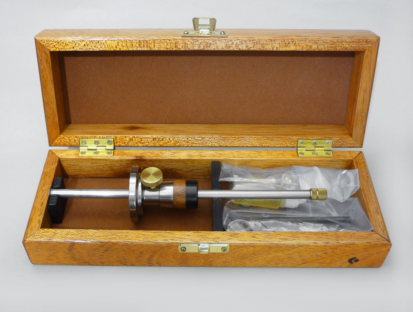
    Additionally, I made a brass pad (55mm in diameter); this is very handy on marking big circles and arcs. On its center there is a press fit piece of Acetal and since Acetal is a low friction material it will enhance the rotation of the gauge. Also, the base of the pad is lined with rubber for better adhesion on slippery surfaces.

    Click image for larger version. 

Name:	P1160707.JPG 
Views:	236 
Size:	207.4 KB 
ID:	40408 Click image for larger version. 

Name:	P1160708.JPG 
Views:	228 
Size:	194.9 KB 
ID:	40409

    Now, I have adjusted the length of the carbide pointing tip so when I will insert it all the way down into the hole and then use it with the brass pad to mark a circle its tip will not leave a mark on the center of the surface.

    Click image for larger version. 

Name:	P1160709.JPG 
Views:	211 
Size:	255.1 KB 
ID:	40410 Click image for larger version. 

Name:	P1160710.JPG 
Views:	257 
Size:	258.6 KB 
ID:	40411 Click image for larger version. 

Name:	P1160711.JPG 
Views:	244 
Size:	228.8 KB 
ID:	40412

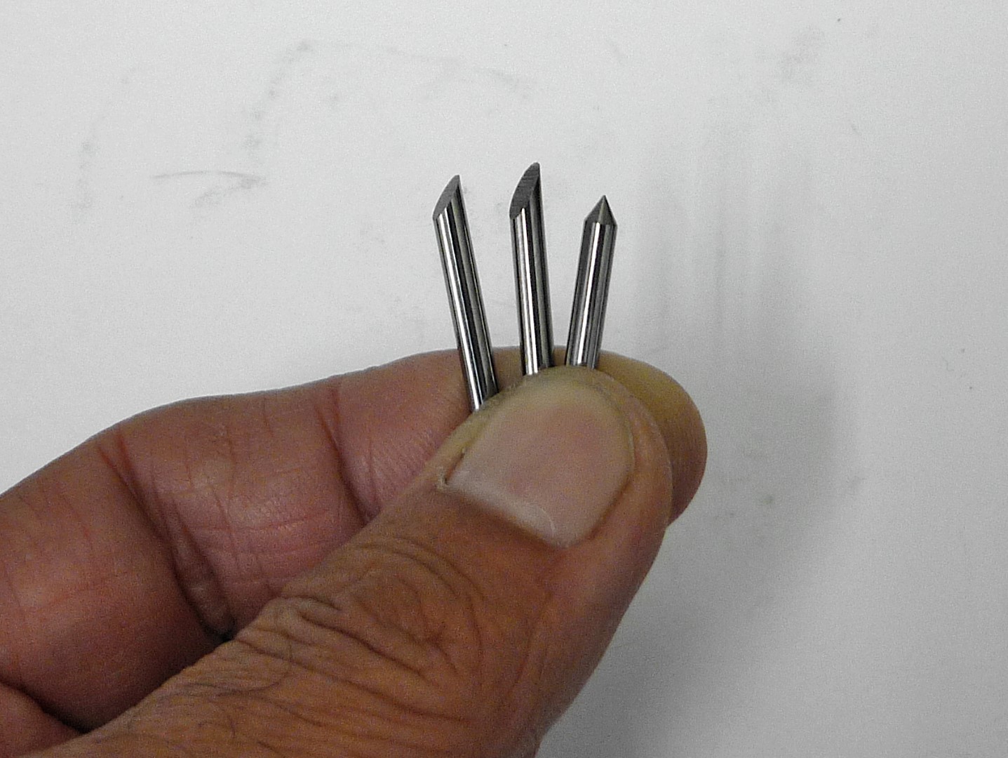
    As for the carbide rods, I have ground two for marking, one at 30 degrees, the other at 45 and the pointing tip at 60 degrees.

    Click image for larger version. 

Name:	P1160712.JPG 
Views:	232 
Size:	299.2 KB 
ID:	40413

    I made a wrench for tightening the cup as well an extra sleeve.

    Click image for larger version. 

Name:	P1160713.JPG 
Views:	224 
Size:	217.6 KB 
ID:	40414 Click image for larger version. 

Name:	P1160714.JPG 
Views:	214 
Size:	213.0 KB 
ID:	40415

    The marking range of the gauge is:

    Using the wheel cutter, from 1.0 up to 180mm

    With the carbide, from 1.0 up to 170mm

    Using the gauge as a compass, I can mark effectively from 25 up to 340mm. If the gauge used in conjunction with the brass pad, then it’s from 55 up 340mm.

    Click image for larger version. 

Name:	P1160719.JPG 
Views:	267 
Size:	252.8 KB 
ID:	40416 Click image for larger version. 

Name:	P1160720.JPG 
Views:	241 
Size:	277.4 KB 
ID:	40417 Click image for larger version. 

Name:	P1160721.JPG 
Views:	235 
Size:	249.1 KB 
ID:	40418 Click image for larger version. 

Name:	P1160722.JPG 
Views:	223 
Size:	322.5 KB 
ID:	40419

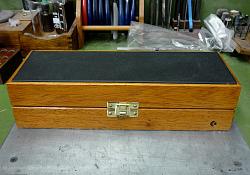
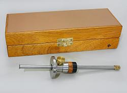
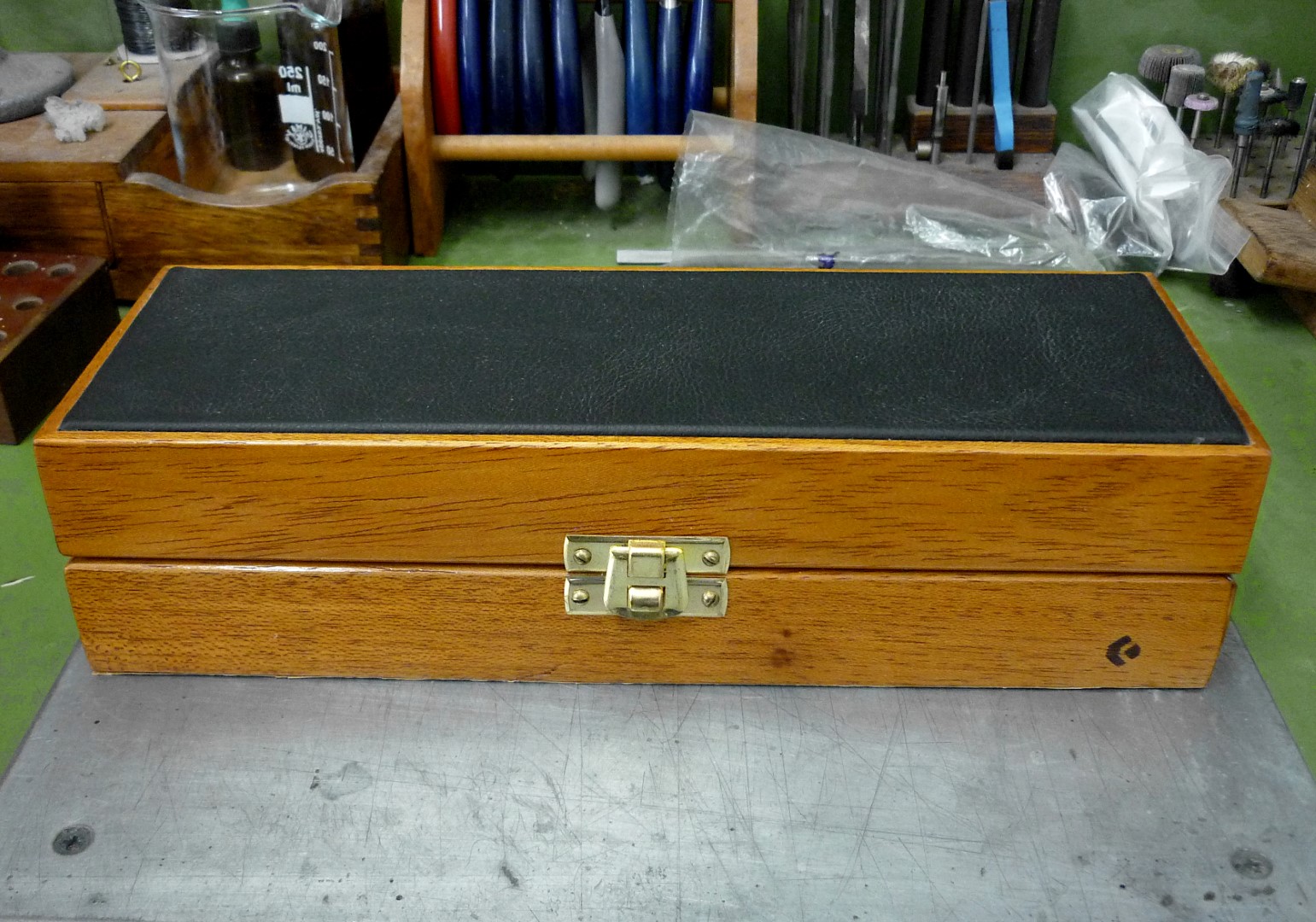
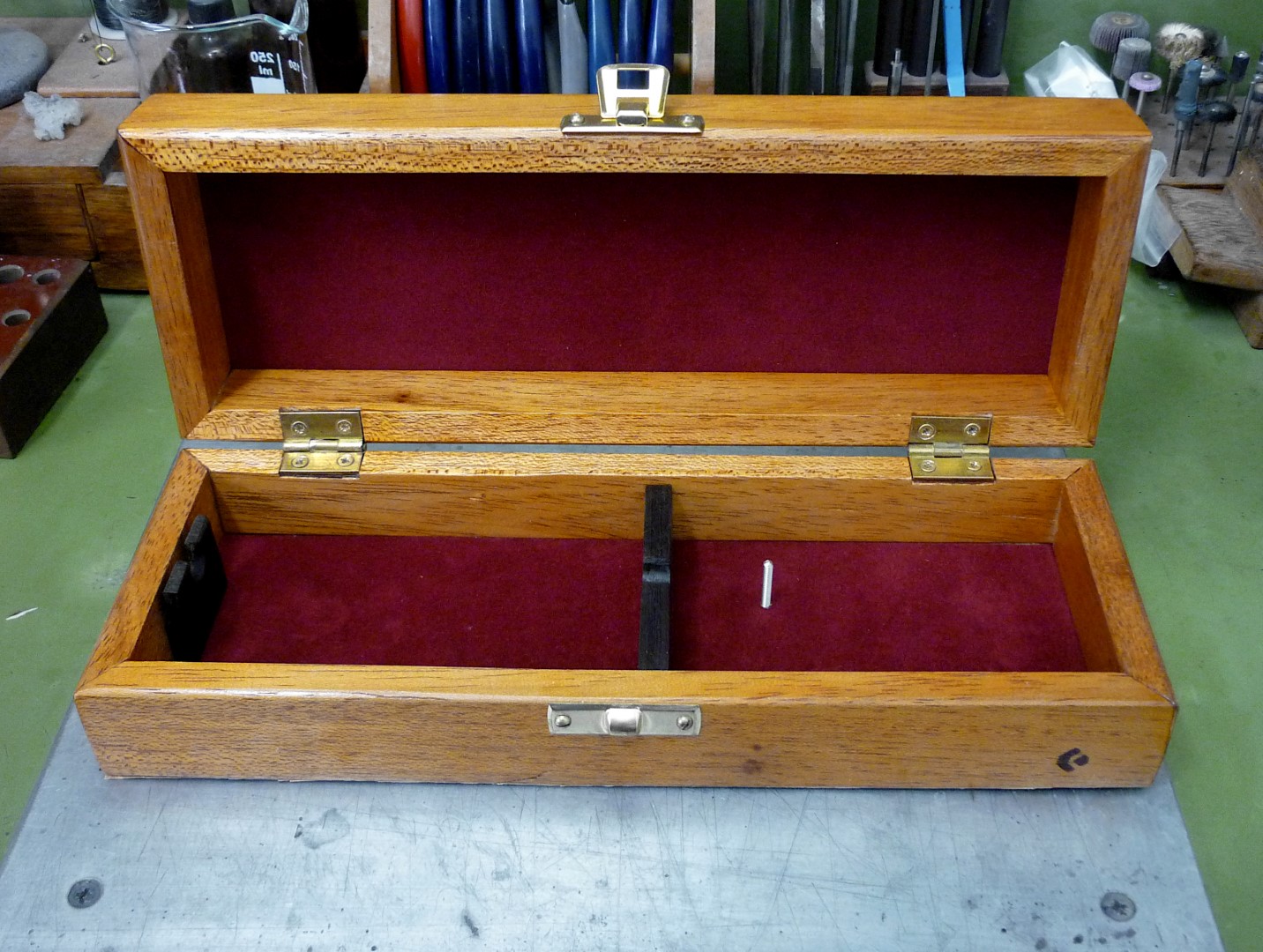
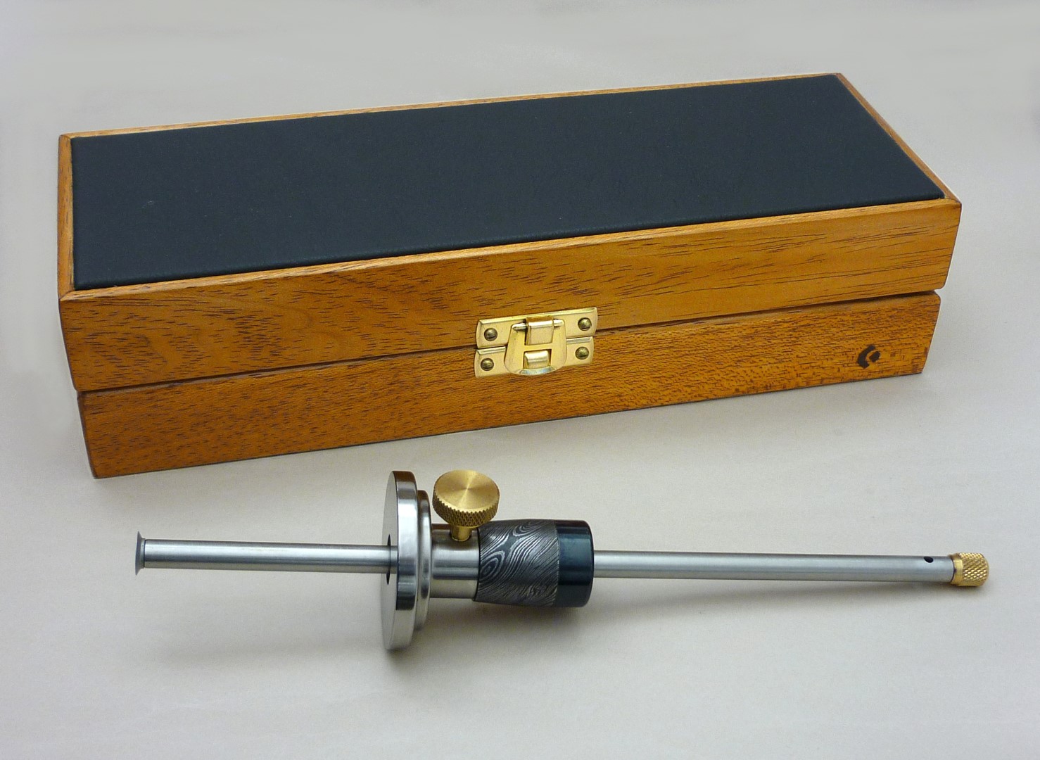
    Finally I made a case from solid Niangon wood, Wenge and plywood. The lid of the case outside is dressed with black leather.

    Click image for larger version. 

Name:	P1160723.JPG 
Views:	247 
Size:	417.3 KB 
ID:	40420 Click image for larger version. 

Name:	P1160724.JPG 
Views:	244 
Size:	387.1 KB 
ID:	40421

    Now, I was so excited with the project and as I'm a bit crazy I made a couple more of these gauges, here are some pictures.

    Click image for larger version. 

Name:	P1160725.JPG 
Views:	224 
Size:	332.1 KB 
ID:	40422 Click image for larger version. 

Name:	P1160726.JPG 
Views:	223 
Size:	106.8 KB 
ID:	40423

    Click image for larger version. 

Name:	P1160727.JPG 
Views:	230 
Size:	292.6 KB 
ID:	40424 Click image for larger version. 

Name:	P1160728.JPG 
Views:	270 
Size:	154.0 KB 
ID:	40425

    Click image for larger version. 

Name:	P1160729.JPG 
Views:	222 
Size:	135.5 KB 
ID:	40426 Click image for larger version. 

Name:	P1160730.JPG 
Views:	244 
Size:	313.0 KB 
ID:	40427 Click image for larger version. 

Name:	P1160731.JPG 
Views:	249 
Size:	334.8 KB 
ID:	40428
    This is a simple one

    Here is a short video to see how it works.


    All the best
    Dimitris

  2. The Following 19 Users Say Thank You to Dimitris Polychronis For This Useful Post:

    anthonyget (Sep 11, 2021), baja (Sep 14, 2021), Dimsa (Sep 13, 2021), Frank S (Sep 14, 2021), Home-PC (Sep 13, 2021), Jon (Sep 11, 2021), lassab999 (Sep 14, 2021), luvmygto (Sep 18, 2021), mackai (Sep 2, 2024), N00b Machinist (Sep 14, 2021), NortonDommi (Sep 15, 2021), nova_robotics (Sep 17, 2021), PJs (Sep 3, 2024), RetiredFAE (Sep 24, 2023), Scotsman Hosie (Sep 13, 2021), sossol (May 3, 2022), Tonyg (Sep 20, 2021), trevor_60_r (Sep 10, 2022), yester145 (Sep 13, 2021)

Thread Information

Users Browsing this Thread

There are currently 1 users browsing this thread. (0 members and 1 guests)

Tags for this Thread

Bookmarks

Posting Permissions

  • You may not post new threads
  • You may not post replies
  • You may not post attachments
  • You may not edit your posts
  •