
 LinkBack URL
 About LinkBacks


This is a specialised tool which will be principally of interest to engine builders, motorcycle and car. Although I can see that the basic idea could be applied in other fields as well.
The problem.
The sealing face of engine valves is not flat but is usually angled at 45 deg. (although in some cases between 30 and 55deg) and that can lead to difficulties measuring the length from face to the end of the stem, and similarly to the retaining collet groove. At times it becomes important to match these dimensions on multiple valves. This morning I decided that I needed to make a holding gadget to make valve matching easy. This post shows the result.
Don't forget to click on the images for full size view.
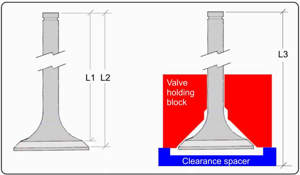
This sketch shows the problem and a possible solution. On the left we have two extremes of length between L1 and L2 and these can vary depending on the diameter and width of the sealing surface. in other words we have no reference surface or line for an accurate measurement. However, if we mount the valve in a block as shown on the right, which is machined at the valve seat angle and has a good fitting hole for the stem, we can see that L3 will be a stable dimension.
The solution in practice.
In addition to getting a useful length reference, another requirement is to be able to mount valves in a lathe or grinder to face off the ends to the same length and also to machine collet retaining grooves in a consistent location. In fact it is the ability to hold a valve for machining that motivated the tool. You can use a valve seat in a cylinder head together with a dial gauge and suitable bracket if measuring was all that you need to do.
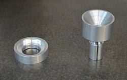
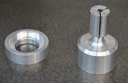
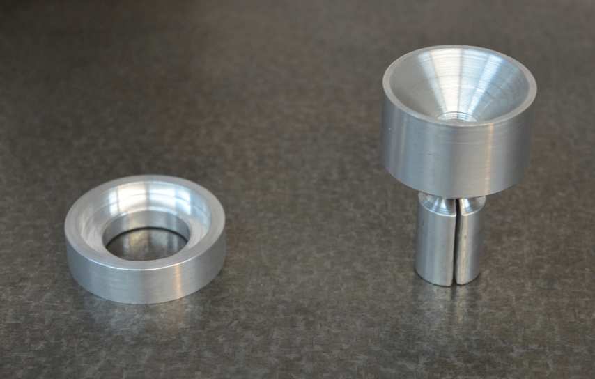
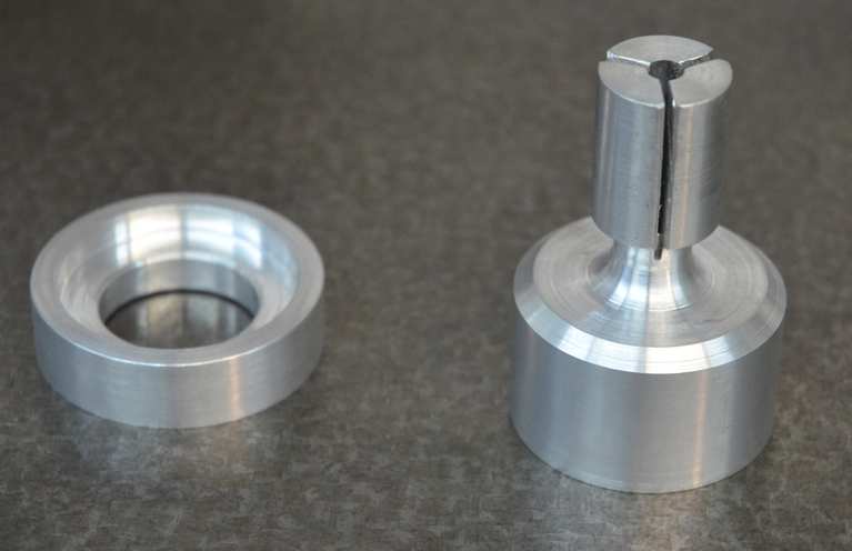
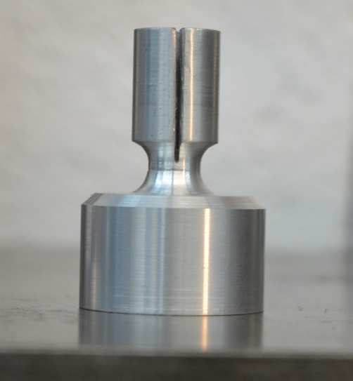
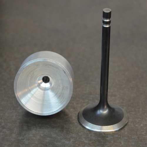
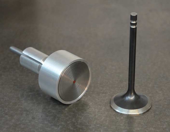
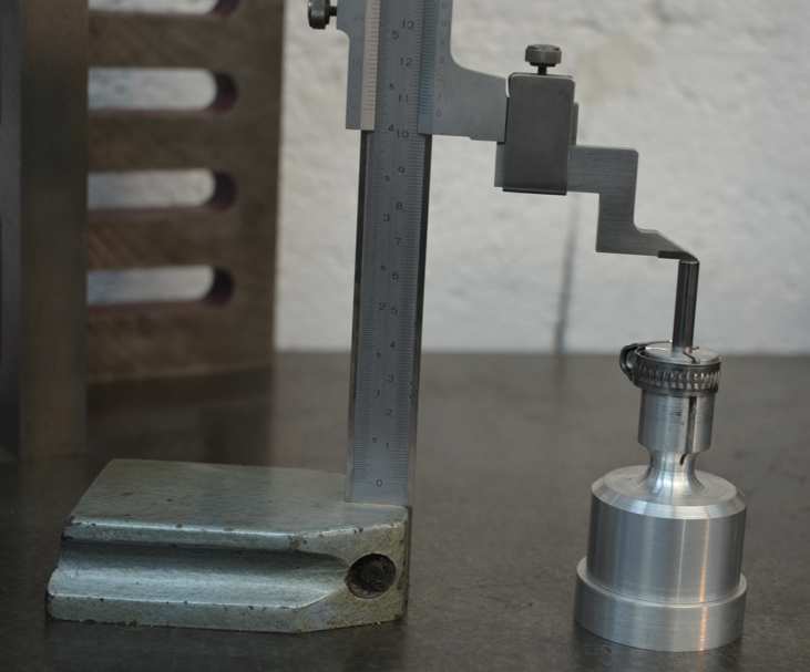
Here is the physical implementation. The ring on the left is simply a spacer to ensure that a valve head which protrudes from the bottom of the block has clearance and doesn't mess up the length measurement. The other piece is the valve holding block. The large end has the 45 deg. taper which allows a large range of valve head sizes to be accommodated. The smaller end is slotted to form a collet to grip the valve stem. The last photo shows a relieving groove to allow the flexibility needed for the collet to work properly.
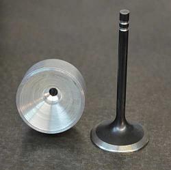
On the left we can see the block and a valve, on the right a valve is loaded.

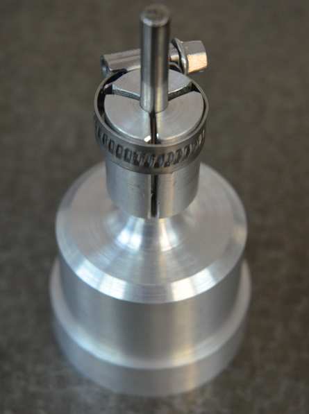
A jubilee clip is an easy way to clamp the collet on to the valve stem. Note the spacer under the valve holder to ensure clearance of the valve head off the surface plate. A vernier height gauge is used to get a stable reference dimension. This tool makes it very quick and easy to check a number of valves for consistency.
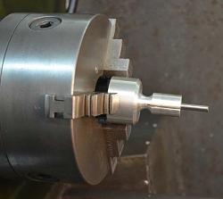

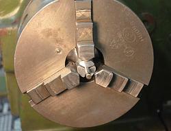
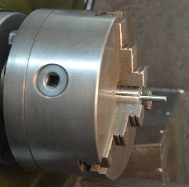
Fitting the valve holder in a 3 jaw chuck. The large end is placed inside the chuck beyond the back of the jaws and closed down. Just prior to clamping on the collet the assembly is pulled forward such that the large end is located by the back of the jaws. This gives a repeatable axial location.
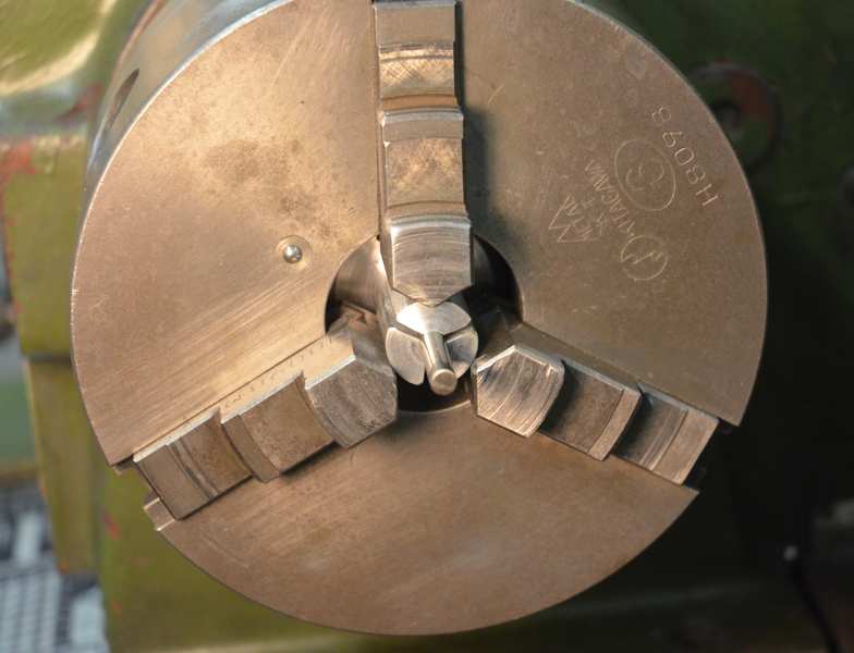
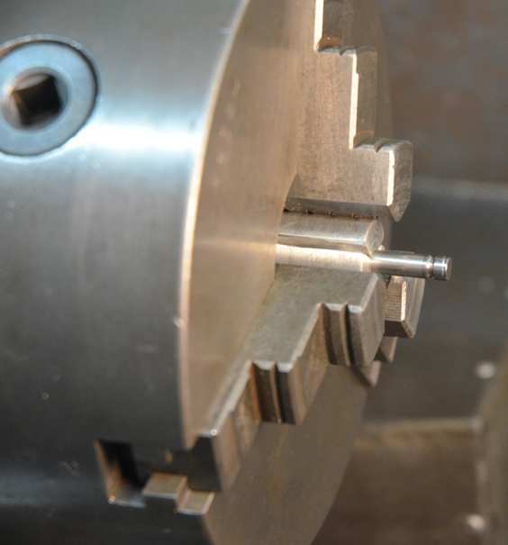
On the left is a clear view of the collet clamping, on the right we can see the valve retaining collet groove as machined with this holding fixture.
Thanks for viewing.


 Reply With Quote

Bookmarks