Free 186 More Best Homemade Tools eBook:  
New: 300+ fresh build posts/day from 275 forums → BuildThreads.com

User Tag List

Page 1 of 3 1 2 3 LastLast
Results 1 to 10 of 28

Thread: Variable Frequency Drive for a larger factory fan

Hybrid View

  1. #1
    Supporting Member chy_farm's Avatar
    Join Date
    Apr 2018
    Location
    Yokohama, Japan
    Posts
    125
    Thanks
    65
    Thanked 221 Times in 63 Posts

    chy_farm's Tools

    Variable Frequency Drive for a larger factory fan

    Last year we had a very hot Summer and Autumn so had a presumption that we should need a very big fan in our shed to get our job easier this year.
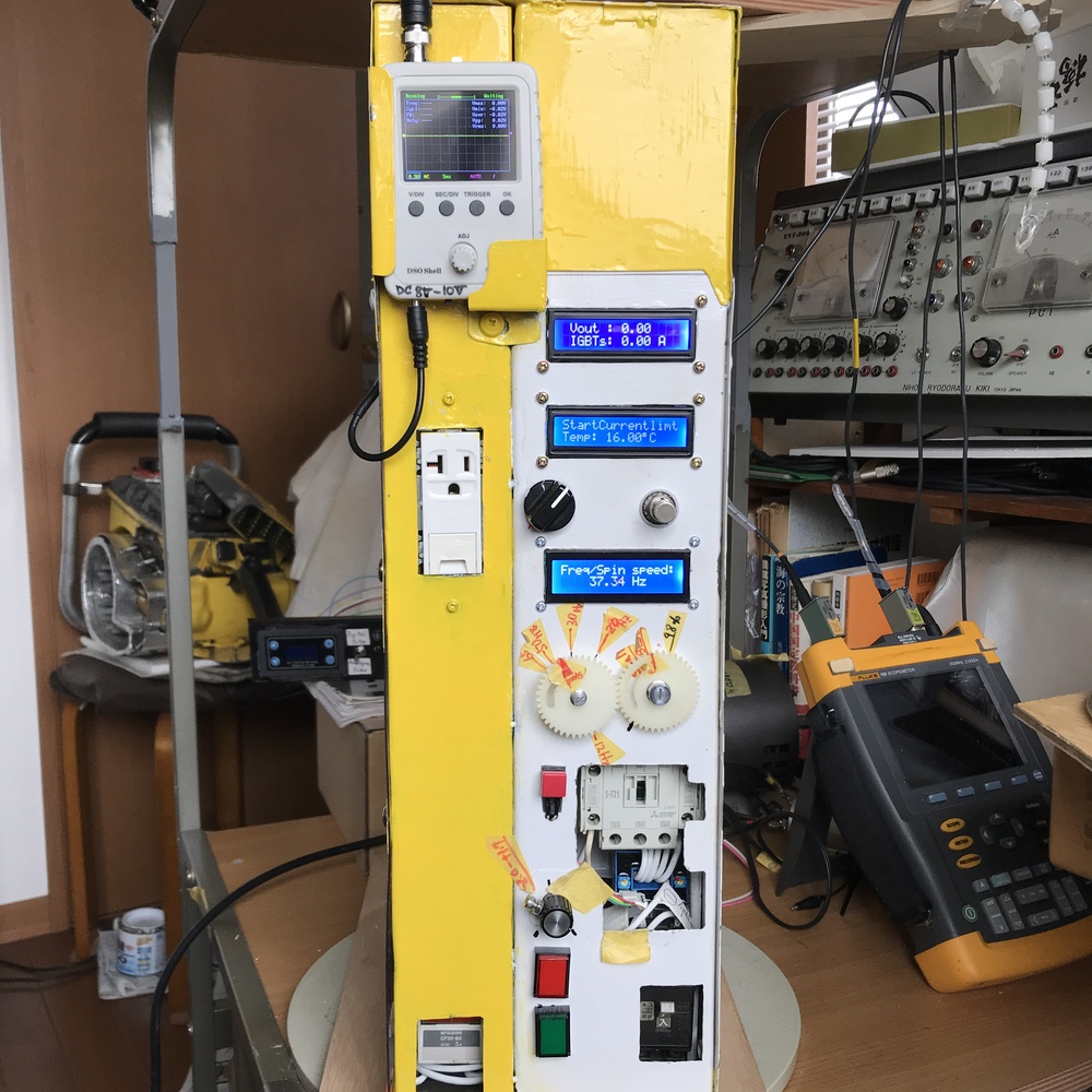
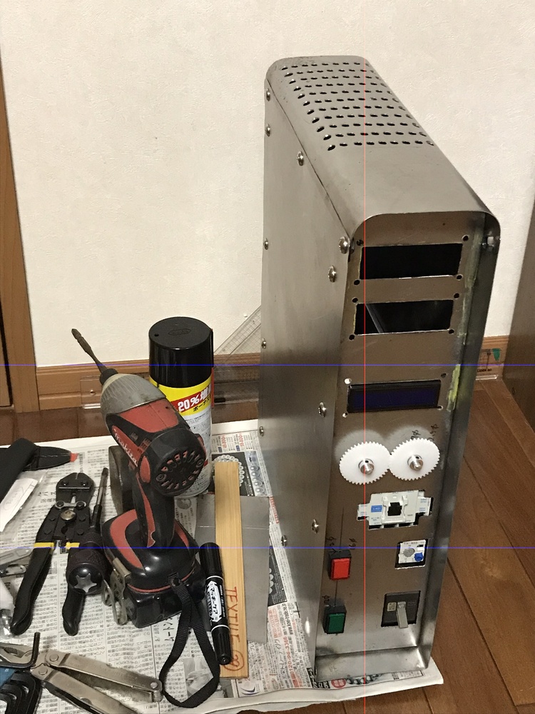
    This motivation gave me a way to build a single phase Variable Frequency Drive for a bigger fan motor!

    Fortunately or unfortunately we have cool Summer now, so not yet get a new big fan yet, nor have a chance to run this VFD...

    Variable Frequency Drive for a larger factory fan-img_4006.jpg

    Variable Frequency Drive for a larger factory fan-img_3995.jpg
    Last edited by chy_farm; Jul 30, 2020 at 07:23 AM.

  2. The Following 2 Users Say Thank You to chy_farm For This Useful Post:

    Jon (Jul 31, 2020), nova_robotics (Jul 30, 2020)

  3. #2
    Supporting Member chy_farm's Avatar
    Join Date
    Apr 2018
    Location
    Yokohama, Japan
    Posts
    125
    Thanks
    65
    Thanked 221 Times in 63 Posts

    chy_farm's Tools
    Variable Frequency Drive for a larger factory fan-illuestration.jpg

    Inside: Triangle and rectangle generators are analogue unit.

  4. The Following User Says Thank You to chy_farm For This Useful Post:

    nova_robotics (Jul 30, 2020)

  5. #3
    Supporting Member chy_farm's Avatar
    Join Date
    Apr 2018
    Location
    Yokohama, Japan
    Posts
    125
    Thanks
    65
    Thanked 221 Times in 63 Posts

    chy_farm's Tools
    Started from these;

    Variable Frequency Drive for a larger factory fan-img_0058.jpg

    Variable Frequency Drive for a larger factory fan-img_0059.jpg


    Making shifts to the frequency is to be done with a couple of white dials, an obsolete analogue way.
    Variable Frequency Drive for a larger factory fan-img_0113.jpg

    Variable Frequency Drive for a larger factory fan-img_0114.jpg

    Chy

  6. The Following User Says Thank You to chy_farm For This Useful Post:

    nova_robotics (Jul 30, 2020)

  7. #4
    Supporting Member chy_farm's Avatar
    Join Date
    Apr 2018
    Location
    Yokohama, Japan
    Posts
    125
    Thanks
    65
    Thanked 221 Times in 63 Posts

    chy_farm's Tools
    But on the way of assembling I found this handmade case was a tad small
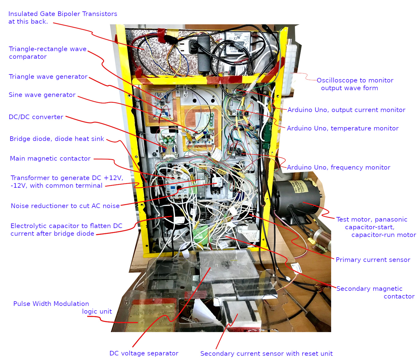
, so added some more rooms ;
    Variable Frequency Drive for a larger factory fan-added_rooms_1.jpg


    Main power board with magnetic contactor and a transformer;
    Variable Frequency Drive for a larger factory fan-transformer.jpg

    Placed a noise filter right after the main contactor;
    Variable Frequency Drive for a larger factory fan-tdk_emc_filer_6ajpg.jpg

    Temperature sensors are placed onto five different part,
    1: Bridge diode (50A),
    2: Short cut unit,
    3: Isolated Gate Bipolar Transistor unit,
    4: High speed diodes for return current re-circulation unit,
    5: Double 2mH filter coils right before the output terminal;
    Variable Frequency Drive for a larger factory fan-tem_sensor_1.jpg

    Output frequency monitor;
    Variable Frequency Drive for a larger factory fan-frequency.jpg

    Output current monitor, and its detector (HAS-50);
    Variable Frequency Drive for a larger factory fan-current_sensor.jpg

    Variable Frequency Drive for a larger factory fan-has_50-s_current_transducerjpg.jpg

    Chy
    Last edited by chy_farm; Jul 30, 2020 at 05:35 PM.

  8. The Following User Says Thank You to chy_farm For This Useful Post:

    nova_robotics (Jul 30, 2020)

  9. #5
    Supporting Member chy_farm's Avatar
    Join Date
    Apr 2018
    Location
    Yokohama, Japan
    Posts
    125
    Thanks
    65
    Thanked 221 Times in 63 Posts

    chy_farm's Tools
    Schematic for power units is;
    Variable Frequency Drive for a larger factory fan-rsz_power_unit_01-02.jpg

    Chy

    please note there may be a wrong design in above drawing.

  10. The Following 2 Users Say Thank You to chy_farm For This Useful Post:

    Carnel (Jul 31, 2020), nova_robotics (Jul 30, 2020)

  11. #6
    Supporting Member chy_farm's Avatar
    Join Date
    Apr 2018
    Location
    Yokohama, Japan
    Posts
    125
    Thanks
    65
    Thanked 221 Times in 63 Posts

    chy_farm's Tools
    A couple of logic units of this type is known as noise-fragile to electro-magnetic noises. This part was one of the complexities to me.
    Variable Frequency Drive for a larger factory fan-noise_shield.jpg

    Units in the right half (marked yellow) are electrically shielded with copper plate around them, they are a triangle wave generator and a wave form comparator, and a sine wave generator.

    These in the left half are also shielded with so called shield wire (black wires), they make up a Pulse Width Modulation logic unit.

    Chy
    Last edited by chy_farm; Jul 30, 2020 at 07:29 PM.

  12. The Following User Says Thank You to chy_farm For This Useful Post:

    nova_robotics (Jul 30, 2020)

  13. #7
    Supporting Member
    Join Date
    Sep 2018
    Posts
    2,923
    Thanks
    13,831
    Thanked 1,782 Times in 1,004 Posts

    nova_robotics's Tools
    That's great. Well done.

    Why three Arduinos?

  14. The Following User Says Thank You to nova_robotics For This Useful Post:

    chy_farm (Jul 30, 2020)

  15. #8
    Supporting Member chy_farm's Avatar
    Join Date
    Apr 2018
    Location
    Yokohama, Japan
    Posts
    125
    Thanks
    65
    Thanked 221 Times in 63 Posts

    chy_farm's Tools
    Good morning Nova, Why? ,,, only because I did not know other ways, lol. Do you make them in one Uno?
    Chy

    p.s. Glad to know you are a specialist of robotics, Nova!
    Last edited by chy_farm; Jul 30, 2020 at 07:37 PM.

  16. #9
    Supporting Member
    Join Date
    Sep 2018
    Posts
    2,923
    Thanks
    13,831
    Thanked 1,782 Times in 1,004 Posts

    nova_robotics's Tools
    Quote Originally Posted by chy_farm View Post
    Good morning Nova, Why? ,,, only because I did not know other ways, lol. Do you make them in one Uno?
    Chy

    p.s. Glad to know you are a specialist of robotics, Nova!
    Shoot me your code. I can have a look at it if you want. Are you bit-banging the Arduino functions? Interrupts and PWM outputs are very, very nice when you get them set up. If you swapped the three Arduino Unos out for one Arduino Due you can definitely monitor current, frequency and temperature with a single board, but you could probably also generate your sine waves. Arduino Dues are very fast. There are also lots of other (and much faster) boards to choose from as well. If you're having frequency and noise issues driving it directly from a microcontroller might solve some oscillator problems.

    Again, awesome project and great work.

  17. #10
    Supporting Member chy_farm's Avatar
    Join Date
    Apr 2018
    Location
    Yokohama, Japan
    Posts
    125
    Thanks
    65
    Thanked 221 Times in 63 Posts

    chy_farm's Tools
    Quote Originally Posted by nova_robotics View Post
    Shoot me your code. I can have a look at it if you want. Are you bit-banging the Arduino functions? Interrupts and PWM outputs are very, very nice when you get them set up. If you swapped the three Arduino Unos out for one Arduino Due you can definitely monitor current, frequency and temperature with a single board, but you could probably also generate your sine waves. Arduino Dues are very fast. There are also lots of other (and much faster) boards to choose from as well. If you're having frequency and noise issues driving it directly from a microcontroller might solve some oscillator problems.

    Again, awesome project and great work.
    Nova, thank you very much for your kindness.
    This information is very big for me, for years I have been learning C, but not yet graduate from a first grade though, lol.
    When I got to know Arduino, was a bit disappointed that it uses C++, which uses 'Class', this makes me mixed up and still I am loosing my way to restart learning.

    So this offer is very great to me! Perhaps you make me stand again and start again Nova. Will try posting the code and ask you for your information.
    Many thanks!!

    Chy

Thread Information

Users Browsing this Thread

There are currently 1 users browsing this thread. (0 members and 1 guests)

Bookmarks

Posting Permissions

  • You may not post new threads
  • You may not post replies
  • You may not post attachments
  • You may not edit your posts
  •