
 LinkBack URL
 About LinkBacks


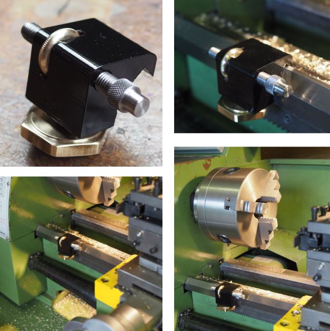
Although I'm not a big fan of lathe saddle stops I've got to the point where I thought it might be a good idea for certain repeat tasks and hence I've set out and made this for the Warco WM240B lathe.
The result is a cast iron block that hangs over the saddle and locks with a nut. The stop itself then is a threaded bar that has a simple locking knurled wheel. All quite simple to make and more details are here: Warco Saddle Stop


 Reply With Quote

Bookmarks