Free 186 More Best Homemade Tools eBook:  
Get 2,000+ tool plans, full site access, and more.

User Tag List

Page 1 of 2 1 2 LastLast
Results 1 to 10 of 16

Thread: 2 cycle combustion chamber repair

  1. #1
    Supporting Member hemmjo's Avatar
    Join Date
    Feb 2017
    Posts
    2,542
    Thanks
    224
    Thanked 1,446 Times in 820 Posts

    hemmjo's Tools

    2 cycle combustion chamber repair

    This is more a process than a tool and is still being developed. I am seeking some input from others. I have tried to provide enough information to put the process into perspective.

    I need some suggestions on restoring a 2 cycle combustion chamber.

    Background-
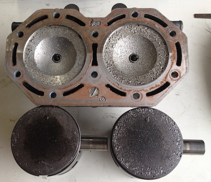
    I am rebuilding a Personal Water Craft engine. I purchased this rebuilt engine from a big name PWC engine rebuilder. I will never purchase anything from them again. The engine failed, due to incorrect parts being used to assemble it, damaging the pistons, cylinder head and cylinder walls. The damage was created by small locating pins that worked their way out of the crank bearings because the incorrect (too large) thrust ring prevented the case halves from pulling tightly together.
    — damaged head/pistons photo
    2 cycle combustion chamber repair-1-damaged-headpistons.jpg

    Progress
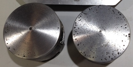
    I was able to hone the cylinders so they are still within the specifications. I have worked on the pistons, they will clean up. I will need to balance them when I get finished with that. I will be able to account for the “shorter” pistons with a thinner base gasket for the cylinder or cutting the head.
    — pistons photo
    2 cycle combustion chamber repair-2-pistons.jpg

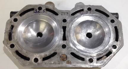
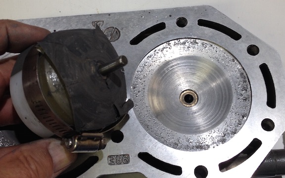
    I am currently working on the head. Since the engine was previously rebuilt and I do not trust the rebuilder, I could not be sure the combustion chambers were the correct profile to begin with. I purchased another cylinder head with one good chamber, the other chamber was damaged by what I suspect was detonation. Possibly due to an air leak in the crankcase. I will also be able to repair this head to use on a spare engine I am also building
    —good chamber photo
    2 cycle combustion chamber repair-3-goodchamber.jpg

    Making a form tool to fit the chamber.
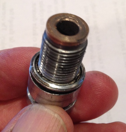
    I polished and waxed the good chamber. Then removed the ceramic electrode from an old spark plug. Turned the ground electrode off the end. Then bored the plug to fit a bronze bushing inside.
    —Spark plug photo
    2 cycle combustion chamber repair-4-sparkplug.jpg

    Then I made a mandrel by cutting the head off a 1/2” bolt. Threaded 2 nuts on the end and jammed them tight against the shank of the bolt. The nuts give the resin something to grip to resist torque. Then turned the end of the bolt to fit the bushing I put in the spark plug. With the plug screwed into the head, I leveled the head so the resin will flow into the chamber level. Then inserted the mandrel into the bushing. Then mixed and poured polyurethane resin into the chamber to create a form tool with the correct shape.
    —form tool photo
    2 cycle combustion chamber repair-5-form-tool.jpg

    The problem-
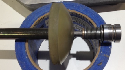
    After the resin cured I was able to attach some sand paper to the form to remove the dings from the chamber. The process worked OK, but not great. I was quickly and easily able to remove the dings from the chamber. However it I am not able to get finer grades of paper to conform well enough to the shape of the tool. The little wrinkles in the paper causes grooves in the chamber. It needs to be smooth to prevent detonation.
    — chamber and tool photo
    2 cycle combustion chamber repair-6-chamber-tool.jpg

    After I find a good way to finish the chamber I can use that technique to clean up the squish band. Then CC the head and cut the surface as required to bring it back into specification according to how the pistons and deck height come out.

    I have tried valve grinding compound on the bare from tool, it might work, but I am not able to find various grit sizes here locally. If anyone has other suggestions for a better way to get the abrasive to fit the form tool….I am listening.

    Thanks,

    John

    186 More Best Homemade Tools eBook

  2. The Following 2 Users Say Thank You to hemmjo For This Useful Post:

    blkadder (Jul 5, 2017), Seedtick (Jul 5, 2017)

  3. #2
    pennswoodsed's Avatar
    Join Date
    Nov 2013
    Posts
    7
    Thanks
    23
    Thanked 2 Times in 2 Posts
    Hi,
    That looks like it was detonating massively ! I found your resin grinding tool interesting . If you search 2 stroke cylinder head repair you will find a wealth of info .Some techniques may require machinery you do not possess,but could work around. Perhaps if you post your location someone nearby might help?
    Regards,Ed

    2000 Tool Plans

  4. #3
    Supporting Member hemmjo's Avatar
    Join Date
    Feb 2017
    Posts
    2,542
    Thanks
    224
    Thanked 1,446 Times in 820 Posts

    hemmjo's Tools
    Thank you for your reply. Actually ALL piston and head damage was caused by the small steel pins that came out of the crank bearings.

    I did extensive searching before posting to this forum. I really did not find a solution for the equipment I have. My small shop as an 11" lathe, drill press and grinder. My lathe is not large enough to mount the head so a chamber is centered. The head measures 10 1/2 inches along the longest dimension, so I am able to surface the head on my lathe.

    Right now I am trying various ways to attach sandpaper to the tool I have made without having ridges where the flat paper crinkles around the curves of the tool.

    Thanks,

    John
    Central Ohio

  5. #4
    Supporting Member olderdan's Avatar
    Join Date
    Jun 2016
    Posts
    781
    Thanks
    1,456
    Thanked 1,531 Times in 463 Posts

    olderdan's Tools
    Hi Hemmjo
    Wow sure made a mess of that engine.
    Unfortunately any form of purely circular lapping will always leave a grooved finish due to trapped debris and media, but you can certainly remove metal to a point. You could try gluing thin strips of emery radially to get over the wrinkling, that may help to give the debris somewhere to go, after that for me it would be down to hand finishing, a mirror finish is not necessary or even desirable, just smooth. Now I know what machinery you have, after finishing the chamber you could machine the squish band using an angle plate on the lathe crosslide and a boring head.
    2 cycle combustion chamber repair-angle-plate.jpg
    I have done more than a few jobs in this fashion using my drill table as a large angle plate.
    The only problem I can see then is balancing the combustion chamber volume, you can do this using a measuring burette and paraffin but it takes a long time.
    You seem determined so I am sure you will end up with a usable engine.

  6. #5
    BigDude's Avatar
    Join Date
    May 2016
    Posts
    3
    Thanks
    3
    Thanked 0 Times in 0 Posts
    Perhaps using some burlap instead of sand paper. Impregnate the burlap with your honing compound?

  7. #6

    Join Date
    Dec 2016
    Posts
    1
    Thanks
    0
    Thanked 0 Times in 0 Posts

    combustion chamber finishing tool

    Quote Originally Posted by olderdan View Post
    Hi Hemmjo
    Wow sure made a mess of that engine.
    Unfortunately any form of purely circular lapping will always leave a grooved finish due to trapped debris and media, but you can certainly remove metal to a point. You could try gluing thin strips of emery radially to get over the wrinkling, that may help to give the debris somewhere to go, after that for me it would be down to hand finishing, a mirror finish is not necessary or even desirable, just smooth. Now I know what machinery you have, after finishing the chamber you could machine the squish band using an angle plate on the lathe crosslide and a boring head.
    Click image for larger version. 

Name:	angle plate.jpg 
Views:	356 
Size:	263.9 KB 
ID:	18743
    I have done more than a few jobs in this fashion using my drill table as a large angle plate.
    The only problem I can see then is balancing the combustion chamber volume, you can do this using a measuring burette and paraffin but it takes a long time.
    You seem determined so I am sure you will end up with a usable engine.
    Just an idea for the resin,combustion chamber sanding tool.Eastwood(and others)sell loose grit for making buffing wheels.I'm not sure,but I think they sell the adhesive too.The idea is to spread the glue on the buffing wheel,then roll it in the grit of your choice and wait for it to dry.You could use the same principal,OR,the reverse.If you could think of a product to coat the combustion chamber that would lightly hold a layer of grit(say,hot wax?)then pour polyurethane in as you did before,grit would embed in the poly and wouldn't need glue?

  8. #7
    Banned
    Join Date
    Jul 2016
    Posts
    23
    Thanks
    18
    Thanked 1 Time in 1 Post
    To improve the use of abrasive sheets I suggest cutting the sheet in the following manor.
    1) Cut a disk with a diameter that covers your form tool plus enough to clamp on.
    2) Cut triangular slits (maybe 5 - 8) out of the disk. The slits should be oriented with the apex near the center of the disk and the base (shortest side) of the triangle on the circumference of the disk. Size the slits to get maximum coverage of the form, without any overlap.

    The finished abrasive disk will look similar to a daisy flower (with petals) and should improve your metal removal.

    Besides the flower petal approach, I suggest using an abrasive sheet with Pressure Sensitive Adhesive (PSA) on the back and eliminate the hose clamp altogether.
    "3M Stikit" (or equivalent) disks w/ silicon carbide abrasive are easily available on-line in a full range of grit grades.

  9. #8
    Supporting Member markfitz's Avatar
    Join Date
    Apr 2016
    Location
    Phoenix, AZ
    Posts
    19
    Thanks
    0
    Thanked 58 Times in 13 Posts

    markfitz's Tools
    Back in my wild youth I was a mechanic and service manager for a Yamaha dealer in California and did some dirt track racing with 2-strokes. You do not need to worry about pits in the combustion chamber. They will not measurably impact performance. But removing a lot a material in an attempt to make it look good will. Removing material will reduce the effective compression ratio, reducing power output. Having unequal volumes in the two combustion chambers will create differing power output from the cylinders, resulting in increased crankshaft bearing wear and increased vibration.

  10. #9
    Supporting Member blkadder's Avatar
    Join Date
    May 2012
    Location
    Florida, USA
    Posts
    168
    Thanks
    520
    Thanked 69 Times in 36 Posts
    Just a suggestion, but you could use your resin dome and some cloth with polishing compound on it. Leave out the center pin and oscillate the drill as you turn it. That should help alleviate the circular grooves in the head. What the others here said makes a lot of sense, as taking too much metal out of the head can change the size of the combustion chamber, but if you use a fine cut polishing compound that should slow down the amount of metal taken off when compared to emery cloth or sandpaper. Just a thought.
    Ron

    ...Semper Fidelis...

  11. #10
    Supporting Member hemmjo's Avatar
    Join Date
    Feb 2017
    Posts
    2,542
    Thanks
    224
    Thanked 1,446 Times in 820 Posts

    hemmjo's Tools
    PERFECT!! Thanks for the input. I used several of your ideas.

    In regard to chamber defects. This is not a racing engine so I do believe that some defects are OK but sharp edges are bad. Sharp edges stay hotter and can cause detonation if conditions are pressed to the limit, for whatever reason, most typically a lean condition or even bad fuel.

    I cut the pilot off the end of my tool. Then faced the end of the shaft so it was a little up inside of the resin dome. Stretched a piece of shop rag over the dome and secured it to the shaft with a hose clamp. Used my lathe instead of the drill press so I can slow the speed way down. Covered the ways on my lathe with a shield I keep on hand. Dipped the tool in water to soak the rag. Smeared some valve grinding compound the rag. The "osilated" the head around as the dome worked in the chamber. It took only about 15 minutes for each one. They look great.

    The reason that I purchased that additional head with the good chamber was so I would know how many CC's and that shape the chamber should be. As I have learned from other sources this company that rebuilds most of the PWC engines in the USA, cuts the chambers to reduce compression, so their engines will be less likely to fail during their warranty period. Both of the chambers on the damaged head from my engine were 37.25cc before i started. I have not checked them since I cleaned them up, but I will before I work on the squish band. I will make them the same before I work on the squish band, and then again after that. The undamaged chamber on the head I purchased for reference was 36.5cc.

    Again, thanks for the input, I will send a photo when the head is finished.

    John

Thread Information

Users Browsing this Thread

There are currently 1 users browsing this thread. (0 members and 1 guests)

Bookmarks

Posting Permissions

  • You may not post new threads
  • You may not post replies
  • You may not post attachments
  • You may not edit your posts
  •