
 LinkBack URL
 About LinkBacks


Hi again,
The ball and radius turning attachment is the very first tool Ive made for my lathe; in reality the design¹ and the making of this tool is shared 50-50 with an old friend from a machining forum here in Greece.

In one of the first web searches I found Steve Bedair's ball turning toolpost: Steve Bedair / Ball Turning Toolpost
nice design but not exactly what I wanted for my lathe.
I continued my search and that time was when I found for the first time toolsandmods. One of the projects there was a ball turning tool: http://www.toolsandmods.com/docs/ral...rning_tool.pdf the tool is designed to fit on 7 x 12 mini lathes, similar to the Sieg C3.
Looking at the drawings I found that the cross slide of a 7 x 12 mini lathe had the same design with my lathe but with smaller dimensions; it was what I needed, the only difference was that it couldn't turn radius on parts and that was what I added in the original design¹. From that it was easy to make the necessary changes on the measurements.
Now as I have mention in another post I dont know how to make drawings, so my forum friend (who had a milling machine) helped me by making the drawing for the tool based on my measurements and the idea for the radius turning feature. He drew up the tool on Sketchup so that we have it as basic reference.
I did the needed lathe work, filing and finishing, he did all the milling operations. After we finished with the tool we agreed to post it on Sketchups 3D warehouse so to be free for download from anyone that would been interested.
Here is the link: https://3dwarehouse.sketchup.com/mod...ing-attachment note that you can see or change the dimensions after you download it. The dimensions of the tool are for the Optimum D180x300 lathe or similar in center height lathes².
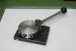
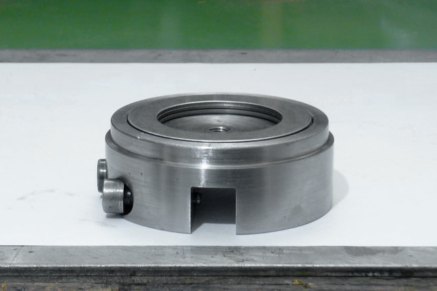
I have to mention that the size of this tool is overkilled, meaning that it doesn't need to have so wide base plate, a round body of this size as well as a lengthy arm like my tool has; let me explain a bit more.
The tool it can make a sphere up to 59 mm in diameter (its not wise though, to exceed the safe limit of the 50mm). So having a main body of 64.50mm in diameter and an arm with 70mm in length, the only that can give is trouble; because you will need to keep bigger distance from the chuck when you will need to make small spheres since the base of the arm will protrudes much more from the main body and could possibly hit on the chuck. Plus that you will have an overhanging part, with more flex and vibrations (depending on the diameter of the material in use) as it will want to climb on the cutting tip especially on potential deeper cuts.
To sum up, if you have a lathe similar with mine and you interested to make this tool, I suggest you to make the main body somewhere around 55mm in diameter, a base plate with an appropriate size so to accommodate the diameter of the body and as for the arm must not exceed 60mm in length.
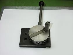
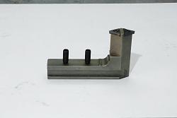
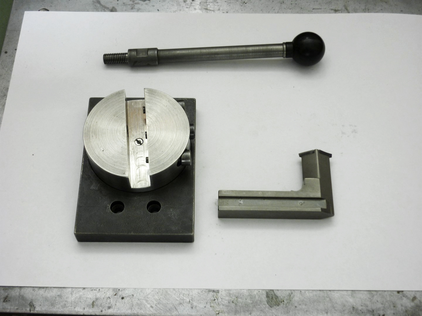
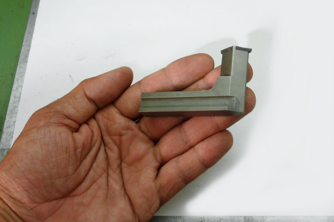
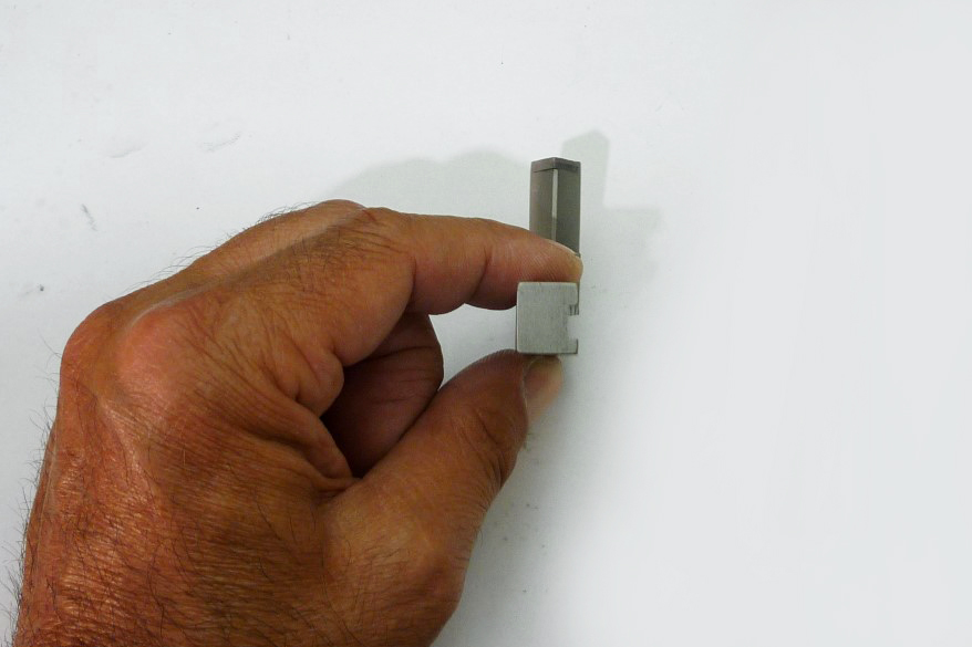
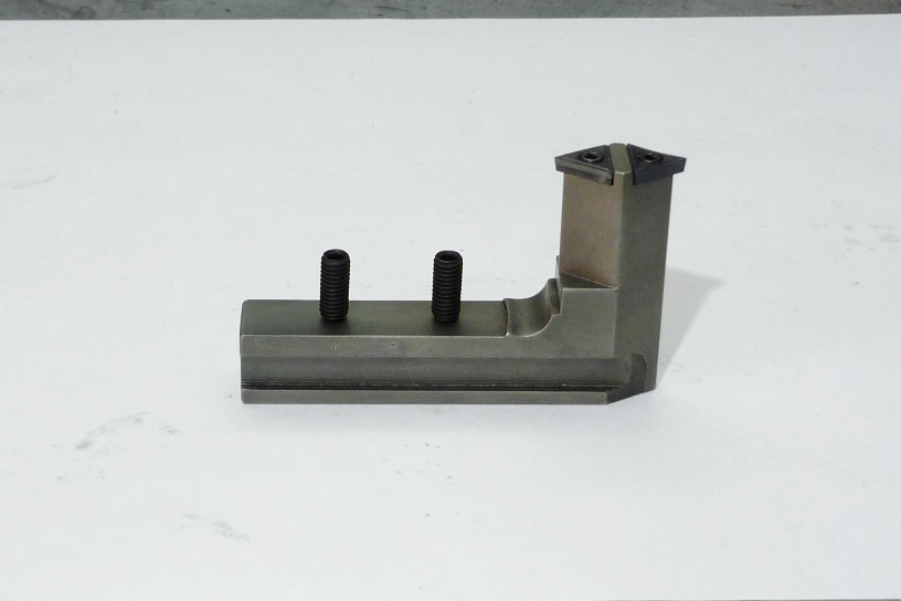
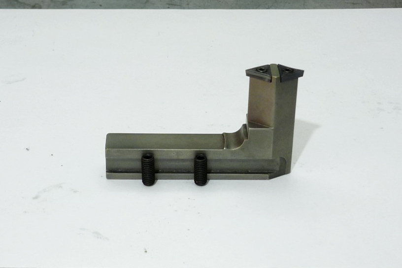
Now, one of our mistakes was that we didnt think to draw and make a second slot³ on the base of the arm so to make it more secure when I wanted to reverse it for turning radiuses.

As I said before the dimensions of the tool are for my lathe - Optimum D180x300 having a center height² of 90mm; I have heard though for slight differences on the center height (+/- 1mm) in the exact model of my lathe from other hobbyist.
So, in order for you to set the cutting tip precisely at the center height of your lathe I suggest you to do this: drill and tap two holes on the base of the arm for a 5 or 6mm set screws (it is important that the height of the set screws to not exceed the height of the arms base).
Something that its also important, is that if you use set screws for height adjustment and you planning as well to make the side slots³ on the arms base, you must not forget to leave enough clearance for the up and down movement so the locking screws on the main body will not interfere while adjusting the height.
Another advantage of using set screws for the height adjustment, is that you can set the cutting tip so as to have a positive, normal or negative rake (depending on the material you will turn, the size of the sphere or the arc you going to make and the depth of cut).
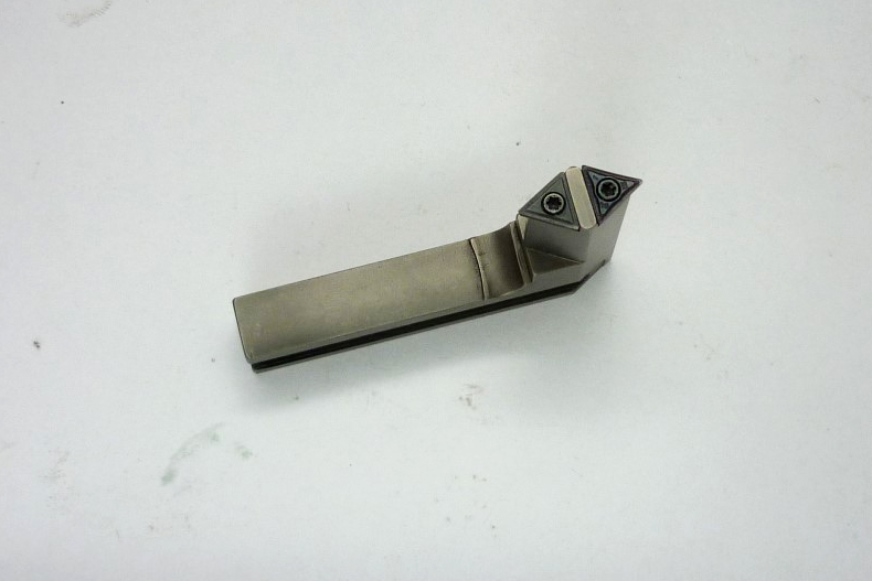
I use TCMT 110204 carbide inserts for my tool, but its up to you what insert you want to use since that you can change the dimensions after you download the drawing.
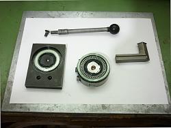
The arm is the only, heat treated part (case hardened)
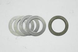
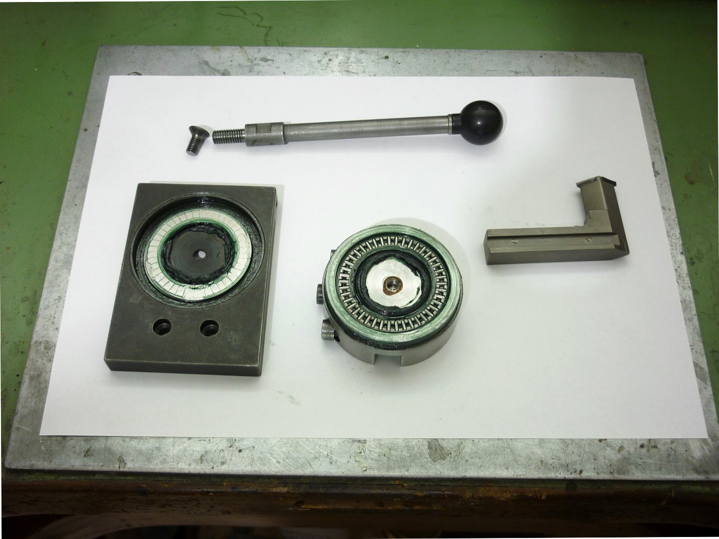
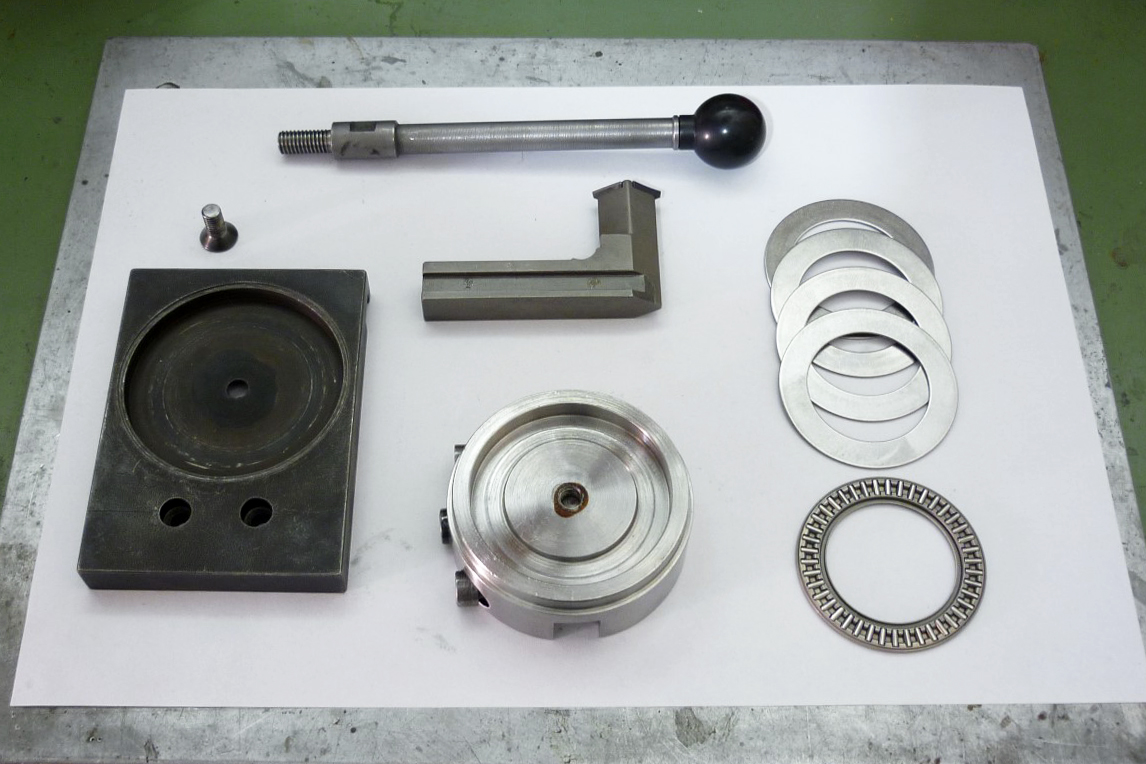
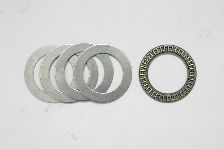
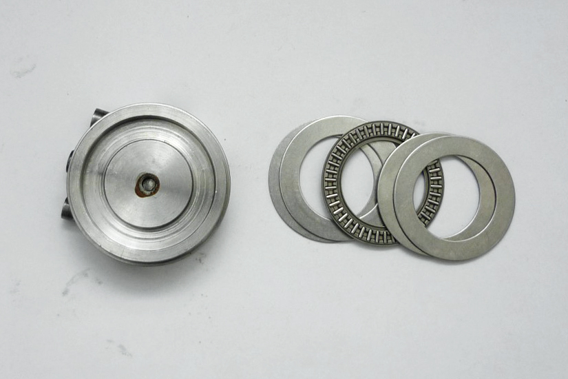
The bore at the bottom of the main body was initially designed for using a 51107 thrust bearing but without the supplied washers, but I changed it because I realized that the hardened balls could wear out the base and the body with use. So, I used an SKF needle roller thrust bearing with 2 washers for each side (total thickness 6.0mm) so to reach the right height as the main body will set in the base plate as well as to have some clearance for preloading, that means that I had to decrease the depth of the bore by taking a cut at the face of the shoulder, so the depth of the bore became 5.93mm (I hope that this makes sense).
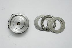
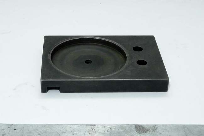
One last feature weve added to the design of this tool is the tiny shoulder on the base plate for keeping the movement of the body free and the bearing clean from metal chips or any other debris from turning.
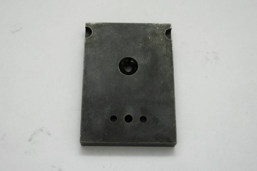
The two hemispherical pockets you see on the upper corners on the bottom of the base plate, is for setting the base without to interfere with the oilers of the cross slide, something that you will not need to do if you make the base smaller in size.
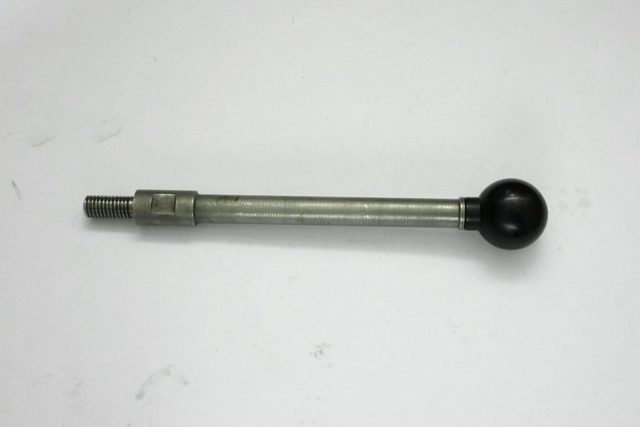
As for the plastic ball on the handle...that was the first thing I've made with this tool.
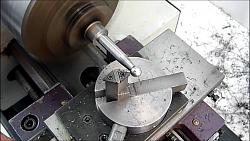
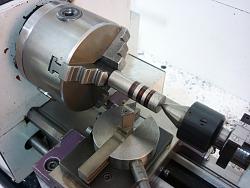
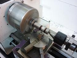
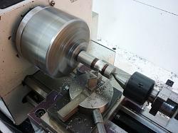
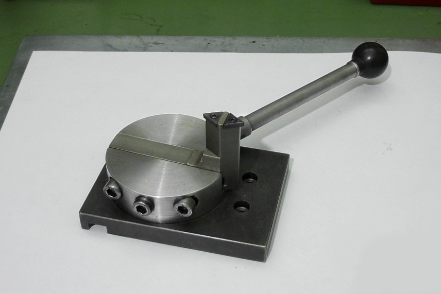
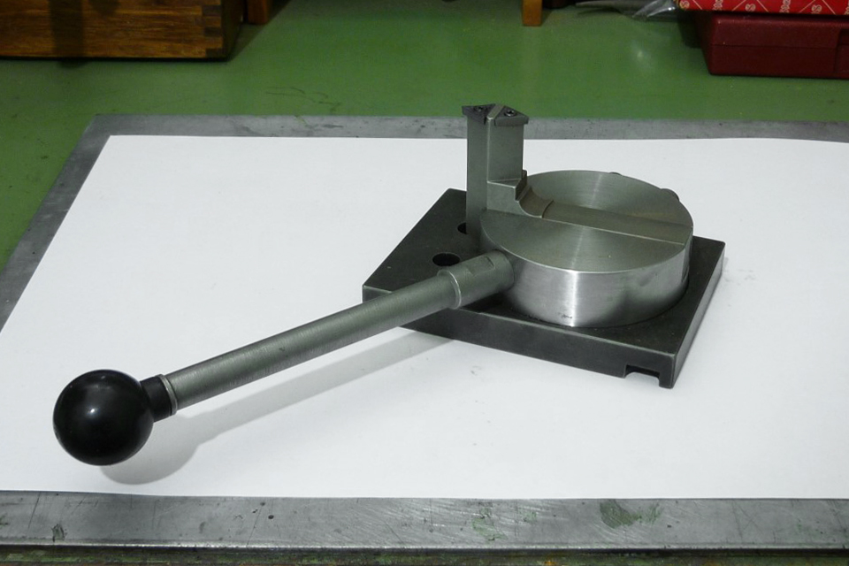
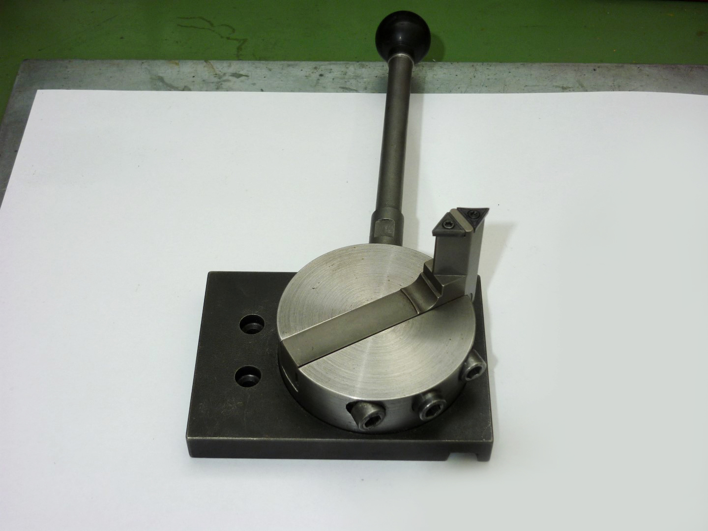
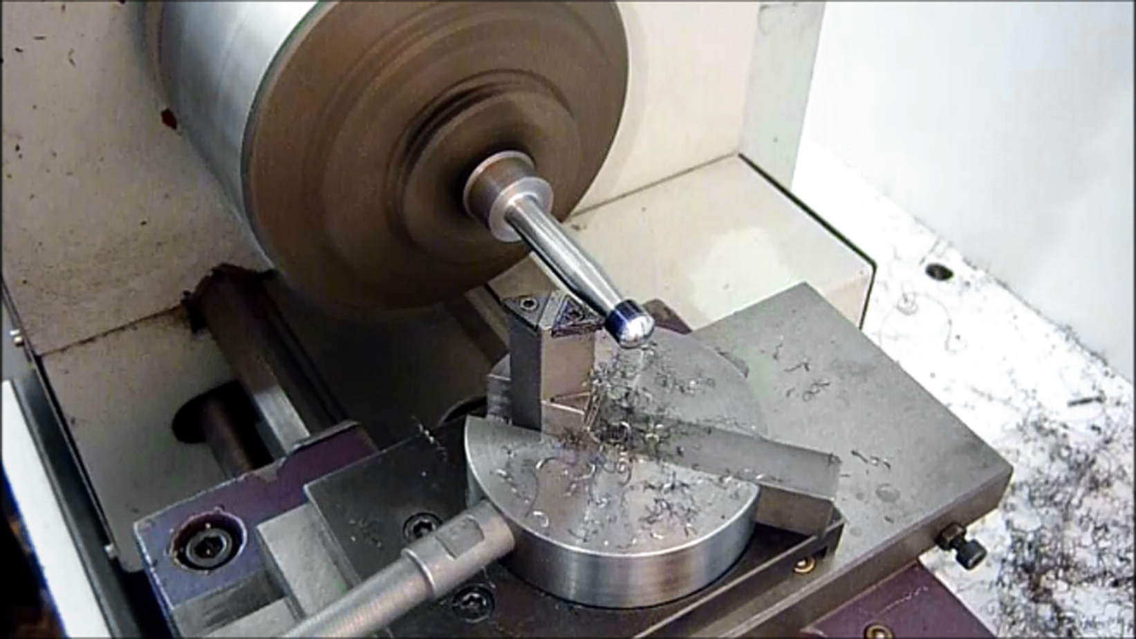
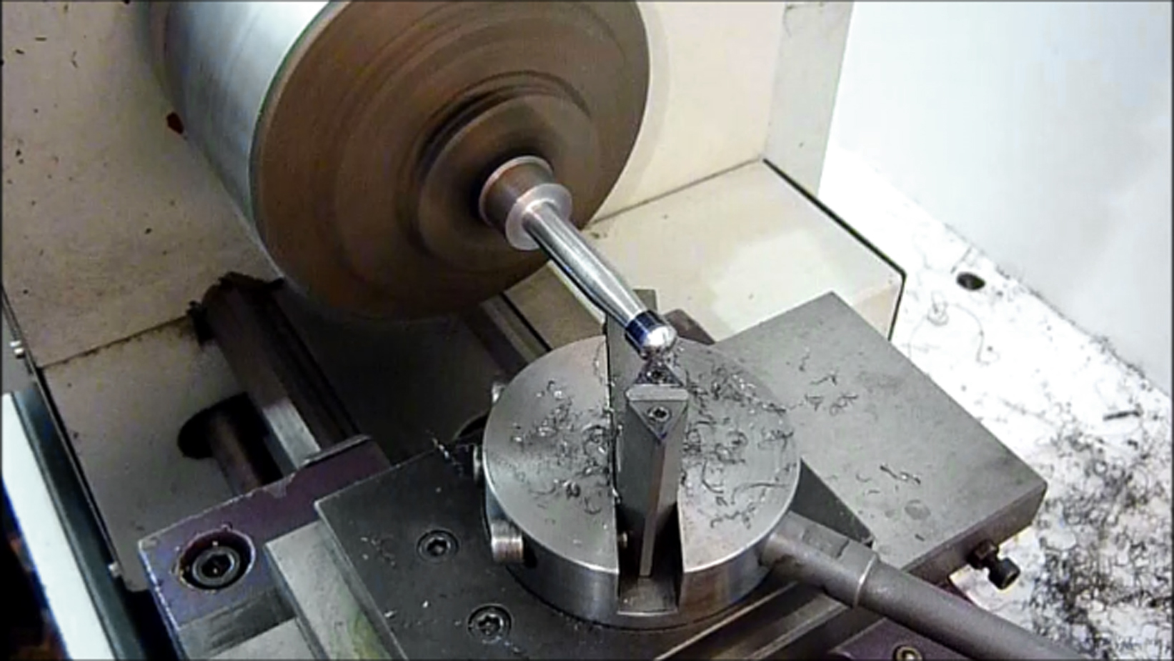
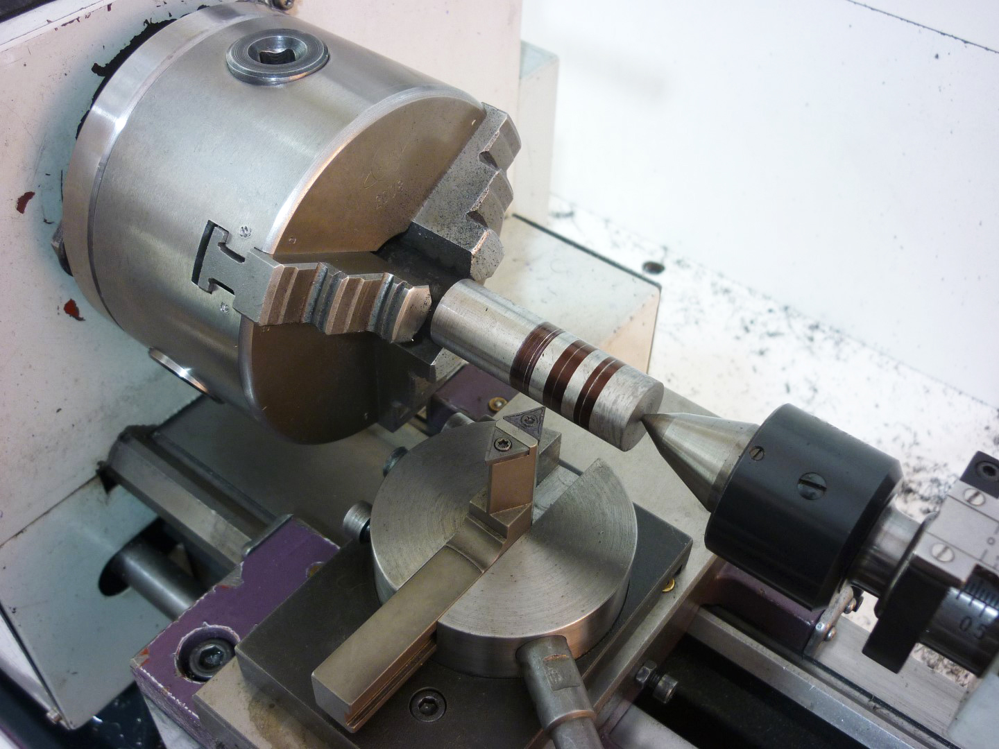
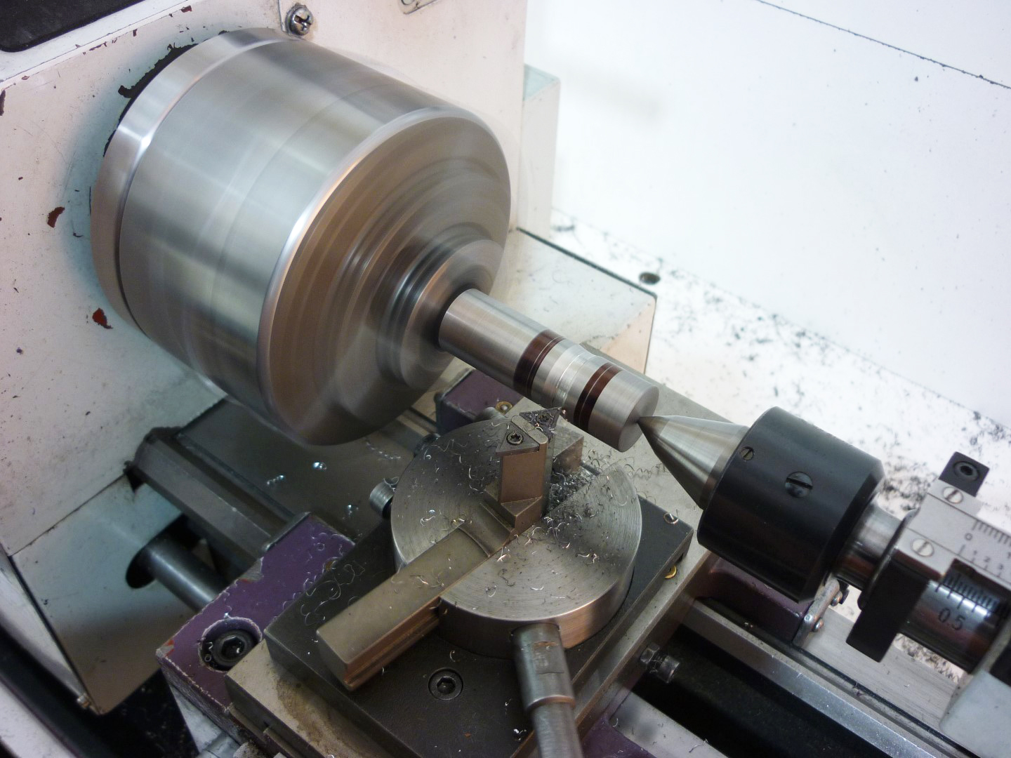
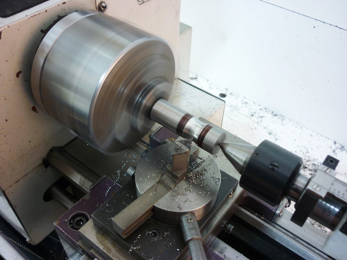
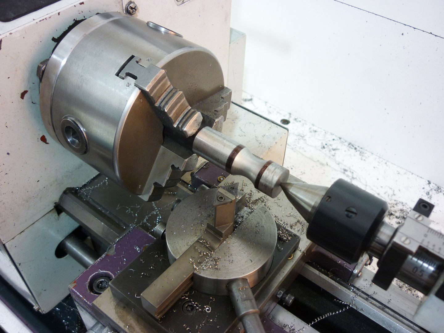
Here are some pictures with the tool as it used
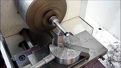
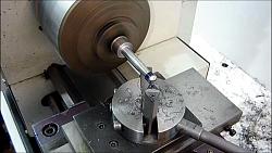
Unfortunately I don't have a video on building the tool, but I do have one while Im using it to make a tool similar to a Snarling iron. I hope that you will find it interesting.
All the best
Dimitris


 Reply With Quote

Bookmarks